
Subscribe to Our Youtube Channel
Related Manuals for PIETRO FIORENTINI VSAM 65 BP


Summary of Contents for PIETRO FIORENTINI VSAM 65 BP
- Page 1 VS/AM 65 Relief valve Revision A - Edition 05/2023 USE, MAINTENANCE AND WARNING MANUAL...
- Page 2 RELIEF VALVE INTRODUCTION REV. A Technical manual...
-
Page 3: Introduction
Training the personnel in charge is essential in order to: • the use and maintenance of the device in the correct manner; • correctly apply the safety alerts and recommended procedures. Revision: A COPYRIGHT 2023 © PIETRO FIORENTINI S.P.A. RELIEF VALVE INTRODUCTION REV. A Technical manual... - Page 4 RELIEF VALVE INTRODUCTION REV. A Technical manual...
-
Page 5: Revision History
1.1 - REVISION HISTORY Revision Date Revision contents index 05/2023 First issue Tab. 1.1. RELIEF VALVE INTRODUCTION REV. A Technical manual... -
Page 6: Table Of Contents
INDEX 1 - INTRODUCTION ........................3 1.1 - REVISION HISTORY ..........................5 2 - GENERAL INFORMATION ....................9 2.1 - MANUFACTURER IDENTIFICATION ......................9 2.2 - IDENTIFICATION OF THE PRODUCT ......................9 2.3 - REGULATORY FRAMEWORK ........................9 2.4 - WARRANTY ............................10 2.5 - ADDRESSEES, SUPPLY AND STORAGE OF THE MANUAL .............. - Page 7 5 - TRANSPORT AND HANDLING ..................31 5.1 - SPECIFIC WARNINGS FOR TRANSPORT AND HANDLING ..............31 5.1.1 - PACKAGING AND FASTENERS USED FOR TRANSPORT ..............32 5.2 - PACKAGING CONTENT .......................... 32 5.3 - PHYSICAL CHARACTERISTICS OF THE DEVICE ................... 32 5.4 - DEVICE ANCHORING AND LIFTING METHOD ..................
- Page 8 9 - MAINTENANCE AND FUNCTIONAL CHECKS ..............53 9.1 - GENERAL WARNINGS ........................... 53 9.2 - PERIODICALLY CHECKING AND INSPECTING THE EQUIPMENT FOR PROPER OPERATION ....55 9.2.1 - LEAK TESTING .............................55 9.3 - ROUTINE MAINTENANCE ........................56 9.3.1 - GENERAL SAFETY WARNINGS ......................56 9.3.2 - REPLACEMENT FREQUENCY FOR COMPONENTS SUBJECT TO WEAR ...........56 9.4 - ROUTINE MAINTENANCE PROCEDURES ....................
-
Page 9: General Information
REGULATORY FRAMEWORK PIETRO FIORENTINI S.P.A. with registered office in Arcugnano (Italy) - Via E. Fermi, 8/10, declares under its sole respon- sibility that the VS/AM 65 relief valve covered by this manual, is classified as a safety accessory and is: •... -
Page 10: Warranty
PIETRO FIORENTINI S.P.A. guarantees that the device was manufactured using the best materials, with high quality work- manship, and complies with the quality requirements, specifications and performance set out in the order. The warranty shall be considered null and void and PIETRO FIORENTINI S.P.A. shall not be liable for any damage and/or malfunctions: •... -
Page 11: Symbols Used In The Manual
2.7 - SYMBOLS USED IN THE MANUAL Symbol Definition Symbol used to identify important warnings for the safety of the operator and/or device. Symbol used to identify information of particular importance in the instruction manual. The information may also concern the safety of the personnel involved in using the device. Obligation to consult the instruction manual. -
Page 12: Applied Rating Plates
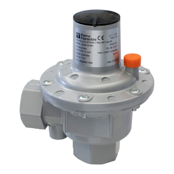
The nameplate (A) contains the identification details of the device and its accessories to be mentioned in case of need at PIETRO FIORENTINI S.p.A.: Type Image VALVOLA DI SFIORO / RELIEF VALVE Model: VSAM 65 BP Fluid: N.G. PS: 20.00 Bar TS: -20/+60 °C IDENTIFICATION PLATE Wd: 0.015÷0.149... -
Page 13: Glossary For Rating Plates
2.8.1 - GLOSSARY FOR RATING PLATES The terms and abbreviations used on the rating plate are described in Tab. 2.6.: Term Description CE marking ensuring the conformity of the product with the requirements of the applicable EU directives or regulations. Identifier of the body that issued the CE marking. -
Page 14: Glossary Of Measurement Units
2.9 - GLOSSARY OF MEASUREMENT UNITS Type of measurement Unit of measurement Description Sm³/h Standard cubic metres per hour Sm³ Standard cubic metres Volumetric flow rate m³/h Cubic metres per hour m³ Cubic metres Unit of measurement in the CGS system Pressure “wc Water column inch... -
Page 15: Qualified Professional Figures
2.10 - QUALIFIED PROFESSIONAL FIGURES Qualified operators in charge of using and managing the device throughout its technical service life: Professional figure Definition Qualified operator able to: • handle materials and equipment; • carry out all the operations necessary to properly install the device; Installer •... - Page 16 PAGE INTENTIONALLY LEFT BLANK RELIEF VALVE GENERAL INFORMATION REV. A Technical manual...
-
Page 17: Safety
3 - SAFETY 3.1 - GENERAL SAFETY WARNINGS WARNING! The device described in this manual is: • subject to pressure in pressurised systems; • normally installed in systems carrying flammable gases (for example: natural gas). WARNING! If the gas used is a combustible gas, the installation area of the device is defined as a “danger zone” as there are residual risks that potentially explosive atmospheres may be generated. -
Page 18: Personal Protective Equipment
3.2 - PERSONAL PROTECTIVE EQUIPMENT The following table shows the Personal Protective Equipment (PPE) and its description; an obligation is associated with each symbol. Personal protective equipment means any equipment intended to be worn by the worker in order to protect them against one or several risks that are likely to threaten their safety or health during work. -
Page 19: Obligations And Prohibitions
WARNING! If there are any functional faults, do not operate. Immediately contact PIETRO FIORENTINI S.p.A. for the necessary directions. In accordance with the requirements of PED Directive 2014/68/EU point 1.2 of Annex I, below is an assessment of the risks associated with the device and an indication of the principles adopted for their prevention, according to the following classification: a) Elimination and/or reduction of the risk. - Page 20 3.4.1 - TABLE SHOWING RESIDUAL RISKS DUE TO PRESSURE WARNING! If there are any functional faults, do not operate. Immediately contact PIETRO FIORENTINI S.p.A. for the necessary directions. Effect and Risk and Hazard Event and Cause Solution and Prevention Consequence Pressurised gas •...
- Page 21 • deterioration of Projection of • environments with a. The user must shut off the line and con- external surfaces; metallic and aggressive atmos- tact PIETRO FIORENTINI S.p.A. • corrosion. non-pressurised phere. parts. Tab. 3.10. RELIEF VALVE SAFETY REV. A...
-
Page 22: Table Of Residual Risks For Potentially Explosive Atmospheres
3.4.2 - TABLE OF RESIDUAL RISKS FOR POTENTIALLY EXPLOSIVE ATMOSPHERES Table 3.11 shows the conditions that can lead to the generation of a potentially explosive atmosphere respectively for: • the pressure regulator; • the monitor; • the slam-shut device. The table is valid for use with natural gas with a density of no more than 0.8; for different densities, the installation and environmental conditions must also be evaluated. - Page 23 Potentially Management measures in- Operating explosive Normative references cluded in the instructions for conditions atmosphere use and warning This type of malfunction is not rea- Breakage of other sonably expected as it involves stat- non-metallic parts ic seals (to the outside) that cannot (malfunction) generate any external leakage.
-
Page 24: Safety Pictograms
NOISE LEVEL VS/AM 65 is a safety device that does not entail the flow of gas inside under normal system operating conditions. For the value of the noise generated by the device and further information, contact PIETRO FIORENTINI S.p.A. ATTENTION! The obligation to use earmuffs or ear plugs to protect the hearing of qualified professional figures (ref- erence paragraph 2.10) remains in the event that the noise in the installation environment of the device... -
Page 25: Description And Operation
4 - DESCRIPTION AND OPERATION 4.1 - GENERAL DESCRIPTION The relief valves in the VS/AM 65 series are safety devices suitable for: • pre-purified gaseous fluids; • medium and low pressure systems. The main elements of the device are: Pos. Description Pos. -
Page 26: Operation
4.2 - OPERATION NOTICE! Activation of the VS/AM 65 relief valve involves no external control sources other than the fluid itself. The relief valves in the VS/AM 65 series are safety devices that: • may be installed either on ducts or on pressure vessels; •... -
Page 27: Intended Use
If no written approval is provided, use shall be considered improper. In the event of “improper use”, PIETRO FIORENTINI S.p.A. shall not be held liable for any damage caused to people or property, and any type of warranty on the device shall be deemed void. -
Page 28: Models And Configurations
4.4 - MODELS AND CONFIGURATIONS The device models differ according to the adjustment range as shown in Tab. 4.15.: Model name Adjustment range 15 - 150 mbar 150 - 500 mbar 500 - 7000 mbar Tab. 4.15. Other configurations can be set up according to inlet/outlet connections, as shown in Tab. 4.16.: Type Image STANDARD... -
Page 29: Technical Features/Performance
4.5 - TECHNICAL FEATURES/PERFORMANCE The main technical features of the device are listed in Tab. 4.17: Technical features Design pressure 20 bar Version BP: 15 - 150 mbar Calibration adjustment range MP version: 150 - 500 mbar TR Version: 500 - 7000 mbar Accuracy class up to 2.5 (depending on output pressure range) Minimum: - 20°C... - Page 30 PAGE INTENTIONALLY LEFT BLANK RELIEF VALVE DESCRIPTION AND OPERATION REV. A Technical manual...
-
Page 31: Transport And Handling
5 - TRANSPORT AND HANDLING 5.1 - SPECIFIC WARNINGS FOR TRANSPORT AND HANDLING NOTICE! Transport and handling must be carried out in compliance with the regulations in force in the country of installation by personnel who are: • qualified (specially trained); •... -
Page 32: Packaging And Fasteners Used For Transport
PIETRO FIORENTINI S.p.A.. NOTICE! PIETRO FIORENTINI S.p.A. shall not be liable for any damage to people or property caused by accidents due to failure to comply with the instructions provided in this manual. Tab. 5.19. describes the types of packaging used: Ref. - Page 33 Tab. 5.21. Weights [kg] Without packaging 0,9 kg Including packaging 1 kg Tab. 5.22. NOTICE! Please refer to the product configurator ("sizing") at PIETRO FIORENTINI S.p.A. for equipment dimensions and weights. RELIEF VALVE TRANSPORT AND HANDLING REV. A Technical manual...
-
Page 34: Device Anchoring And Lifting Method
5.4 - DEVICE ANCHORING AND LIFTING METHOD HAZARD! Using lifting equipment (if necessary) for unloading, carrying and handling packages is reserved only for skilled operators who have been properly trained (and are appropriately qualified if required by the regula- tions in force in the country of installation) and are familiar with: •... -
Page 35: Forklift Handling Method
5.4.1 - FORKLIFT HANDLING METHOD HAZARD! It is forbidden to: • Do not transit under suspended loads; • Do not move the load over the personnel operating in the site/plant area. WARNING! The following is not allowed on forklifts: • carrying passengers;... - Page 36 Step Action Image Sollevare lentamente il carico di qualche decina di centimetri e veri carne la stabilità facendo attenzio- Inclinare il montante all’indietro (verso il posto guida) per avvantaggiare il momento ribaltante e Adeguare la velocità d ne che il baricentro del carico sia posizionato al centro delle forche di sollevamento. garantire una maggiore stabilità...
-
Page 37: Packaging Removal
• do not install the equipment; • contact PIETRO FIORENTINI S.p.A. and specify the details provided on the device nameplate. WARNING! The individual device is contained in a specially designed cardboard box. Avoid taking the device out of the box before its installation. -
Page 38: Storage And Environmental Conditions
5.6 - STORAGE AND ENVIRONMENTAL CONDITIONS WARNING! Protect the regulator from blows and impacts, even accidental, until it is installed. The following table shows the minimum environmental conditions to be expected should the device be stored for an ex- tended period. Compliance with these conditions will guarantee the declared performance: Conditions Data... -
Page 39: Installation
6 - INSTALLATION 6.1 - INSTALLATION PRE-REQUISITES 6.1.1 - ALLOWED ENVIRONMENTAL CONDITIONS WARNING! To safely use the device, in full respect of the allowed environmental conditions, follow the data shown on the regulator plate and on any accessories (refer to paragraph 2.8 “Nameplates applied”). WARNING! The device must be installed away from atmospheric agents and direct sunlight. -
Page 40: Checks Before Installation
6.1.3 - CHECKS BEFORE INSTALLATION The device does not require any further upstream safety device for protection against any overpressure with respect to its PS admissible pressure when, for the upstream reduction station, the maximum incidental downstream pressure MIPd ≤ 1.1 PS MIPd = Maximum incidental downstream pressure value (for further information, see UNI EN 12186:2014). -
Page 41: Specific Safety Instructions For The Installation Step
It is the responsibility of the system designer to correctly dimension the discharge line downstream of the device in accordance with the design conditions. WARNING! The installer must use fittings and gaskets recommended by PIETRO FIORENTINI S.p.A. WARNING! In order to avoid breakage or unwanted deformation, it is necessary to: •... -
Page 42: Possible Installations Of The Device
6.3 - POSSIBLE INSTALLATIONS OF THE DEVICE NOTICE! • With natural gas or other non-corrosive gases that are not subject to recondensation, the device can be installed in any flow direction. • Please avoid any mounting positions with outlet flow facing upwards in installations using LPG. For information about how to mount the device in keeping with the available models and configurations, refer to Tab. -
Page 43: Installation Procedure
6.4 - INSTALLATION PROCEDURE Installation Operator qualification • Installer. WARNING! The PPE listed in this table is related to the risk associated with the device. For PPE required the PPE required to protect against risks associated with the workplace, instal- lation or operating conditions, please refer to: •... -
Page 44: Device Installation Procedure
Valvola intercettatrice Fig. 6.5. Installation scheme NOTICE! The warranty shall be deemed null and void and PIETRO FIORENTINI S.p.A. shall not be held liable for any damage and/or malfunctions if the fittings used during installation are not those supplied. 6.5 - POST-INSTALLATION CHECKS To perform the post-installation check, proceed as shown in Tab. -
Page 45: Commissioning/Maintenance Equipment
7 - COMMISSIONING/MAINTENANCE EQUIPMENT 7.1 - LIST OF EQUIPMENT Use of commissioning/maintenance equipment • Name of the user. Operator qualification • Specialised technician. WARNING! The PPE listed in this table is related to the risk associated with the device. For PPE required the PPE required to protect against risks associated with the workplace, instal- lation or operating conditions, please refer to:... - Page 46 PAGE INTENTIONALLY LEFT BLANK RELIEF VALVE REV. A COMMISSIONING AND MAINTENANCE EQUIPMENT Technical manual...
-
Page 47: Commissioning
8 - COMMISSIONING 8.1 - GENERAL WARNINGS 8.1.1 - SAFETY REQUIREMENTS FOR COMMISSIONING HAZARD! During commissioning the risks associated with any discharges to the atmosphere of flammable or nox- ious gases must be evaluated. HAZARD! In case of installation on distribution networks for natural gas, consider the risk associated with explosive mixtures (gas/air) being formed inside the piping, if the line is not subjected to inerting. -
Page 48: Preliminary Procedures For Commissioning
ATTENTION! Observe the spring calibration ranges given in the tables in Chapter 10 ('Calibration tables'). NOTICE! The device is regulated at the PIETRO FIORENTINI S.p.A. production facilities Check calibrations according to the procedures outlined in the following paragraphs. RELIEF VALVE COMMISSIONING REV. -
Page 49: Device Commissioning Procedure
8.4 - DEVICE COMMISSIONING PROCEDURE Commissioning Operator qualification • User/specialist technician. WARNING! The PPE listed in this table is related to the risk associated with the device. For PPE required the PPE required to protect against risks associated with the workplace, instal- lation or operating conditions, please refer to: •... -
Page 50: Commissioning Without Shut-Off Valve
8.4.1 - COMMISSIONING WITHOUT SHUT-OFF VALVE When the device is installed directly on the line, i.e. without the interposition of a shut-off valve, proceed as shown in Tab. 8.34: Step Action Ensure that the outlet shut-off valve (V2) and the air vent valve (6) are closed. Connect a controlled auxiliary pressure to the cock (6) and stabilise it at the desired cut-in value. -
Page 51: Device Settings
8.5 - DEVICE SETTINGS NOTICE! All devices are calibrated to the values requested by the customer directly at PIETRO FIORENTINI S.p.A. factory The calibration values are specified on the nameplate (refer to paragraph 2.8 “Applied rating plates”). It is forbidden to make unauthorised changes to the device. - Page 52 If it is necessary to adjust the tripping pressure of the relief valve, proceed as shown in Tab.8.37: Step Action Necessary equipment Unscrew the top cap (A). Turn the ring nut (B): • clockwise to increase tripping pressure; 27 mm tubular socket wrench •...
-
Page 53: Maintenance And Functional Checks
5 m/sec. WARNING! In case of doubt, do not perform any work. Contact PIETRO FIORENTINI S.p.A. for the necessary clarifica- tions. The management and/or use of the device includes interventions that are necessary as a result of normal use such as: •... - Page 54 Before beginning disassembly of the device, make sure that: • the spare parts and parts used in replacements have adequate requirements to ensure the original performance of the device. Use recommended original spare parts; • the operator has the necessary equipment (see chapter 7 “Equipment for commissioning/maintenance”). NOTICE! The recommended spare parts are unambiguously identified with tags indicating: •...
-
Page 55: Periodically Checking And Inspecting The Equipment For Proper Operation
9.2 - PERIODICALLY CHECKING AND INSPECTING THE EQUIPMENT FOR PROPER OPERATION HAZARD! Checks and inspections are only carried out by authorised technicians after notification to the manufac- turer. Periodic checks and inspections Operator qualification • User/specialist technician. WARNING! The PPE listed in this table is related to the risk associated with the device. For PPE required the PPE required to protect against risks associated with the workplace, instal- lation or operating conditions, please refer to:... -
Page 56: Routine Maintenance
9.3 - ROUTINE MAINTENANCE 9.3.1 - GENERAL SAFETY WARNINGS HAZARD! • Put the device in a safe condition (close the downstream and then the upstream shut-off valve, drain the device completely and lastly drain the line); • Ensure that the pressure upstream and downstream of the device is “0”. NOTICE! Before installing new sealing elements (o-rings, diaphragm, etc.), they must be checked for integrity. - Page 57 Minimum Category Part description Evaluation criterion replacement frequency Non-metallic parts with sealing function involved in disassembly operations during Equipment subject to maintenance 6 years maintenance. Non-metallic parts providing feedback (sensing elements) of the controlled pres- Safety equipment and/or accessories 6 years sure of safety equipment.
-
Page 58: Routine Maintenance Procedures
9.4 - ROUTINE MAINTENANCE PROCEDURES Routine maintenance Operator qualification • User/specialist technician. WARNING! The PPE listed in this table is related to the risk associated with the device. For PPE required the PPE required to protect against risks associated with the workplace, instal- lation or operating conditions, please refer to: •... - Page 59 PAGE INTENTIONALLY LEFT BLANK RELIEF VALVE MAINTENANCE AND FUNCTIONAL CHECKS REV. A Technical manual...
- Page 60 TESTATA TR RELIEF VALVE MAINTENANCE AND FUNCTIONAL CHECKS REV. A Technical manual...
- Page 61 NOTICE! The maintenance procedure described in Tab. 9.45 is valid for all models listed in section 2.2 (Tab. 2.3.). Any differences between models are explained in the specific step of the maintenance procedure. To service the internal components of the relief valve, proceed as shown in Tab. 9.45.: Step Action Unscrew and remove the cap (A).
- Page 62 TESTATA TR RELIEF VALVE MAINTENANCE AND FUNCTIONAL CHECKS REV. A Technical manual...
- Page 63 Step Action Remove the 'U' ring (U) from the plug (M). Lubricate the 'U' ring (U) and reinsert it into the plug (M). Assemble the plug guide assembly (K). Insert and secure the nut (L). Equipment required: spanner CH 8. NOTICE! During this step, hold the plug (M) still.
- Page 64 PAGE INTENTIONALLY LEFT BLANK RELIEF VALVE MAINTENANCE AND FUNCTIONAL CHECKS REV. A Technical manual...
-
Page 65: Troubleshooting
• qualified and authorised to carry out activities related to the device. WARNING! PIETRO FIORENTINI S.p.A. shall not be held liable for any damage to people and property due to services: • other than those described; • performed according to methods other than those specified;... -
Page 66: Operator Qualification Specification
10.2 - OPERATOR QUALIFICATION SPECIFICATION Troubleshooting Operator qualification • User/specialist technician. WARNING! The PPE listed in this table is related to the risk associated with the device. For PPE required the PPE required to protect against risks associated with the workplace, instal- lation or operating conditions, please refer to: •... -
Page 67: Uninstallation And Disposal
11 - UNINSTALLATION AND DISPOSAL 11.1 - GENERAL SAFETY WARNINGS HAZARD! Make sure that there are no potentially explosive ignition sources in the work area set up to uninstall and/ or dispose of the device. WARNING! Before proceeding with uninstallation and disposal, make the device safe by disconnecting it from any power supply. -
Page 68: Information Required In Case Of Re-Installation
11.4 - INFORMATION REQUIRED IN CASE OF RE-INSTALLATION NOTICE! Should the device be reused after uninstallation, refer to chapters: • “Installation”; • “Commissioning”. 11.5 - DISPOSAL INFORMATION NOTICE! • Proper disposal prevents damage to humans and the environment and promotes the reuse of precious raw materials. -
Page 69: Recommended Spare Parts
If spare parts not marked are used, PIETRO FIORENTINI S.p.A. their declared performance cannot be guaranteed. It is recommended to use original spare parts PIETRO FIORENTINI S.p.A. PIETRO FIORENTINI S.p.A. shall not be held liable for any damage caused by using non-original parts. 12.2 - HOW TO REQUEST SPARE PARTS NOTICE! For specific information, please refer to the sales network of PIETRO FIORENTINI S.p.A. - Page 70 PAGE INTENTIONALLY LEFT BLANK RELIEF VALVE RECOMMENDED SPARE PARTS REV. A Technical manual...
-
Page 71: Calibration Tables
13 - CALIBRATION TABLES 13.1 - CALIBRATION TABLES NOTICE! When the value indicated on the rating plate of the device is equal to the minimum or maximum value of a spring mentioned in the tables, the spring in the device is the one with the minimum range value equal to the calibration value on the rating plate. - Page 72 TM0050ENG...
Need help?
Do you have a question about the VSAM 65 BP and is the answer not in the manual?
Questions and answers