Table of Contents
Advertisement
Available languages
Available languages
Quick Links
INSTALLER: LEAVE THIS MANUAL WITH THE APPLIANCE.
CONSUMER: RETAIN THIS MANUAL FOR FUTURE REFERENCE.
NEVER LEAVE CHILDREN OR OTHER AT RISK INDIVIDUALS ALONE WITH THE APPLIANCE.
CONFORMS TO AMERICAN NATIONAL STANDARDS: ANSI Z21.50, CERTIFIED TO CANADIAN CSA 2.22 FOR VENTED GAS FIREPLACES.
CERTIFIED FOR CANADA AND UNITED STATES USING ANSI/CSA METHODS.
SAFETY INFORMATION
WARNING
!
If the information in these instructions are
not followed exactly, a fi re or explosion
may result causing property damage,
personal injury or loss of life.
- Do not store or use gasoline or other fl ammable
vapors and liquids in the vicinity of this or any
other appliance.
- WHAT TO DO IF YOU SMELL GAS:
•
Do not try to light any appliance.
•
Do not touch any electrical switch; do not use
any phone in your building.
•
Immediately call your gas supplier from a
neighbour's phone. Follow the gas supplier's
instructions.
•
If you cannot reach your gas supplier, call the
fi re department.
- Installation and service must be performed by a
qualifi ed installer, service agency or the supplier.
This appliance is only for use with the type of gas
indicated on the rating plate. This appliance is
not convertible for use with other gases, unless a
certifi ed kit is used.
Decorative Product: Not for use as a heating appliance.
Phone (705)721-1212 • Fax (705)722-6031 • www.napoleonfi replaces.com • hearth@napoleonproducts.com
$10.00
OPERATING INSTRUCTIONS
Wolf Steel Ltd., 24 Napoleon Rd., Barrie, ON, L4M 0G8 Canada /
103 Miller Drive, Crittenden, Kentucky, USA, 41030
INSTALLATION AND
CBI3600-N
NATURAL GAS
CBI3600-P
DANGER
!
A barrier designed to reduce the risk of burns from
the hot viewing glass is provided with this appliance
and shall be installed for the protection of children
and other at-risk individuals.
PROPANE
HOT GLASS WILL CAUSE
BURNS.
DO NOT TOUCH GLASS UNTIL
COOLED.
NEVER ALLOW CHILDREN TO
TOUCH GLASS.
1.39B
W415-1362 / A / 09.15.16
EN
FR
PG
29
Advertisement
Chapters
Table of Contents

Related Manuals for Napoleon CBI3600-N


Summary of Contents for Napoleon CBI3600-N
- Page 1 Wolf Steel Ltd., 24 Napoleon Rd., Barrie, ON, L4M 0G8 Canada / 103 Miller Drive, Crittenden, Kentucky, USA, 41030 Phone (705)721-1212 • Fax (705)722-6031 • www.napoleonfi replaces.com • hearth@napoleonproducts.com $10.00...
-
Page 2: Table Of Contents
TABLE OF CONTENTS INSTALLATION OVERVIEW INTRODUCTION DIMENSIONS MINIMUM CLEARANCE TO COMBUSTIBLES GENERAL INSTRUCTIONS GENERAL INFORMATION RATING PLATE INFORMATION INSTALLATION LEVELLING THE APPLIANCE CHIMNEY CONNECTION OPTIONAL WALL SWITCH GAS INSTALLATION FINISHING SAFETY SCREEN REMOVAL AND INSTALLATION FIBRE FIREBRICK PANELS DOOR REMOVAL AND INSTALLATION LOG PLACEMENT CHARCOAL EMBERS FLASHING KIT... -
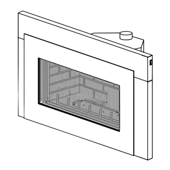
Page 3: Installation Overview
1.0 INSTALLATION OVERVIEW Door, see “SAFETY SCREEN REMOVAL / INSTALLATION” & “DOOR REMOVAL / INSTALLATION” section. Log placement see “LOG PLACEMENT” section. Flashing, see “FLASHING KIT” section. Rating Plate, see “RATING PLATE INFORMATION” section. Blower, see “BLOWER REPLACEMENT” section. W415-1362 / A / 09.15.16... -
Page 4: Introduction
2.0 INTRODUCTION WARNING • THIS APPLIANCE IS HOT WHEN OPERATED AND CAN CAUSE SEVERE BURNS IF CONTACTED. • ANY CHANGES OR ALTERATIONS TO THIS APPLIANCE OR IT’S CONTROLS CAN BE DANGEROUS AND IS PROHIBITED. • Do not operate appliance before reading and understanding operating instructions. Failure to operate appliance according to operating instructions could cause fi... -
Page 5: Dimensions
DIMENSIONS EXHAUST 7" [178mm] 3" [76mm] DIA. 18 1/2" [470mm] 30 1/2" [775mm] 22" ELECTRICAL 17 1/2" [559mm] 8" 2 1/2" INLET LEFT SAFETY BARRIER [445mm] 27 1/2" 17 1/4" [203mm] 13 1/2" [64mm] SIDE [699mm] [438mm] [343mm] 43" [1092mm] 6" (152mm) FLASHING GAS INLET 25"... -
Page 6: General Information
• The fl exible connector must not be longer than 36 inches (914mm). • A Carbon Monoxide detector is required in all rooms containing gas fi red appliances. • The appliance is not approved for installation in a bedroom or bathroom unless the unit is a direct vent sealed combustion product. -
Page 7: Rating Plate Information
ELECTRICAL RATING: 115V, 0.82 AMPS, 60 HZ CLASS: 115V, 0.82 AMPS, 60 HZ OPTIONAL FAN KIT: GZ550-KT EMSEMBLE DE VENTILATION FACULTATIF: GZ550-KT WOLF STEEL LTD. 24 NAPOLEON ROAD, BARRIE, ON, L4M 0G8 CANADA CANADA GI3600 SERIAL NUMBER / NO. DESERIE W385-1982 INSTALLER: It is your responsibility to check off the appropriate box on the rating plate according to the model, venting and gas type of the appliance. -
Page 8: Installation
3.0 INSTALLATION WARNING RISK OF FIRE, MAINTAIN SPECIFIED AIR SPACE CLEARANCES TO VENT PIPE AND APPLIANCE. Clean out ashes from the inside of the wood-burning appliance. Make sure that the chimney and wood-burning appliance are in a clean and sound condition and constructed of non-combustible materials. If necessary have any repair work done by a qualifi... -
Page 9: Optional Wall Switch
OPTIONAL WALL SWITCH WARNING DO NOT CONNECT THE WALL SWITCH OR GAS VALVE DIRECTLY TO 110 VOLT ELECTRICITY. For ease of accessibility, an optional remote wall switch may be installed in a convenient location. Route a 2 strand, solid core millivolt wire from the valve to the wall switch. The recommended maximum lead length depends on wire size: WIRE SIZE MAX. -
Page 10: Finishing
4.0 FINISHING WARNING RISK OF FIRE! NEVER OBSTRUCT THE FRONT OPENING OF THE APPLIANCE. DO NOT STRIKE, SLAM OR SCRATCH GLASS. DO NOT OPERATE APPLIANCE WITH GLASS REMOVED, CRACKED, BROKEN OR SCRATCHED. SAFETY SCREEN REMOVAL AND INSTALLATION WARNING GLASS MAY BE HOT, DO NOT TOUCH GLASS UNTIL COOLED. IF EQUIPPED WITH DOOR LATCHES THAT ARE PART OF A SAFETY RELIEF SYSTEM, THEY MUST BE PROPERLY ENGAGED. -
Page 11: Fibre Firebrick Panels
FIBRE FIREBRICK PANELS To give your insert that authentic masonry look, optional fi bre fi rebrick panels are available at your NAPOLEON / Wolf Steel Ltd. dealer. Complete installation and maintenance instructions are included with the kit. -
Page 12: Log Placement
THE LOGS ARE FRAGILE AND SHOULD BE HANDLED WITH CARE. 76.1A PHAZER logs and glowing embers exclusive to Napoleon appliances, provide a unique and realistic glowing effect that is different in every installation. Take the time to carefully position the glowing embers for a maximum glowing effect. -
Page 13: Flashing Kit
FLASHING KIT TRIM ON/OFF SWITCH FLASHING SECURING SCREWS LEVELING FLAME SCREW SECURING SCREWS ADJUSTMENT PIEZO KNOB IGNITOR OPTIONAL ON/OFF SWITCH LOCATION VARIABLE SPEED SWITCH GAS KNOB The insert can be equipped with a fl ashing kit to close off most appliance openings. Mount the fl ashing inside the unit's outer shell using 4 securing screws. -
Page 14: Operation
5.0 OPERATION When lit for the fi rst time, the appliance will emit an odor for a few hours. This is a normal temporary condition caused by the “burn-in” of paints and lubricants used in the manufacturing process and will not occur again. After extended periods of non-operation such as following a vacation or a warm weather season, the appliance may emit a slight odor for a few hours. -
Page 15: Adjustments
Test after installing the appliance into a vented non-combustible fi replace in the following manner: 1. Close all doors and windows in the room; start exhaust fans in the home; turn the appliance blower off. 2. Set controls to "high" and light the appliance. 3. -
Page 16: Flame Characteristics
FLAME CHARACTERISTICS It’s important to periodically perform a visual check of the pilot and burner fl ames. Compare them to the illustrations provided. If any fl ame 3/8” - 1/2” appears abnormal call a service person. (9.5mm - 12.7mm) THERMOPILE PILOT BURNER ELECTRODE BLOWER REPLACEMENT... -
Page 17: Maintenance
7.0 MAINTENANCE MAINTENANCE MAINTENANCE WARNING MAINTENANCE TURN OFF THE GAS AND ELECTRICAL POWER BEFORE SERVICING THE APPLIANCE. APPLIANCE MAY BE HOT, DO NOT SERVICE UNTIL APPLIANCE HAS COOLED. DO NOT USE ABRASIVE CLEANERS. DO NOT PAINT THE PILOT ASSEMBLY. This appliance and its venting system should be inspected before use and at least annually by a qualifi ed service person. -
Page 18: Care Of Glass
• Inspect all accessible gaskets and replace as required. • Access the blower, if equipped and clean using a soft brush and vacuum. • Re-assemble the various components in reverse order. • Inspect the relief system. The appliance relieves through the main glass door or through the fl aps on the If equipped, inspect the relief system. -
Page 19: Replacements
8.0 REPLACEMENTS WARNING FAILURE TO POSITION THE PARTS IN ACCORDANCE WITH THIS MANUAL OR FAILURE TO USE ONLY PARTS SPECIFICALLY APPROVED WITH THIS APPLIANCE MAY RESULT IN PROPERTY DAMAGE OR PERSONAL INJURY. Contact your dealer for questions concerning prices and policies on replacement parts. Normally, all parts can be ordered through your Authorized dealer / distributor. -
Page 20: Overview
W415-1362 / A / 09.15.16... -
Page 21: Accerssories
W415-1362 / A / 09.15.16... -
Page 22: Troubleshooting
11.0 TROUBLESHOOTING WARNING ALWAYS LIGHT THE PILOT WHETHER FOR THE FIRST TIME OR IF THE GAS SUPPLY HAS RUN OUT, WITH THE GLASS DOOR OPEN OR REMOVED. TURN OFF THE GAS AND ELECTRICAL POWER BEFORE SERVICING THE APPLIANCE. APPLIANCE MAY BE HOT, DO NOT SERVICE UNTIL APPLIANCE HAS COOLED. DO NOT USE ABRASIVE CLEANERS. - Page 23 SYMPTOM PROBLEM TEST SOLUTION Pilot will not light. No spark at pilot burner. Check if pilot can be lit by a match. Check that the wire is connected to the push button igniter. Check if the push button igniter needs tightening. Replace the wire if the wire insulation is broken or frayed.
-
Page 24: Warranty
All parts replaced under the President’s Limited Lifetime Warranty Policy are subject to a single claim. During the fi rst 10 years NAPOLEON will replace or repair the defective parts covered by the lifetime warranty at our discretion free of charge. -
Page 25: Service History
13.0 SERVICE HISTORY W415-1362 / A / 09.15.16... -
Page 26: Notes
14.0 NOTES 44.1 W415-1362 / A / 09.15.16... - Page 27 44.1 W415-1362 / A / 09.15.16...
- Page 28 napoleonproducts.com...
- Page 29 à risque. ÉCRAN DE PROTECTION Wolf Steel Ltd., 24 Napoleon Rd., Barrie, ON, L4M 0G8 Canada / 103 Miller Drive, Crittenden, Kentucky, USA, 41030 Téléphone 705-721-1212 • Télécopieur 705-722-6031 • www.napoleonfoyers.com • hearth@napoleonproducts.com 10,00 $ 1.39B...
- Page 30 TABLE DES MATIERES SURVOL DE L'INSTALLATION INTRODUCTION DIMENSIONS DÉGAGEMENT MINIMAL AUX ENCEINTES COMBUSTIBLES INSTRUCTIONS GÉNÉRALES INFORMATION GÉNÉRALE EMPLACEMENT DE LA PLQUE D'HOMOLOGATION INSTALLATION MISE À NIVEAU DE L'ENCASTRÉ INSTALLATION DE LA CHEMINÉE INTERRUPTEUR MARCHE/ARRÊT OPTIONELLE BRANCHEMENT DU GAZ FINITIONS OUVERTURE ET FERMETURE DE L'ÉCRAN DE PROTECTION OUVERTURE ET FERMETURE DE LA PORTE INSTALLATION DES PANNEAUX DÉCORATIFS SIMILI-BRIQUES DISPOSITION DES BÛCHES...
-
Page 31: Survol De L'installation
1.0 SURVOL DE L'INSTALLATION Porte, voir la section «OUVERTURE ET FERMETURE DE L'ÉCRAN DE PROTECTION» et «OUVERTURE FERMETURE DE LA PORTE » Bûches, voir la section « DISPOSITION DES BÛCHES ». Contour, voir la section « ENSEMBLE DE CONTOUR ». Plaque d’homologation, voir la section «... -
Page 32: Introduction
2.0 INTRODUCTION AVERTISSEMENT • CET APPAREIL EST CHAUD LORSQU’IL FONCTIONNE ET PEUT CAUSER DE GRAVES BRÛLURES EN CAS DE CONTACT. • TOUTE MODIFICATION APPORTÉE À CET APPAREIL OU AUX CONTRÔLES PEUT ÊTRE DANGEREUX ET EST INTERDIT. • Ne faites pas fonctionner l’appareil avant d’avoir lu et compris les instructions d’opération. Omettre d’utiliser l’appareil selon les instructions d’opération pourrait causer un incendie ou des blessures. -
Page 33: Dimensions
DIMENSIONS 7" [178mm] ÉCHAPPEMENT 3" [76mm] DIA. 18 1/2" [470mm] 30 1/2" [775mm] 22" ENTRÉE 17 1/2" [559mm] 8" ÉCRAN DE ÉLECTRIQUE 2 1/2" [445mm] 27 1/2" 17 1/4" PROTECTION [203mm] 13 1/2" CÔTÉ GAUCHE [64mm] [699mm] [438mm] [343mm] 25" [635mm] 43"... -
Page 34: Information Générale
• Ce produit doit être installé par un plombier certifi é ou un installateur pour le gaz lorsque installé dans le Commonwealth du Massachusetts. • Le registre de l’appareil doit être enlevé ou bloqué en le soudant en position ouverte avant d’installer un encastré ou un ensemble de bûches à... -
Page 35: Emplacement De La Plque D'homologation
ELECTRICAL RATING: 115V, 0.82 AMPS, 60 HZ CLASS: 115V, 0.82 AMPS, 60 HZ OPTIONAL FAN KIT: GZ550-KT EMSEMBLE DE VENTILATION FACULTATIF: GZ550-KT WOLF STEEL LTD. 24 NAPOLEON ROAD, BARRIE, ON, L4M 0G8 CANADA RRIE, ON, L4M 0G8 CANAD GI3600 SERIAL NUMBER / NO. DESERIE W385-1982 INSTALLATEUR: Vous êtes responsable de cocher les cases appropriées sur la plaque d’homologation... -
Page 36: Installation
3.0 INSTALLATION AVERTISSEMENT RISQUE D’INCENDIE CONSERVEZ LES DÉGAGEMENTS NÉCESSAIRES AU CONDUIT D’EVENT ET À L’APPAREIL. Retirez les cendres de l’appareil de chauffage au bois. Assurez-vous que la cheminée et l’appareil de chauffage au bois sont propres et en bon état et qu’ils sont construits avec des matériaux incombustibles. Si nécessaire, faites faire les travaux de réparation par une personne qualifi... -
Page 37: Interrupteur Marche/Arrêt Optionelle
INTERRUPTEUR MARCHE/ARRÊT OPTIONELLE AVERTISSEMENT NE RACCORDEZ PAS L’INTERRUPTEUR MURAL, LE THERMOSTAT OU LA SOUPAPE DE GAZ À L’ALIMENTATION ÉLECTRIQUE DE 110 VOLTS. Pour faciliter l’accès, un interrupteur mural ou un thermostat millivolt optionnel peut être installé à un endroit pratique. Passez un fi l millivolt à deux brins (noyau solide) de la soupape à l’interrupteur mural ou au thermo- stat millivolt. -
Page 38: Finitions
4.0 FINITIONS AVERTISSEMENT RISQUE D’INCENDIE! N’OBSTRUEZ JAMAIS L’OUVERTURE SUR LE DEVANT DE L’APPAREIL. NE FRAPPEZ PAS, NE CLAQUEZ PAS ET N’ÉGRATIGNEZ PAS LA PORTE VITRÉE. NE FAITES PAS Ê É FONCTIONNER L’APPAREIL LORSQUE LA PORTE VITRÉE EST ENLEVÉE, FISSURÉE, BRISÉE OU ÉGRATIGNÉE. -
Page 39: Ouverture Et Fermeture De La Porte
ENLÈVEMENT: AGRAFE Enlevez l'agrafe supérieur. Enlevez l'écran de protection à partir la cadre de l'écran par glissement vers le haut et l'extérieur. Enlevez le deux vis à partir la support du SUPPORT DE SUPÉRIEUR supérieur de l'encadrement de porte. Soulevez la cadre de l'écran de protection à... -
Page 40: Disposition Des Bûches
DISPOSITION DES BÛCHES AVERTISSEMENT OMETTRE DE POSITIONNER LES BÛCHES CONFORMÉMENT AUX SCHÉMAS OU OMETTRE D’UTILISER UNIQUEMENT DES BÛCHES SPÉCIFIQUEMENT APPROUVÉES POUR CET APPAREIL PEUT CAUSER DES DOMMAGES MATÉRIELS OU DES BLESSURES CORPORELLES. LES BÛCHES DOIVENT ÊTRE PLACÉES CORRECTEMENT À L’INTÉRIEUR DE L’APPAREIL. NE CHANGEZ PAS LA POSITION DES BÛCHES CAR L’APPAREIL RISQUE DE NE PAS FONCTIONNER ADÉQUATEMENT ET UN RETARD D’ALLUMAGE RISQUE DE SE PRODUIRE. -
Page 41: Ensemble De Contour
ENSEMBLE DE CONTOUR GARNITURE INTERRUPTEUR MARCHE/ARRÊT CONTOUR VIS D’ATTACHÉ NIVELEUSE ALLUMEUR VIS D’ATTACHÉ BOUTON PIÉZO D’AJUSTEMENT EMPLACEMENT DE LA FLAMME OPTIONNEL INTERRUPTEUR MARCHE/ARRÊT BOUTON INTERRUPTEUR À DE GAZ VITESSE VARIABLE Vous pouvez installer un contour autour de l'encastré afi n de couvrir la plupart des ouvertures de foyer. Fixez le contour au bord intérieur du caisson à... -
Page 42: Fonctionnement
5.0 FONCTIONNEMENT Lorsqu’il est allumé pour la première fois, l’appareil dégagera une légère odeur pendant quelques heures. Cela est une condition normale temporaire causée par le conditionnement des bûches et l’évaporation des peintures et lubrifi ants internes utilisés dans le processus de fabrication; elle ne se reproduira plus. Après de longues périodes sans utiliser l’appareil, comme à... -
Page 43: Réglages
Testez après avoir installé l'appareil dans un foyer ventilé incombustible de la façon suivante : Fermez toutes les portes et les fenêtres de la pièce; faites fonctionner les ventilateurs d'évacuation de la maison; éteignez la souffl erie de l'encastré. Réglez les contrôles à "HIGH" et allumez l'appareil. 3. -
Page 44: Flamme Caractéristique
FLAMME CARACTÉRISTIQUE Il est important d’effectuer périodiquement une inspection 3/8” - 1/2” THERMOPILE visuelle de la fl amme de la veilleuse et du brûleur. (9,5mm - 12,7mm) Comparez-les à ces illustrations. Si des fl ammes paraissent anormales, contactez un technicien de service. LA FLAMME DOIT ENVELOPPER LA BRÛLEUR DE... -
Page 45: Entretien
7.0 ENTRETIEN AVERTISSEMENT COUPEZ L’ALIMENTATION EN GAZ ET L’ALIMENTATION ÉLECTRIQUE AVANT DE PROCÉDER À L’ENTRETIEN DE L’APPAREIL. L’APPAREIL PEUT ÊTRE CHAUD. ATTENDEZ QU’IL SOIT REFROIDI AVANT D’EN FAIRE L’ENTRETIEN. N’UTILISEZ PAS DE PRODUITS ABRASIFS. NE PEINTURE PAS L’ASSEMBLAGE DU VEILLEUSE. Assurez-vous que l’appareil fonctionne adéquatement une fois l’entretien terminé. -
Page 46: Soins De La Vitre
• Enlevez aussi tout dépôt se trouvant sur l’assemblage de la veilleuse et aussi, s’il y a lieu, sur la thermopile, le thermocouple, le capteur de fl amme et l’allumeur. NOTE: Vous devrez nettoyer le capteur de fl amme à l’aide d’une morceau de de laine d’acier ou un tampon récurage (Scotch-Brite™) afi n de retirer toute trace d’oxydation. -
Page 47: Rechanges
8.0 RECHANGES AVERTISSEMENT OMETTRE DE POSITIONNER LES PIÈCES CONFORMÉMENT À CE MANUEL OU D’UTILISER UNIQUEMENT DES PIÈCES SPÉCIFIQUEMENT APPROUVÉES POUR CET APPAREIL PEUT CAUSER DES DOMMAGES MATÉRIELS OU DES BLESSURES CORPORELLES. Contactez votre détaillant pour les questions concernant les prix et la disponibilité des pièces de rechange. -
Page 48: Overview
W415-1362 / A / 09.15.16... -
Page 49: Accessories
W415-1362 / A / 09.15.16... -
Page 50: Dépannage
11.0 DÉPANNAGE MAINTENANCE MAINTENANCE AVERTISSEMENT MAINTENANCE ALLUMEZ TOUJOURS LA VEILLEUSE, QUE CE SOIT POUR LA PREMIÈRE FOIS OU LORSQUE L’APPROVISIONNEMENT EN GAZ EST ÉPUISÉ, AVEC LA PORTE VITRÉE OUVERTE OU RETIRÉE. COUPEZ L’ALIMENTATION EN GAZ ET L’ALIMENTATION ÉLECTRIQUE AVANT DE PROCÉDER À L’ENTRETIEN DE L’APPAREIL. - Page 51 SYMPTÔME PROBLÈME SOLUTIONS La veilleuse ne s’allume Aucune étincelle au brûleur de Vérifi ez si la veilleuse peut être allumée avec une allumette. pas. la veilleuse. Vérifi ez si le fi l est raccordé au bouton-poussoir d’ignition. Vérifi ez si le bouton-poussoir d’ignition doit être resserré. Remplacez le fi...
- Page 52 Une pellicule Le souffre du combustible Nettoyez la vitre avec un nettoyeur recommandé. blanche ou grise se forme. se dépose sur la vitre, les NE PAS NETTOYER LORSQU’ELLE EST CHAUDE. bûches ou les parois de la Si vous ne nettoyez pas les dépôts régulièrement, la vitre chambre de combustion.
-
Page 53: Garantie
12.0 GARANTIE Les produits NAPOLÉON sont fabriqués conformément aux normes strictes du Certifi cat d’Assurance de la Qualité mondialement reconnu ISO 9001 : 2008. Les produits NAPOLÉON sont conçus avec des composants et des matériaux de qualité supérieure, assemblés par des artisans qualifi... -
Page 54: Historique D'entretien
13.0 HISTORIQUE D’ENTRETIEN 43.1 W415-1362 / A / 09.15.16... -
Page 55: Notes
14.0 NOTES 44.1 W415-1362 / A / 09.15.16... - Page 56 napoleonproducts.com...
Need help?
Do you have a question about the CBI3600-N and is the answer not in the manual?
Questions and answers