
Related Manuals for Interlogix GE-DS Series


Summary of Contents for Interlogix GE-DS Series
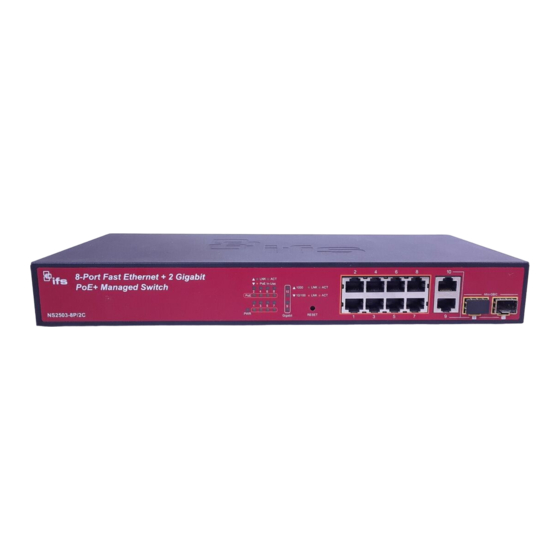
- Page 1 IFS NS2503-8P/2C GE-DS-82 and GE-DS-82-POE User Manual P/N 1072571 • REV 00.06 • ISS 31JAN13...
- Page 2 Copyright © 2013 UTC Fire & Security Americas Corporation, Inc. Interlogix is part of UTC Climate Controls & Security, a unit of United Technologies Corporation. All rights reserved. The IFS NS2503-8P/2C GE-DS-82 and GE-DS-82-POE and logo are Trademarks and patents trademarks of United Technologies.
-
Page 4: Table Of Contents
GE-DS and NS2503 Series User Manual TABLE OF CONTENTS IFS NS2503-8P/2C IFS GE-DS-82 IFS GE-DS-82-POE USER MANUAL....1 INTRODUCTION ......................5 Package Contents ............................5 Product Description...........................6 How to Use This Manual..........................7 Product Features............................8 Product Specification ..........................11 INSTALLATION......................14 Hardware Description ..........................14 Switch Front Panel.......................... -
Page 5: Ifs Ns2503-8P/2C Ifs Ge-Ds-82 Ifs Ge-Ds-82-Poe User Manual
GE-DS-82 and NS2503-8P/2C Series User Manual IP Configuration ..........................37 SNMP Configuration ........................... 39 Firmware Upgrade ..........................46 Configuration Backup ......................... 48 Factory Default ........................... 50 System Reboot ........................... 50 Syslog Setting............................. 51 SMTP Setting............................52 SNTP ..............................53 System Log............................53 Port Configuration .......................... - Page 6 GE-DS-82 and NS2503-8P/2C Series User Manual IGMP Snooping ............................. 102 Theory............................... 102 IGMP Configuration .......................... 106 Static Multicast Table........................108 QoS Configuration ..........................109 Understand QoS ..........................109 QoS Configuration ..........................110 TOS/DSCP ............................113 Access Control List ..........................116 MAC Limit...............................
- Page 7 GE-DS-82 and NS2503-8P/2C Series User Manual Virtual LANs............................152 VLAN Mode: Port-based........................152 Advanced 802.1Q VLAN Configuration .................... 153 Misc Configuration..........................156 Administration Configuration ......................156 Change Username / Password......................156 IP Configuration ..........................157 Reboot switch ........................... 158 Reset to Default ..........................158 TFTP Update Firmware ........................
- Page 8 GE-DS-82 and NS2503-8P/2C Series User Manual Learning ..............................185 Forwarding & Filtering.......................... 185 Store-and-Forward ..........................185 Auto-Negotiation ........................... 186 POWER OVER ETHERNET OVERVIEW..............187 What is PoE? ............................187 The PoE Provision Process ......................... 188 Stages of powering up a PoE link..................... 189 Line Detection...........................
-
Page 9: Introduction
GE-DS-82 and NS2503-8P/2C Series User Manual Introduction The IFS GE-DS-82, GE-DS-82-POE and NS2503-8P/2C switches have 8 10/100Mbps ports with 2 Gigabit TP/SFP fiber optical combo ports and are equipped with robust layer 2 features; the description of these models as below: 8-Port 10/100Base-TX + 2-Port Gigabit TP/SFP Combo Managed Switch GE-DS-82 8-Port 10/100Base-TX + 2-Port Gigabit TP/ SFP Managed PoE Switch... -
Page 10: Product Description
GE-DS-82 and NS2503-8P/2C Series User Manual Product Description High Performance Wire-Speed Switching The IFS GE-DS-82 and NS2503-8P/2C series Managed Switches offers 8 10/100Base-TX Ethernet ports with 2 Gigabit TP / SFP combo ports. These two Gigabit TP/SFP combo ports of these models can be either 1000Base-T for 10/100/1000Mbps or 1000Base-SX/LX through SFP (Small Factor Pluggable) interface. -
Page 11: How To Use This Manual
GE-DS and NS2503 Series User Manual Power over Ethernet of GE-DS-82-POE and NS2503-8P/2C The PoE in-line power following the standards IEEE 802.3af / IEEE 802.3at makes the GE-DS-82-POE and the NS2503-8P/2C able to power on 8 PoE devices at the distance up to 100 meters through the 4-pair Cat 5/5e UTP wire. How to Use This Manual This User Manual is structured as follows: INSTALLATION... -
Page 12: Product Features
GE-DS-82 and NS2503-8P/2C Series User Manual Product Features Physical Port GE-DS-82 8-Port 10/100Base-TX RJ-45 interfaces 2 10/100/1000T TP combo interfaces 2 mini-GBIC/SFP slots, shared with Port-9 and Port-10 Reset button for system management 1 RS-232 male DB9 console interface for Switch basic management and setup GS-DS-82-POE ... - Page 13 GE-DS-82 and NS2503-8P/2C Series User Manual MSTP, IEEE 802.1s (Multiple Spanning Tree Protocol, spanning tree by VLAN) Quality of Service 4 priority queues on all switch ports Traffic classification: IEEE 802.1p Class of Service IP TOS / DSCP code priority ...
- Page 14 GE-DS-82 and NS2503-8P/2C Series User Manual Support PoE Power up to 30 Watts for each PoE ports (NS2503-8P/2C only) Auto detect powered device (PD) Circuit protection prevent power interference between ports Remote power feeding up to 100m ...
-
Page 15: Product Specification
GE-DS-82 and NS2503-8P/2C Series User Manual Product Specification Product GE-DS-82 GE-DS-82-POE NS2503-8P/2C Hardware Specification 8 10/ 100Base-TX RJ-45 8 10/ 100Base-TX RJ-45 8 10/ 100Base-TX RJ-45 10/100Mbps Copper Ports Auto-MDI/MDI-X ports Auto-MDI/MDI-X ports Auto-MDI/MDI-X ports 2 10/100/1000Base-T RJ-45 port 1000Mbps Copper Ports 2 SFP interfaces, shared with Port-9 and Port-10 SFP/mini-GBIC Slots Store-and-Forward... - Page 16 GE-DS-82 and NS2503-8P/2C Series User Manual 802.1p priority, IP DSCP/TOS field in IP Packet v1 and v2 IGMP Snooping 256 multicast groups and IGMP query Per port Ingress / Egress bandwidth control in steps of 128Kbps Bandwidth Control RX / TX / Both Port Mirror 1 to 1 monitor...
- Page 17 GE-DS-82 and NS2503-8P/2C Series User Manual RFC 768 UDP RFC 793 TFTP RFC 791 IP RFC 792 ICMP RFC 2068 HTTP RFC 1112 IGMP version 1 RFC 2236 IGMP version 2 • 50 / 125µm or 62.5 / 125µm multi-mode fiber cable: - 1000Base-SX: up to 220 / 550m Cable-Fiber-optic cable •...
-
Page 18: Installation
GE-DS-82 and NS2503-8P/2C Series User Manual INSTALLATION This section describes the hardware features and installation of the Managed Switch on the desktop or rack mount. For easier management and control of the Managed Switch, familiarize yourself with its display indicators, and ports. Front panel illustrations in this chapter display the unit LED indicators. -
Page 19: Led Indications
GE-DS-82 and NS2503-8P/2C Series User Manual ■ Reset button On the left portion of front panel, the reset button is designed for rebooting the Managed Switch without a power cycle. The following is the summary table of Reset button functions: Reset Button Pressed and Released Function About 1~3 second... - Page 20 GE-DS-82 and NS2503-8P/2C Series User Manual Per 10/100/1000Base-T port /SFP interfaces Color Function Lit: indicate that the port is operating at 1000Mbps. Off: indicate that the port is operating at 10Mbps or 100Mbps. LNK/ACT 1000 Green Blink: indicate that the Switch is actively sending or receiving data over that port. Lit: indicate that the port is operating at 10/100Mbps.
- Page 21 GE-DS-82 and NS2503-8P/2C Series User Manual NS2503-8P/2C LED indication Figure 2-6: NS2503-8P/2C LED panel System Color Function Illuminates to indicate that the Switch has power. Green Per 10/100Base-TX, PoE interfaces (Port-1 to Por-8) Color Function Illuminates: To indicate the link through that port is successfully established. LNK/ACT Green To indicate that the Switch is actively sending or receiving data over that...
-
Page 22: Switch Rear Panel
GE-DS-82 and NS2503-8P/2C Series User Manual Switch Rear Panel The rear panel of the Managed Switch indicates an AC inlet power socket, which works with input power range from 100 to 240V AC, 50-60Hz. Figure 2-7 Figure 2-8 shows the rear panel of the Switch. GE-DS-82 Rear Panel Figure 2-7: GE-DS-82 rear panel. -
Page 23: Install The Switch
GE-DS-82 and NS2503-8P/2C Series User Manual Install the Switch This section describes how to install the Managed Switch and make connections to it. Please read the following topics and perform the procedures in the order being presented. Desktop Installation To install the Managed Switch on desktop or shelf, please follows these steps: Step1: Attach the rubber feet to the recessed areas on the bottom of the Managed Switch. -
Page 24: Rack Mounting
GE-DS-82 and NS2503-8P/2C Series User Manual Rack Mounting To install the Managed Switch in a 19-inch standard rack, please follows the instructions described below. Step1: Place the Managed Switch on a hard flat surface, with the front panel positioned towards the front side. Step2: Attach the rack-mount bracket to each side of the Managed Switch with supplied screws attached to the package. -
Page 25: Installing The Sfp Transceiver
GE-DS-82 and NS2503-8P/2C Series User Manual Installing the SFP Transceiver The sections describe how to plug-in an SFP transceiver into an SFP slot. The SFP transceivers are hot-swappable. You can plug-in and out the transceiver to/from any SFP port without a need to shut down the Managed Switch. - Page 26 GE-DS-82 and NS2503-8P/2C Series User Manual Before connecting to the other switches, workstations or Media Converters do the following: Make sure both sides use the same SFP transceiver, for example: 1000Base-SX to 1000Base-SX, or 1000Bas-LX to 1000Base-LX. make sure that the fiber-optic cable type matches the SFP transceiver model. ...
-
Page 27: Switch Management
GE-DS-82 and NS2503-8P/2C Series User Manual SWITCH MANAGEMENT This chapter explains the methods that you can use to configure management access to the Managed Switch. It describes the types of management applications and the communication and management protocols that deliver data between your management device (work-station or personal computer) and the system. -
Page 28: Management Access Overview
GE-DS-82 and NS2503-8P/2C Series User Manual Management Access Overview The Managed Switch gives you the flexibility to access and manage it using any or all of the following methods: Web browser interface An external SNMP-based network management application ... -
Page 29: Web Management
GE-DS-82 and NS2503-8P/2C Series User Manual Web Management The Managed Switch offers management features that allow users to manage the Managed Switch from anywhere on the network through a standard browser such as Microsoft Internet Explorer. After you set up your IP address for the switch, you can access the Managed Switch’s Web interface applications directly in your Web browser by entering the IP address of the Managed Switch. -
Page 30: Administration Console
GE-DS-82 and NS2503-8P/2C Series User Manual Figure 3-3: SNMP management Administration Console The administration console is an internal, character-oriented, and command line user interface for performing system administration such as displaying statistics or changing option settings. Using this method, you can view the administration console from a terminal, personal computer, Apple Macintosh, or workstation connected to the switch’s console (serial) port. -
Page 31: Protocols
GE-DS-82 and NS2503-8P/2C Series User Manual Figure 3-5: Terminal parameter settings You can change these settings, if desired, after you log on. This management method is often preferred because you can remain connected and monitor the system during system reboots. Also, certain error messages are sent to the serial port, regardless of the interface through which the associated action was initiated. -
Page 32: Snmp Protocol
GE-DS-82 and NS2503-8P/2C Series User Manual SNMP Protocol Simple Network Management Protocol (SNMP) is the standard management protocol for multi-vendor IP networks. SNMP supports transaction-based queries that allow the protocol to format messages and to transmit information between reporting devices and data-collection programs. SNMP runs on top of the User Datagram Protocol (UDP), offering a connectionless-mode service. -
Page 33: Web-Based Management
GE-DS-82 and NS2503-8P/2C Series User Manual Web-Based Management This section introduces the configuration and functions of the Web-Based management. About Web-based Management The Managed Switch offers management features that allow users to manage the Managed Switch from anywhere on the network through a standard browser such as Microsoft Internet Explorer. -
Page 34: Requirements
GE-DS-82 and NS2503-8P/2C Series User Manual Requirements Workstations of subscribers running Windows 98/ME, NT4.0, 2000/2003/XP, MAC OS9 or later, Linux, UNIX or other platform compatible with TCP/IP protocols. Workstation installed with Ethernet NIC (Network Card). Ethernet Port connection ... - Page 35 GE-DS-82 and NS2503-8P/2C Series User Manual Figure 4-1-2: Web main page The Switch Menu on the left of the Web page let you access all the commands and statistics the Switch provides. Now, you can use the Web management interface to continue the switch management or manage the Managed Switch by Web interface.
-
Page 36: Main Web Page
GE-DS-82 and NS2503-8P/2C Series User Manual Main WEB PAGE The Managed Switch provides a Web-based browser interface for configuring and managing it. This interface allows you to access the Managed Switch using the Web browser of your choice. This chapter describes how to use the Managed Switch’s Web browser interface to configure and manage it. -
Page 37: System
GE-DS-82 and NS2503-8P/2C Series User Manual Figure 4-1-4: Managed Switch Main Functions Menu System Use the System menu items to display and configure basic administrative details of the Managed Switch. Under System the following topics are provided to configure and view the system information: This section has the following items: Provides basic system description, including contact information. -
Page 38: System Information
GE-DS-82 and NS2503-8P/2C Series User Manual System Information In System information, it has two parts of setting – Basic and Misc Config. We will describe the configure detail in following. Basic The Basic System Info page provides information for the current device information. Basic System Info page helps a switch administrator to identify the model name, firmware / hardware version and MAC address. - Page 39 GE-DS-82 and NS2503-8P/2C Series User Manual Misc Config Choose Misc Config from System Information of Managed Switch, the screen in Figure 4-2-2 will appear. Figure 4-2-2: Switch Misc Config screenshot The page includes the following fields: Object Description Type the number of seconds that an inactive MAC address remains in the MAC Address Age-out switch’s address table.
- Page 40 GE-DS-82 and NS2503-8P/2C Series User Manual The valid threshold values are 1/2, 1/4, 1/8, 1/16 and OFF. Default is “OFF”. To select broadcast storm Filter Packets type. If no packets type by selected, mean can not filter any packets .The Broadcast Storm Filter Mode will show OFF. The selectable items as below: Broadcast Storm Filter ...
-
Page 41: Ip Configuration
GE-DS-82 and NS2503-8P/2C Series User Manual IP Configuration The Managed Switch is a network device which needs to be assigned an IP address for being identified on the network. Users have to decide on an IP address to the Managed Switch. IP address overview What is an IP address? Each device (such as a computer) which participates in an IP network needs a unique “address”... - Page 42 GE-DS-82 and NS2503-8P/2C Series User Manual If DHCP client function is enabled, this switch is configured as a DHCP client. The network DHCP server will assign the IP address to the switch and display it in this column. The default IP is 192.168.0.100 or the user has to assign an IP address manually when DHCP Client is disabled.
-
Page 43: Snmp Configuration
GE-DS-82 and NS2503-8P/2C Series User Manual SNMP Configuration SNMP Overview The Simple Network Management Protocol (SNMP) is an application layer protocol that facilitates the exchange of management information between network devices. It is part of the Transmission Control Protocol/Internet Protocol (TCP/IP) protocol suite. - Page 44 GE-DS-82 and NS2503-8P/2C Series User Manual SNMP Operations SNMP itself is a simple request/response protocol. NMSs can send multiple requests without receiving a response. Get – Allows the NMS to retrieve an object instance from the agent. Set – Allows the NMS to set values for object instances within an agent. ...
- Page 45 GE-DS-82 and NS2503-8P/2C Series User Manual Figure 4-2-6: Community strings interface The page includes the following fields: Object Description Here you can define the new community string set and remove the unwanted Community Strings: community string. String: Fill the name string. ...
- Page 46 GE-DS-82 and NS2503-8P/2C Series User Manual Trap Managers A trap manager is a management station that receives the trap messages generated by the switch. If no trap manager is defined, no traps will be issued. To define a management station as a trap manager, assign an IP address, enter the SNMP community strings, and select the SNMP trap version.
- Page 47 GE-DS-82 and NS2503-8P/2C Series User Manual Object Description Group Name: A string identifying the group name that this entry should belong to. The allowed string length is 1 to 15. Indicates the security model that this entry should belong to. Possible security V1 | V2c | USM models are: ...
- Page 48 GE-DS-82 and NS2503-8P/2C Series User Manual SNMPv3 Access Configure SNMPv3 accesses table on this page. The entry index keys are Group Name, Security Model and Security Level. The SNMPv3 Accesses Configuration screen is shown in Figure 4-2-10. Figure 4-2-10: SNMP configuration interface The page includes the following fields: Object Description...
- Page 49 GE-DS-82 and NS2503-8P/2C Series User Manual Figure 4-2-11: SNMP configuration interface The page includes the following fields: Object Description A string identifying the user name that this entry should belong to. The allowed SNMP User Name: string length is 1 to 15. Indicates the authentication protocol that this entry should belong to.
-
Page 50: Firmware Upgrade
GE-DS-82 and NS2503-8P/2C Series User Manual Firmware Upgrade It provides the functions allowing the user to update the switch firmware via the Trivial File Transfer Protocol (TFTP) server. Before updating, make sure the TFTP server is ready and the firmware image is located on the TFTP server. TFTP Firmware Upgrade The Firmware Upgrade page provides the functions to allow a user to update the Managed Switch firmware from the TFTP server in the network. - Page 51 GE-DS-82 and NS2503-8P/2C Series User Manual HTTP Firmware Upgrade The HTTP Firmware Upgrade page contains fields for downloading system image files from the Local File browser to the device. The Web Firmware Upgrade screen in Figure 4-2-13 appears. Figure 4-2-13: HTTP Firmware Upgrade interface To open Firmware Upgrade screen perform the following: Click System ->...
-
Page 52: Configuration Backup
GE-DS-82 and NS2503-8P/2C Series User Manual Select on the firmware then click “Upload”, the Software Upload Progress would show the file upload status. Firmware upgrade needs several minutes. Please wait a while, and then manually refresh the webpage. Configuration Backup TFTP Restore Configuration You can restore a previous backup configuration from the TFTP server to recover the settings. - Page 53 GE-DS-82 and NS2503-8P/2C Series User Manual TFTP Backup Configuration You can back up the current configuration from flash ROM to the TFTP server for the purpose of recovering the configuration later. It helps you to avoid wasting time on configuring the settings by backing up the configuration. Figure 4-2-15: Configuration Backup interface The page includes the following fields: Object...
-
Page 54: Factory Default
GE-DS-82 and NS2503-8P/2C Series User Manual Factory Default Default Reset switch to default configuration. Click to reset all configurations to the default value. Figure 4-2-16: Factory Default interface System Reboot Reboot Reboot the switch in software reset. Click to reboot the system. Figure 4-2-17: System Reboot interface... -
Page 55: Syslog Setting
GE-DS-82 and NS2503-8P/2C Series User Manual Syslog Setting The Syslog Setting page allows you to configure the logging of messages that are sent to remote syslog servers or other management stations. You can also limit the event messages sent to only those messages below a specified level. Figure 4-2-18: Syslog Setting web interface The page includes the following fields: Object... -
Page 56: Smtp Setting
GE-DS-82 and NS2503-8P/2C Series User Manual SMTP Setting The SMTP alarm allows user to set E-Mail account and receiver account, system will send error message via E-Mail if there is event happened. Figure 4-2-19 : SMTP interface The page includes the following fields: Object Description SMTP E-Mail Alarm... -
Page 57: Sntp
GE-DS-82 and NS2503-8P/2C Series User Manual SNTP It provides the functions allowing the user to update the switch firmware via the Trivial File Transfer Protocol (TFTP) server. Before updating, make sure the TFTP server is ready and the firmware image is located on the TFTP server. Figure 4-2-20: SNTP Setting Screenshot The page includes the following fields: Object... - Page 58 GE-DS-82 and NS2503-8P/2C Series User Manual Figure 4-2-21 : System Log interface The page includes the following fields: Object Description System Log Mode Allows user to enable or disable system log mode. Log Level Allows user to choose Major or All level for sending error message. Apply Click “Apply”...
-
Page 59: Port Configuration
GE-DS-82 and NS2503-8P/2C Series User Manual Port Configuration Use the Port Configuration Menu to display or configure the Managed Switch’s ports. This section has the following items: Configures port connection settings Port Control Display the current Port link status and speed etc. Port Status ... - Page 60 GE-DS-82 and NS2503-8P/2C Series User Manual It is available for selecting when the Negotiation column is set as Force. When Duplex the Negotiation column is set as Auto, this column is read-only. Whether or not the receiving node sends feedback to the sending node is determined by this item.
-
Page 61: Rate Control
GE-DS-82 and NS2503-8P/2C Series User Manual Rate Control This page provides rate control on each port - it contains Ingress and Egress items and the unit is 128Kbps. The rate control screen is displayed as in Figure 4-3-2. Figure 4-3-2: Rate Control Interface Screenshot The page includes the following fields: Object Description... -
Page 62: Port Status
GE-DS-82 and NS2503-8P/2C Series User Manual Port Status This page displays current port configurations and operating status – it is a ports’ configurations summary table. Via the summary table, you can know status of each port clear at a glance, like Port Link Up/Link Down status, negotiation, Link Speed, Rate Control, Duplex mode and Flow Control. - Page 63 GE-DS-82 and NS2503-8P/2C Series User Manual The page includes the following fields: Object Description The port number. Port: Shows port description. Description The status of linking—‘Up’ or ‘Down’. Link: It’s set by Port Control. When the state is disabled, the port will not transmit or State: receive any packet.
-
Page 64: Port Sniffer
GE-DS-82 and NS2503-8P/2C Series User Manual Port Sniffer The Port Sniffer (mirroring) is a method for monitor traffic in switched networks. Traffic through a port can be monitored by one specific port. That is, traffic goes in or out a monitored port will be duplicated into sniffer port. Figure 4-3-5: Port Mirror application Configuring the port mirroring by assigning a source port from which to copy all packets and a destination port where those packets will be sent. - Page 65 GE-DS-82 and NS2503-8P/2C Series User Manual Figure 4-3-6: Port Sniffer interface The page includes the following fields: Object Description Select a sniffer mode: Disable Rx Sniffer Type: Tx Both It’ means Analysis port can be used to see the traffic on another port you want to Analysis (Monitoring) Port: monitor.
-
Page 66: Protect Port
GE-DS-82 and NS2503-8P/2C Series User Manual Protect Port There are two protected port groups; ports in different groups can’t communicate. In the same group, protected ports can’t communicate with each other, but can communicate with unprotected ports. Unprotected ports can communicate with any ports, including protected ports Figure 4-3-7: Protected Port Setting Web interface The page includes the following fields: Object... -
Page 67: Remote Ping
GE-DS-82 and NS2503-8P/2C Series User Manual Remote Ping The Remote Ping allows user to check the device connection status via ping. Figure 4-3-8: Remote Ping interface The page includes the following fields: Object Description Allows user to define the IP address of remote device. Remote IP Address Allows user to define ping packet size. -
Page 68: Vlan Configuration
GE-DS-82 and NS2503-8P/2C Series User Manual VLAN configuration VLAN Overview A Virtual Local Area Network (VLAN) is a network topology configured according to a logical scheme rather than the physical layout. VLAN can be used to combine any collection of LAN segments into an autonomous user group that appears as a single LAN. - Page 69 GE-DS-82 and NS2503-8P/2C Series User Manual 802.1Q Tag User Priority VLAN ID (VID) 3 bits 1 bits 12 bits TPID (Tag Protocol Identifier) TCI (Tag Control Information) 2 bytes 2 bytes Destination Source Ethernet Preamble Data VLAN TAG Address Address Type 6 bytes 6 bytes 4 bytes 2 bytes 46-1517 bytes 4 bytes...
-
Page 70: Static Vlan Configuration
GE-DS-82 and NS2503-8P/2C Series User Manual VLAN settings will automatically change in conjunction with the change of the port link aggregation group settings. Static VLAN Configuration A Virtual LAN (VLAN) is a logical network grouping that limits the broadcast domain. It allows you to isolate network traffic so only members of the VLAN receive traffic from the same VLAN members. -
Page 71: Port-Based Vlan
GE-DS-82 and NS2503-8P/2C Series User Manual Port-based VLAN Packets can go among only members of the same VLAN group. Note all unselected ports are treated as belonging to another single VLAN. If the port-based VLAN enabled, the VLAN-tagging is ignored. In order for an end station to send packets to different VLANs, it itself has to be either capable of tagging packets it sends with VLAN tags or attached to a VLAN-aware bridge that is capable of classifying and tagging the packet with different VLAN ID based on not only default PVID but also other information about the packet, such as the protocol. - Page 72 GE-DS-82 and NS2503-8P/2C Series User Manual By adding ports to the VLAN you have created one port-based VLAN group completely. Figure 4-4-3: Static VLAN interface The page includes the following fields: Object Description Use this optional field to specify a name for the VLAN. It can be up to 16 VLAN Name alphanumeric characters long, including blanks.
-
Page 73: 802.1Q Vlan
GE-DS-82 and NS2503-8P/2C Series User Manual 802.1Q VLAN Tagged-based VLAN is an IEEE 802.1Q specification standard. Therefore, it is possible to create a VLAN across devices from different switch vendors. IEEE 802.1Q VLAN uses a technique to insert a “tag” into the Ethernet frames. Tag contains a VLAN Identifier (VID) that indicates the VLAN numbers. - Page 74 GE-DS-82 and NS2503-8P/2C Series User Manual VLAN Group Configuration VLAN Group Configuration Figure 4-4-4: VLAN Group Configuration interface Click the hyperlink “VLAN” \ “Static VLAN” to enter the VLAN configuration interface. Select “802.1Q” at the VLAN Operation Mode, to enable the 802.1Q VLAN function. Click Add to create a new VLAN group or Edit to manage existing VLAN groups.
- Page 75 GE-DS-82 and NS2503-8P/2C Series User Manual Figure 4-4-5: VLAN Group Configuration interface Select specific port as member port and the screen in Figure 4-4-6 appears. After setup completed, please press “Apply” button to take effect. Please press “Back” for return to VLAN configuration screen to add other VLAN group, the screen in Figure 4-33 appears.
- Page 76 GE-DS-82 and NS2503-8P/2C Series User Manual Figure 4-4-6: 802.1Q VLAN Setting Web Page screen The page includes the following fields: Object Description Use this optional field to specify a name for the VLAN. It can be up to 16 VLAN Name alphanumeric characters long, including blanks.
- Page 77 GE-DS-82 and NS2503-8P/2C Series User Manual VLAN Filter 802.1Q VLAN Port Configuration This page is used for configuring the Switch port VLAN. The VLAN per Port Configuration page contains fields for managing ports that are part of a VLAN. The port default VLAN ID (PVID) is configured on the VLAN Port Configuration page. All untagged packets arriving to the device are tagged by the ports PVID.
-
Page 78: Q-In-Q Vlan
GE-DS-82 and NS2503-8P/2C Series User Manual Disable: Disable Ingress filter function. Drop untagged frame. Disable: Accepts all Packets. Ingress Filtering 2 Enable: Only packet with a matching VLAN ID can be allowed to go through the port. Apply button Press the button to save configurations. Q-in-Q VLAN ■... - Page 79 GE-DS-82 and NS2503-8P/2C Series User Manual The Managed Switch supports multiple VLAN tags and can therefore be used in MAN applications as a provider bridge, aggregating traffic from numerous independent customer LANs into the MAN (Metro Access Network) space. One of the purposes of the provider bridge is to recognize and use VLAN tags so that the VLANs in the MAN space can be used independent of the customers’...
- Page 80 GE-DS-82 and NS2503-8P/2C Series User Manual The page includes the following fields: Object Description Sets the Managed Switch to QinQ mode, and allows the QinQ tunnel port to Enable: be configured. The Managed Switch operates in its normal VLAN mode. Disable: QinQ The default is for the Managed Switch to function in Disable mode.
- Page 81 GE-DS-82 and NS2503-8P/2C Series User Manual Q-in-Q Tunnel Setting Business customers of service providers often have specific requirements for VLAN IDs and the number of VLANs to be supported. The VLAN ranges required by different customers in the same service-provider network might overlap, and traffic of customers through the infrastructure might be mixed.
-
Page 82: Gvrp Vlan
GE-DS-82 and NS2503-8P/2C Series User Manual GVRP VLAN GVRP (GARP VLAN Registration Protocol or Generic VLAN Registration Protocol) is a protocol that facilitates control of virtual local area networks (VLANs) within a larger network. GVRP conforms to the IEEE 802.1Q specification, which defines a method of tagging frames with VLAN configuration data. - Page 83 GE-DS-82 and NS2503-8P/2C Series User Manual GVRP Setting To configure GVRP Enable global GVRP function: select GVRP enable “Enable”. Enable port GVRP function: select GVRP checkbox for special port. Figure 4-4-10: GVRP Configuration Web interface The page includes the following fields: Object Description GVRP...
- Page 84 GE-DS-82 and NS2503-8P/2C Series User Manual GVRP Table The GVRP Table can be used to display dynamic VLANs from being learned via GVRP. Figure 4-4-11: GVRP Table Web interface The page includes the following fields: Object Description Display the learned VLANs via GVRP protocol on GVRP enabled ports. VLAN ID The Managed Switch allows displaying up to 128 dynamic VLAN entries.
-
Page 85: Spanning Tree Protocol
GE-DS-82 and NS2503-8P/2C Series User Manual Spanning Tree Protocol Theory The Spanning Tree protocol can be used to detect and disable network loops, and to provide backup links between switches, bridges or routers. This allows the switch to interact with other bridging devices in your network to ensure that only one route exists between any two stations on the network, and provide backup links which automatically take over when a primary link goes down. - Page 86 GE-DS-82 and NS2503-8P/2C Series User Manual Bridge Protocol Data Units For STP to arrive at a stable network topology, the following information is used: The unique switch identifier The path cost to the root associated with each switch port ...
- Page 87 GE-DS-82 and NS2503-8P/2C Series User Manual Each port on a switch using STP exists is in one of the following five states: Blocking – the port is blocked from forwarding or receiving packets. Listening – the port is waiting to receive BPDU packets that may tell the port to go back to the blocking state. ...
-
Page 88: Illustration Of Stp
GE-DS-82 and NS2503-8P/2C Series User Manual Illustration of STP A simple illustration of three switches connected in a loop is depicted in the below diagram. In this example, you can anticipate some major network problems if the STP assistance is not applied. Figure 4-5-2: Before Applying the STA Rules If switch A broadcasts a packet to switch B, switch B will broadcast it to switch C, and switch C will broadcast it to back to switch A and so on. -
Page 89: Stp Parameters
GE-DS-82 and NS2503-8P/2C Series User Manual Figure 4-5-3: After Applying the STA Rules STP Parameters STP Operation Levels The Switch allows for two levels of operation: the switch level and the port level. The switch level forms a spanning tree consisting of links between one or more switches. -
Page 90: Stp System Configuration
GE-DS-82 and NS2503-8P/2C Series User Manual maximum age timer. The amount time spent by a port in the seconds Forward Delay Timer learning and listening states waiting for a BPDU that may return the port to the blocking state. The following are the user-configurable STP parameters for the port or port group level: Variable Description Default Value... - Page 91 GE-DS-82 and NS2503-8P/2C Series User Manual Figure 4-5-4: STP System Configuration interface The page includes the following fields: Object Description The user must enable the STP function first before configuring the related STP State: parameters. A value used to specify the spanning tree protocol, the original spanning tree Protocol Version protocol (STP, 802.1d) or the multiple spanning tree protocol (MSTP, 802.1s).
- Page 92 GE-DS-82 and NS2503-8P/2C Series User Manual Follow the rule as below to configure the MAX Age, Hello Time, and Forward Delay Time. 2 x (Forward Delay Time value –1) > = Max Age value >= 2 x (Hello Time value +1). Each switch in a spanning-tree adopts the Hello Time, Forward Delay time, and Max Age parameters of the root bridge, regardless of how it is configured.
- Page 93 GE-DS-82 and NS2503-8P/2C Series User Manual The page includes the following fields: Object Description Priority The bridge identifier of the root bridge. It is made up from the bridge priority and the base MAC address of the bridge. MAC Address The bridge identifier of the root bridge.
-
Page 94: Port Configuration
GE-DS-82 and NS2503-8P/2C Series User Manual Port Configuration This web page provides the port configuration interface for STP. You can assign higher or lower priority to each port. Spanning tree protocol will have the port with the higher priority in forwarding state and block other ports to make certain that there is no loop in the LAN. - Page 95 GE-DS-82 and NS2503-8P/2C Series User Manual The rapid state transitions possible within STP are dependent upon whether the port concerned can only be connected to exactly another bridge (i.e. it is served by a point-to-point LAN segment), or can be connected to two or more bridges (i.e.
-
Page 96: Trunking
GE-DS-82 and NS2503-8P/2C Series User Manual Trunking Port trunking is the combination of several ports or network cables to expand the connection speed beyond the limits of any one single port or network cable. The Managed Switch supports two types of port trunk technology: ... -
Page 97: Aggregator Setting
GE-DS-82 and NS2503-8P/2C Series User Manual Aggregator setting This section provides Port Trunk-Aggregator Setting of each port from the Managed Switch, the screen in Figure 4-6-1 appears. Figure 4-6-1: Port Trunk—Aggregator setting interface (two ports are added to the left field with LACP enabled) The page includes the following fields: Object Description... -
Page 98: Aggregator Information
GE-DS-82 and NS2503-8P/2C Series User Manual This column field allows the user to type in the total number of active port up to four. With LACP static trunk group, e.g. you assign four ports to be the members of a trunk group whose work ports column field is set as two; the Work ports: exceed ports are standby/redundant ports and can be aggregated if working ports fail. - Page 99 GE-DS-82 and NS2503-8P/2C Series User Manual Figure 4-6-3: Static Trunking Group information The page includes the following fields: Object Description This is a read-only column field that displays the trunk group ID. Group Key: This is a read-only column field that displays the members of this static trunk Port Member: group.
- Page 100 GE-DS-82 and NS2503-8P/2C Series User Manual Figure 4-6-4: Aggregation Information of Switch 1 Click on the tab of Aggregator Information to check the trunked group information as the illustration shown above after the two switches configured. Switch 2 configuration Set System Priority of the trunk group.
- Page 101 GE-DS-82 and NS2503-8P/2C Series User Manual configuration interface Figure 4-6-5: Switch 2 10. Click on the tab of Aggregator Information to check the trunked group information as the illustration shown above after the two switches configured. Aggregator Information Figure 4-6-6: Switch 1...
-
Page 102: State Activity
GE-DS-82 and NS2503-8P/2C Series User Manual State Activity Having set up the LACP aggregator on the tab of Aggregator Setting, you can configure the state activity for the members of the LACP trunk group. You can tick or cancel the checkbox beside the state label. When you remove the tick mark of the port and Apply click , the port state activity will change to Passive. -
Page 103: Forwarding And Filtering
GE-DS-82 and NS2503-8P/2C Series User Manual Forwarding and Filtering The frames of Ethernet Packets contain a MAC address (SMAC address), which shows the MAC address of the equipment sending the frame. The SMAC address is used by the switch to automatically update the MAC table with these dynamic MAC addresses. -
Page 104: Static Mac Table
GE-DS-82 and NS2503-8P/2C Series User Manual MAC Table Columns Object Description The MAC addresses index entry. The MAC address of the entry. The ports that are members of the entry. PORT The VLAN ID of the entry. Indicates whether the entry is a static or dynamic entry. Type Allows user input relate information as above to search MAC address information Query... -
Page 105: Mac Filtering
GE-DS-82 and NS2503-8P/2C Series User Manual The page includes the following fields: Object Description Enter the MAC address of the port that should permanently forward traffic, MAC Address: regardless of the device network activity. Pull down the selection menu to select the port number. Port num.: The VLAN ID for the entry. -
Page 106: Igmp Snooping
GE-DS-82 and NS2503-8P/2C Series User Manual IGMP Snooping Theory The Internet Group Management Protocol (IGMP) lets host and routers share information about multicast groups memberships. IGMP snooping is a switch feature that monitors the exchange of IGMP messages and copies them to the CPU for feature processing. - Page 107 GE-DS-82 and NS2503-8P/2C Series User Manual Figure 4-8-2: Multicast flooding Figure 4-8-3: IGMP Snooping multicast stream control...
- Page 108 GE-DS-82 and NS2503-8P/2C Series User Manual IGMP Versions 1 and 2 Multicast groups allow members to join or leave at any time. IGMP provides the method for members and multicast routers to communicate when joining or leaving a multicast group. IGMP version 1 is defined in RFC 1112.
- Page 109 GE-DS-82 and NS2503-8P/2C Series User Manual Figure 4-8-4: IGMP State Transitions IGMP Querier A router, or multicast-enabled switch, can periodically ask their hosts if they want to receive multicast traffic. If there is more than one router/switch on the LAN performing IP multicasting, one of these devices is elected “querier” and assumes the role of querying the LAN for group members.
-
Page 110: Igmp Configuration
GE-DS-82 and NS2503-8P/2C Series User Manual IGMP Configuration The Managed Switch support IP multicast, you can enable IGMP protocol on web management’s switch setting advanced page, then the IGMP snooping information displays. IP multicast addresses range are from 224.0.0.0 through 239.255.255.255. Figure 4-8-5: IGMP Configuration interface... - Page 111 GE-DS-82 and NS2503-8P/2C Series User Manual The page includes the following fields: Object Description Enable or disable the IGMP protocol. IGMP Protocol: Enable or disable Fast Leave on the port. IGMP Fast leave: Enable or disable the IGMP query function. The IGMP query information will be IGMP Querier: displayed in IGMP status section.
-
Page 112: Static Multicast Table
GE-DS-82 and NS2503-8P/2C Series User Manual Static Multicast Table Static Multicast Table is a feature for user to force steaming multicast stream to indicate port. When you add a static multicast address, it remains in the multicast group table, regardless of whether the multicast stream has been joined or hasn’t been joined. -
Page 113: Qos Configuration
GE-DS-82 and NS2503-8P/2C Series User Manual The page includes the following fields: Object Description Allows user to input multicast address group. IP Address: Allows multicast streaming to indicate port. Remove multicast streaming from indicate port. Allows user to input VLAN ID for streaming multicast packet. VLAN ID: Allows user to add static multicast information to IGMP Snooping table. -
Page 114: Qos Configuration
GE-DS-82 and NS2503-8P/2C Series User Manual QoS Configuration QoS settings allow customization of packet priority in order to facilitate delivery of data traffic that might be affected by latency problems. When CoS / 802.1p Tag Priority is applied, the Switch recognizes 802.1Q VLAN tag packets and extracts the VLAN tagged packets with User Priority value. - Page 115 GE-DS-82 and NS2503-8P/2C Series User Manual The table includes the following fields: Object Description The sequence of packets sent is depend on arrival order. First Come First Service The high priority packets sent before low priority packets. All High before Low Select the preference given to packets in the switch's higher-priority queue.
- Page 116 GE-DS-82 and NS2503-8P/2C Series User Manual QoS PerPort Configuration Configure the priority level for each port. With the drop-down selection item of Priority Type above being selected as Port-based, this control item will then be available to set the queuing policy for each port. Figure 4-9-3: QoS Configuration –...
-
Page 117: Tos/Dscp
GE-DS-82 and NS2503-8P/2C Series User Manual TOS/DSCP TOS/DSCP priority is obtained through a 6-bit Type-of-Service (TOS) or Differentiated Service Code Point (DSCP) to 3-bit priority mapping. The Type of Service (TOS) octet in the IPv4 header is divided into three parts; Precedence (3 bits), TOS (4 bits), and MBZ (1 bit). - Page 118 GE-DS-82 and NS2503-8P/2C Series User Manual TOS/DSCP Configuration The TOS/DSCP page provides fields for defining output queue to specific DSCP fields. When TCP/IP’s TOS/DSCP mode is applied, the Managed Switch recognizes TCP/IP Differentiated Service Codepoint (DSCP) priority information from the DS-field defined in RFC2474.
- Page 119 GE-DS-82 and NS2503-8P/2C Series User Manual Figure 4-9-6 : QoS Configuration – TOS/DSCP Port Status The table includes the following fields: Object Description Indicate port 1 to port 10. Port Number Enable / Disable TOS/DSCP map to 802.1p priority on specify port. TOS/DSCP Status...
-
Page 120: Access Control List
GE-DS-82 and NS2503-8P/2C Series User Manual Access Control List The Access Control List (ACL) is a concept in computer security used to enforce privilege separation. It is a means of determining the appropriate access rights to a given object depending on certain aspects of the process that is making the request, principally the process's user identifier. - Page 121 GE-DS-82 and NS2503-8P/2C Series User Manual The page includes the following fields: IPv4 ACL Object Description Default Vaule 1 ~ 220 (max. 220 ACL group). Group ID 1 ~ 200 (NS2503-8P/2C only) Permit / Deny. Permit Action Permit: Permit packet cross switch. ...
- Page 122 GE-DS-82 and NS2503-8P/2C Series User Manual Non-IPv4 ACL In ※Packet Type / Binding box should select ※Non-IPv4 Object Description Default Vaule 1 ~ 220 (max. 220ACL group) Group ID Permit / Deny. Permit Action Permit: Permit packet cross switch. ...
-
Page 123: Mac Limit
GE-DS-82 and NS2503-8P/2C Series User Manual MAC Limit MAC limit allows users to set a maximum number of MAC addresses to be stored in the MAC address table. The MAC addresses chosen to be stored in MAC address table is the result of first-come-first-save policy. Once a MAC address is stored in the MAC address table, it stays in until it is aged out. -
Page 124: Mac Limit Port Status
GE-DS-82 and NS2503-8P/2C Series User Manual MAC Limit Port Status This table displays current MAC Limit status of each port. Figure 4-11-2: MAC Limit – MAC Limit Port Status The page includes the following fields: Object Description Indicate port 1 to port 8. Port Number Display the current MAC Limit configuration and status of each port. -
Page 125: 802.1X Configuration
GE-DS-82 and NS2503-8P/2C Series User Manual 802.1X Configuration 802.1x is an IEEE authentication specification which prevents the client from accessing a wireless access point or wired switch until it provides authority, like the user name and password that are verified by an authentication server (such as RADIUS server). - Page 126 GE-DS-82 and NS2503-8P/2C Series User Manual interface configuration command, the switch must initiate authentication when it determines that the port link state transitions from down to up. It then sends an EAP-request/identity frame to the client to request its identity (typically, the switch sends an initial identity/request frame followed by one or more requests for authentication information).
-
Page 127: System Configuration
GE-DS-82 and NS2503-8P/2C Series User Manual When a client logs off, it sends an EAPOL-logoff message, causing the switch port to transition to the unauthorized state. If the link state of a port transitions from up to down, or if an EAPOL-logoff frame is received, the port returns to the unauthorized state. - Page 128 GE-DS-82 and NS2503-8P/2C Series User Manual The page includes the following fields: Object Description Enable or disable 802.1x protocol. IEEE 802.1x Protocol: Assign the RADIUS Server IP address. Radius Server IP: Set the UDP destination port for authentication requests to the specified RADIUS Server Port: Server.
-
Page 129: 802.1X Port Configuration
GE-DS-82 and NS2503-8P/2C Series User Manual 802.1x Port Configuration In this page, you can select the specific port and configure the authorization state. The state provides No Authorization, Force Authorized, Force unauthorized, and Authorize. Figure 4-12-5: 802.1x Per Port Setting interface The page includes the following fields: Object Description... -
Page 130: Misc Configuration
GE-DS-82 and NS2503-8P/2C Series User Manual Misc Configuration In this page, you can change the default configuration for the 802.1x standard: Figure 4-12-6: 802.1x Misc Configuration interface The page includes the following fields: Object Description Used to define periods of time during which it will not attempt to acquire a supplicant. -
Page 131: Power Over Ethernet (Ge-Ds-82-Poe / Ns2503-8P/2C)
GE-DS-82 and NS2503-8P/2C Series User Manual Power over Ethernet (GE-DS-82-POE / NS2503-8P/2C) Providing up to 8 PoE, in-line power interface, the GE-DS-82-POE / NS2503-8P/2C PoE Switch can easily build a power central-controlled IP phone system, IP Camera system, AP group for the enterprise. For instance, 8 camera / AP can be easily installed around the corner in the company for surveillance demands or build a wireless roaming environment in the office. -
Page 132: Ge-Ds-82-Poe / Ns2503-8P/2C Power Management
GE-DS-82 and NS2503-8P/2C Series User Manual GE-DS-82-POE / NS2503-8P/2C Power Management In a power over Ethernet system, operating power is applied from a power source (PSU-power supply unit) over the LAN infrastructure to powered devices (PDs), which are connected to ports. Under some conditions, the total output power required by PDs can exceed the maximum available power provided by the PSU. - Page 133 GE-DS-82 and NS2503-8P/2C Series User Manual The page includes the following fields: Object Description Shows the status of power supply for PoE output. PoE PSU Status Display the current operating temperature of PoE chip unit 1. PoE Temperature Unit 1 The unit 1 is in charge of PoE Port-1~Port-4 Display the current operating temperature of PoE chip unit 2.
- Page 134 GE-DS-82 and NS2503-8P/2C Series User Manual It can limit the port PoE supply watts. Power Limit Per port maximum value must less than 15.4 watts, total ports values must less than the Power Reservation value. Once power overload detected, the port will auto shut down and keep on detection mode until PD’s power consumption lower than the power limit value.
- Page 135 GE-DS-82 and NS2503-8P/2C Series User Manual The page includes the following fields: Object Description Allows user enable or disable PoE function. It will cause all of PoE ports supply System PoE Admin Mode or not supply power. Display current PoE power supply working status. PoE PSU Status Display the current operating temperature of PoE chip unit.
-
Page 136: Poe Schedule
GE-DS-82 and NS2503-8P/2C Series User Manual It shows the PoE device current watt. Consumption [W] It can limit the port PoE supply watts. Power Limit Per port maximum value must less than 15.4 watts, total ports values must less than the Power Reservation value if current PoE mode is 802.3af. Per port maximum value must less than 30 watts, total ports values must less than the Power Reservation value if current PoE mode is 802.3at. - Page 137 GE-DS-82 and NS2503-8P/2C Series User Manual Figure 4-13-3: PoE Schedule Configure Interface The page includes the following fields: Object Description Power Over Ethernet Schedule offers 4 profiles totally for user to define time Profile: table. 00 - 23 Allows system to supply PoE power from 00:00 to 23:00, the unit is hour. Sun - Sat Allows system to supply PoE power from Sunday to Saturday.
-
Page 138: Dhcp Relay & Option 82
GE-DS-82 and NS2503-8P/2C Series User Manual Figure 4-13-4: PoE Configuration Interface DHCP Relay & Option 82 The Relay Agent Information option (Option82) is inserted by the DHCP relay agent when forwarding client-originated DHCP packets to a DHCP server (RFC 3046). Servers recognizing the Relay Agent Information option may use the information to implement IP address or other parameter assignment policies. - Page 139 GE-DS-82 and NS2503-8P/2C Series User Manual To configure DHCP Relay Enable global Relay function: select DHCP Relay enable "Enable". Enable port Relay function: Type the IP addresses of the DHCP "Relay IP". DHCP Server offers an IP address to client from its list of scopes, which subnet is same as the Relay IP. Select DHCP Router Port.
-
Page 140: Lldp
GE-DS-82 and NS2503-8P/2C Series User Manual LLDP Link Layer Discovery Protocol (LLDP) is used to discover basic information about neighboring devices on the local broadcast domain. LLDP is a Layer 2 protocol that uses periodic broadcasts to advertise information about the sending device. Advertised information is represented in Type Length Value (TLV) format according to the IEEE 802.1ab standard, and can include details such as device identification, capabilities and configuration settings. -
Page 141: Per Port Configuration
GE-DS-82 and NS2503-8P/2C Series User Manual Per Port Configuration This page allows the user to inspect and configure the current LLDP port settings. The LLDP Configuration screen in Figure 4-15-2 appears. Figure 4-15-2: LLDP per port Configuration The page includes the following fields: Object Description Enable/Disable LLDP. -
Page 142: Users Configuration
GE-DS-82 and NS2503-8P/2C Series User Manual Users Configuration It is allowed to configure the Managed Switch to authenticate users logging into the system for management access using local authentication methods, such as telnet and Web browser. The latest UTC Managed Switch provides totally six different security levels in 3 groups for local user management. - Page 143 GE-DS-82 and NS2503-8P/2C Series User Manual Add / Edit User This page configures a user – add, edit or delete user. Figure 4-16-2: Add New User Configuration Interface Screenshot The page includes the following fields: Object Description Assign Username for the Managed Switch. User Name: Assign the access level of the Managed Switch;...
- Page 144 GE-DS-82 and NS2503-8P/2C Series User Manual After change the default password, if you forget the password. Please press the “Reset” button in the front panel of the Managed Switch over 10 seconds and then release, the current setting includes VLAN, will be lost and the Managed Switch will restore to the default mode. The preset user priorities for each function are listed in Appendix B.
-
Page 145: Console Management
GE-DS-82 and NS2503-8P/2C Series User Manual CONSOLE MANAGEMENT The IFS GE-DS-82 and NS2503-8P/2C series is equipped with a RS-232 DB9 connector as default. And both of the two models support telnet management. Login in the Console Interface To configure the system via console mode, connect a serial cable to a COM port on a PC or notebook computer and to RJ-45 type serial (console) port of the Managed Switch. -
Page 146: Configure Ip Address
GE-DS-82 and NS2503-8P/2C Series User Manual Configure IP address The Managed Switch is shipped with the following default IP address. IP Address : 192.168.0.100 Subnet Mask : 255.255.255.0 To check the current IP address or modify a new IP address for the Switch, please use the following procedures: ... - Page 147 GE-DS and NS2503 Series User Manual Configure IP address On “Switch(config)# ” prompt, enter the following command and press <Enter>. As shown in Figure 5-2-2. Switch(config)# ip address 192.168.1.100 255.255.255.0 Switch(config)# ip default-gateway 192.168.1.254 The previous command would apply the follow settings for the Switch. IP: 192.168.1.100 Subnet Mask: 255.255.255.0 Gateway: 192.168.1.254...
-
Page 148: Commands Level
GE-DS-82 and NS2503-8P/2C Series User Manual Commands Level The following table lists the CLI commands and description. Modes Access Method Prompt Exit Method About This Mode1 The user commands available at the user level are a subset of those available at the Begin a session Enter logout or User EXEC... -
Page 149: Command Line Interface
GE-DS-82 and NS2503-8P/2C Series User Manual COMMAND LINE INTERFACE Operation Notice To enter the “configuration” mode, you need to be in the privileged mode, and then types in the command configure: Switch# configure Switch (config) # Command Line Editing Keys Function ;... -
Page 150: System Commands
GE-DS-82 and NS2503-8P/2C Series User Manual System Commands show running-config Description: Display the running configuration of the switch. copy running-config startup-config Description: Backup the switch configurations. erase startup-config Description: Reset to default factory settings at next boot time. clear arp Description: <ip-addr>... -
Page 151: Switch Static Configuration
GE-DS-82 and NS2503-8P/2C Series User Manual Switch Static Configuration Port Configuration and show status port state Turn the port state on or off. Syntax: port state <on | off> [<port-list>] Parameters: <port-list> specifies the ports to be turn on or off. If not entered, all ports are turn on or off. port nego Description: Set port negotiation. - Page 152 GE-DS-82 and NS2503-8P/2C Series User Manual <port-list> specifies the ports to be set. If not entered, all ports are set. port jumboframe Description: Set port jumbo frame. When port jumbo frame is enable, the port forward jumbo frame packet Syntax: port jumboframe <enable | disable>...
- Page 153 GE-DS-82 and NS2503-8P/2C Series User Manual ---------------------------------------------------------------------- TxGoodPkt: 0 TxBadPkt: 0 RxGoodPkt: 0 RxBadPkt: 0 TxAbort: 0 Collision: 0 DropPkt: 0 ---------------------------------------------------------------------- Port Information ---------------------------------------------------------------------- TxGoodPkt: 0 TxBadPkt: 0 RxGoodPkt: 0 RxBadPkt: 0 TxAbort: 0 Collision: 0 DropPkt: 0 ---------------------------------------------------------------------- Port Information ----------------------------------------------------------------------...
-
Page 154: Trunk Configuration
GE-DS-82 and NS2503-8P/2C Series User Manual Trunk Configuration Trunk allows the switch to combine ports so that they function like a single high-speed link. It can be used to increase the bandwidth to some devices to provide a high-speed link. For example, trunk is useful when making connections between switches or connecting servers to the switch. - Page 155 GE-DS-82 and NS2503-8P/2C Series User Manual lacp system-priority Description: Set LACP system priority. Syntax: lacp system-priority <1..65535> Parameters: <1..65535> specifies the LACP system priority. no lacp system-priority Description: Set LACP system priority to the default value 32768. show lacp status Description: Show LACP enable/disable status and system priority.
-
Page 156: Vlan Configuration
GE-DS-82 and NS2503-8P/2C Series User Manual VLAN Configuration Virtual LANs A Virtual LAN (VLAN) is a logical network group that limits the broadcast domain. It allows you to isolate network traffic so only members of the VLAN receive traffic from the same VLAN members. Basically, creating a VLAN within a switch is logically equivalent of reconnecting a group of network devices to another Layer 2 switch. -
Page 157: Advanced 802.1Q Vlan Configuration
GE-DS-82 and NS2503-8P/2C Series User Manual vlan mode Description: Change VLAN mode. Syntax: vlan mode (disabled|port-based|dot1q) Parameters: (disabled | port-based | dot1q) specifies the VLAN mode. Change the VLAN mode for every time, user have to restart the switch for valid value. Advanced 802.1Q VLAN Configuration Ingress filters configuration When a packet was received on a port, you can govern the switch to drop it or not if it is an untagged packet. - Page 158 GE-DS-82 and NS2503-8P/2C Series User Manual This VLAN entry has four members (from port1 to port4) and all members are untagged. no vlan Description: Delete VLAN entry. Syntax: no vlan <1-4094> Parameters: <1-4094> specifies the VLAN id or group id (if port based VLAN). e.g.
- Page 159 GE-DS-82 and NS2503-8P/2C Series User Manual Switch(config)# show vlan pvid Port | PVID -----------+------- Port1 | 1 Port2 | 1 Port3 | 1 Port4 | 1 Port5 | 1 Port6 | 1 Port7 | 1 Port8 | 1 Port9 | 1 Port10 | 1 Trk1 | 1 vlan filter...
-
Page 160: Misc Configuration
GE-DS-82 and NS2503-8P/2C Series User Manual Misc Configuration no mac-age-time Description: Set MAC address age-out time. Syntax: [no] mac-age-time Enable or disable MAC address age-out. mac-age-time <6..1572858> Parameters: <6..1572858> specifies the MAC address age-out time. Must be divisible by 6. Type the number of seconds that an inactive MAC address remains in the switch’s address table. -
Page 161: Ip Configuration
GE-DS-82 and NS2503-8P/2C Series User Manual no hostname Reset the switch name to factory default setting. [no] password Description: Set or remove username and password for manager or operator. Syntax: [no] password <manager | operator | all> Parameters: The manager username and password is also used by the web UI. IP Configuration User can configure the IP setting and fill in the new value. -
Page 162: Reboot Switch
GE-DS-82 and NS2503-8P/2C Series User Manual If you set this command, the switch will reboot. show dhcp Description: show dhcp enable/disable. Reboot switch boot Description: Reboot (warm-start) the switch. Reset to Default erase startup-config Description: Reset configurations to default factory settings at next boot time. TFTP Update Firmware copy tftp firmware Description:... -
Page 163: Mac Limit
GE-DS-82 and NS2503-8P/2C Series User Manual keywordrunning-config. If you want to save the configuration flash image instead, use the keyword flash. Syntax: copy <running-config | flash> tftp <ip-addr> <remote-file> Parameters: <ip-addr> specifies the IP address of the TFTP server. MAC limit MAC limit allows users to set a maximum number of MAC addresses to be stored in the MAC address table. -
Page 164: Quality Of Service
GE-DS-82 and NS2503-8P/2C Series User Manual tx specifies monitoring tx only. both specifies monitoring both rx and tx. <port-id> specifies the analysis port ID. This port receives traffic from all monitored ports. <port-list> specifies the monitored port list. show mirror-port Description: Show port monitoring information Quality of Service... -
Page 165: Per Port Priority
GE-DS-82 and NS2503-8P/2C Series User Manual <level-list> specifies the priority levels to be high or low. Level must be between 1 and 7. e.g. qos level highest 7 e.g. qos level lowest 4 show qos Description: Show QoS configurations, including802.1p priority, priority level. e.g. - Page 166 GE-DS-82 and NS2503-8P/2C Series User Manual show mac-address-table Description: Display MAC address table entries. Switch(config)# show mac-address-table MAC Address | VLAN | Type | Source ------------------------------+--------+--------------+------------------------------ 00:08:B6:00:06:90 1 | Dynamic |9 00:40:63:00:65:30 1 | Dynamic | Trk1 00:03:63:F7:80:7F 1 | Dynamic | 9 show mac-address table static Description: Display static MAC address table entries.
-
Page 167: Stp/Mstp Commands
GE-DS-82 and NS2503-8P/2C Series User Manual STP/MSTP Commands [no] spanning-tree Description: Enable or disable spanning-tree. spanning-tree forward-delay Description: Set spanning tree forward delay of CIST, in seconds. Syntax: spanning-tree forward-delay <4-30> Parameters: <4-30> specifies the forward delay, in seconds. Default value is 15. The parameters must enforce the following relationships: 2*(hello-time + 1) <= maximum-age <= 2*(forward-delay - 1) spanning-tree hello-time... - Page 168 GE-DS-82 and NS2503-8P/2C Series User Manual show spanning-tree Description: Show spanning-tree information. show spanning-tree port Description: Show spanning tree per port information. Syntax: show spanning-tree port [<port-list>] Parameters: <port-list> specifies the port to be shown. Null means all ports. [no] spanning-tree debug Description: Enable or disable spanning tree debugging information.
- Page 169 GE-DS-82 and NS2503-8P/2C Series User Manual <1-200000000> specifies port path cost. <port-list> specifies the ports to be set. Null means all ports. spanning-tree port priority Description: Set spanning tree port priority of CIST. Syntax: spanning-tree port priority <0-240> [<port-list>] Parameters: <0-240>...
- Page 170 GE-DS-82 and NS2503-8P/2C Series User Manual spanning-tree mst <0-15> vlan [<vlan-list>] Description: Set MSTI to map VLAN list. Syntax: spanning-tree mst <0-15> vlan [<vlan-list>] Parameters: <0-15> specifies the MSTI instance ID. <vlan-list> specifies the mapped VLAN list. Null means all VLANs. spanning-tree mst <0-15>...
-
Page 171: Snmp
GE-DS-82 and NS2503-8P/2C Series User Manual show spanning-tree mst <0-15> Description: Show MST instance information. Syntax: show spanning-tree mst <0-15> Parameters: <0-15> specifies the MSTI instance ID. show spanning-tree mst <0-15> port <1-10> Description: Show specific port information of MST instance. Syntax: show spanning-tree mst <0-15>... -
Page 172: Community Strings
GE-DS-82 and NS2503-8P/2C Series User Manual <location-str> specifies the location string. e.g. snmp system-location office snmp system-contact Description: Set agent system contact string. Syntax: snmp system-contact <contact-str> Parameters: <contact-str> specifies the contact string. e.g. snmp system-contact abc@sina.com show snmp system Description: Show SNMP system information. -
Page 173: Igmp
GE-DS-82 and NS2503-8P/2C Series User Manual no snmp trap Description: Remove trap receiver IP address and port number. Syntax: no snmp trap <ip-addr> [<1..65535>] Parameters: <ip-addr> specifies the IP address. <1..65535> specifies the trap receiver port number. e.g. no snmp trap 192.168.200.1 show snmp trap Description: Show all trap receivers. -
Page 174: 802.1X Protocol
GE-DS-82 and NS2503-8P/2C Series User Manual show igmp <status | router | groups | table> Parameters: status specifies IGMP snooping status and statistics information. router specifies IGMP snooping router’s IP address. groups specifies IGMP snooping multicast group list. table specifies IGMP snooping IP multicast table entries. igmp clear_statistics Description: Clear IGMP snooping statistics counters. - Page 175 GE-DS-82 and NS2503-8P/2C Series User Manual dot1x timeout tx-period Description: Set 802.1x Tx period. (default: 15 seconds). Syntax: dot1x timeout tx-period <0..65535> Parameters: <0..65535> specifies the Tx period, in seconds. dot1x timeout supplicant Description: Set 802.1x supplicant timeout (default: 30 seconds) Syntax: dot1x timeout supplicant <1..300>...
-
Page 176: Access Control List
GE-DS-82 and NS2503-8P/2C Series User Manual show dot1x port Description: Show 802.1x per port information. Access Control List Packets can be forwarded or dropped by ACL rules include Ipv4 or non-Ipv4. The Managed Switch can be used to block packets by maintaining a table of packet fragments indexed by source and destination IP address, protocol, and so on Ipv4 ACL commands no acl Description:... -
Page 177: Non-Ipv4 Acl Commands
GE-DS-82 and NS2503-8P/2C Series User Manual Syntax: acl (add|edit) <1-220> (permit|deny) <0-4094> ipv4 <0-255> A.B.C.D A.B.C.D A.B.C.D A.B.C.D (check|unCheck) <0-65535> <0-10> Parameters: (add|edit) specifies the operation. <1-220> specifies the group id. (permit|deny) specifies the action. permit: permit packet cross switch; deny: drop packet. <0-4094>... -
Page 178: Binding
GE-DS-82 and NS2503-8P/2C Series User Manual Binding Let device that has specific IP address and MAC address can use network. We can set specific IP address, MAC address, VLAN id and port id to bind, and device can cross switch if all conditions match. SIP/SMAC binding commands bind Description:... -
Page 179: Power Over Ethernet Commands (Ge-Ds-82-Poe / Ns2503-8P/2C)
GE-DS-82 and NS2503-8P/2C Series User Manual Power over Ethernet Commands (GE-DS-82-POE / NS2503-8P/2C) Show System Power over Ethernet information show poe Show PoE port information show poe status Enabling or disabling the PoE power supply over temperature protection poe temperature-protection Configure System PoE power limit mode information poe limit-mode Enabling or disabling the port POE injects function... -
Page 180: Configure Poe Over Temperature Protection
GE-DS-82 and NS2503-8P/2C Series User Manual Switch(config)# show poe status 1 Power Current Consumption Device Port Admin Oper Priority Power Limit[W] Current[mA] Mode Class Port1 Enable 802.3at 15.4 13.4 Example 2: Switch(config)# show poe status Power Current Current Device Port Admin Oper Priority... -
Page 181: Configure Poe -- System
GE-DS-82 and NS2503-8P/2C Series User Manual Configure PoE -- System poe limit-mode Description: Configure System PoE power limit mode information Command Level Global Configuration Syntax: poe limit-mode { Consumption / Classification / Total-Limit } Parameters: <Consumption> Power is allocated according to the actual need of each PD. <Classification>... - Page 182 GE-DS-82 and NS2503-8P/2C Series User Manual Switch (config)# show poe Maximum Available Power :150Watts System Operation Status : on POE Admin mode : Enable : 38C/100F Temperature Unit1 :35C/95F Temperature Unit2 : 55 watts Over Temperature : 30% PoE Power Consumption : 60 Temperature Threshold : 0%...
- Page 183 GE-DS-82 and NS2503-8P/2C Series User Manual Switch (config)# show poe Maximum Available Power :150Watts System Operation Status : on POE Admin mode : Disable : 38C/100F Temperature Unit1 : 35C/95F Temperature Unit2 : 55 watts Over Temperature : 30% PoE Power Consumption : 60 Temperature Threshold : 0%...
-
Page 184: Configure Poe -- Port
GE-DS-82 and NS2503-8P/2C Series User Manual poe set { profile / <1-7> / <on / off>/ port list} Parameters: <profile> Set profile <1-7> 1~7, Week day From Monday(1) to Sunday(7) <on/off > Enable or Disable POE port at the hour. <port list>... - Page 185 GE-DS-82 and NS2503-8P/2C Series User Manual poe priority Description: Set port priority for the power supply management. The command is configurable while “poe limit-mode” is set to “Port Priority” Command Level: Global Configuration Syntax: poe priority { Critical | High | Low} [<port-list>] Parameters: {Critical | High | Low} ...
- Page 186 GE-DS-82 and NS2503-8P/2C Series User Manual Example: Switch(config)# poe maximum-power 10 1 Switch(config)# show poe status 1 Power Current Consumption Port Admin Oper Priority Power Limit[W] Current[mA] Device Class Mode Port1 Enable 802.3at poe maximum-power Description: Enable per port power output limit The command is configurable while “poe limit-mode”...
- Page 187 GE-DS-82 and NS2503-8P/2C Series User Manual poe power-mode Description: Set poe power mode for the power supply management Command Level Global Configuration Syntax: poe power-mode{ 802.3af / 802.3at } [<port-list>] Parameters: <802.3af> <802.3af > Set maximum PoE output capability to 15.4Watts <802.3at>...
-
Page 188: Smtp Commands
GE-DS-82 and NS2503-8P/2C Series User Manual SMTP Commands smtp Description: Enabling or disabling SMTP alarm function. Command Level: Global Configuration Syntax: smtp [<auth | noauth>] [SMTP server IP address] [SMTP port number] [user name] [password] [Sender mail address] [Receiver1 mail address] [Receiver2 mail address] [no] smtp Parameters: <auth>... -
Page 189: Switch Operation
GE-DS-82 and NS2503-8P/2C Series User Manual SWITCH OPERATION Address Table The Switch is implemented with an address table. This address table composed of many entries. Each entry is used to store the address information of some node in network, including MAC address, port no, etc. This in-formation comes from the learning process of Ethernet Switch. -
Page 190: Auto-Negotiation
GE-DS-82 and NS2503-8P/2C Series User Manual Auto-Negotiation The STP ports on the Switch have built-in "Auto-negotiation". This technology automatically sets the best possible bandwidth when a connection is established with another network device (usually at Power On or Reset). This is done by detect the modes and speeds at the second of both device is connected and capable of, both 10Base-T and 100Base-TX devices can connect with the port in either Half- or Full-Duplex mode. -
Page 191: Power Over Ethernet Overview
GE-DS-82 and NS2503-8P/2C Series User Manual POWER OVER ETHERNET OVERVIEW What is PoE? Based on the global standard IEEE 802.3af, PoE is a technology for wired Ethernet, the most widely installed local area network technology adopted today. PoE allows the electrical power necessary for the operation of each end-device to be carried by data cables rather than by separate power cords. -
Page 192: The Poe Provision Process
GE-DS-82 and NS2503-8P/2C Series User Manual Figure 2 - Power Supplied over the Data Pins When to install PoE? Consider the following scenarios: • You're planning to install the latest VoIP Phone system to minimize cabling building costs when your company moves into new offices next month. -
Page 193: Stages Of Powering Up A Poe Link
GE-DS-82 and NS2503-8P/2C Series User Manual Stages of powering up a PoE link Volts specified Volts managed Stage Action per 802.3af by chipset Measure whether powered device has the correct signature 2.7-10.0 1.8–10.0 Detection resistance of 15–33 kΩ Measure which power level class the resistor indicates 14.5-20.5 12.5–25.0 Classification... - Page 194 GE-DS-82 and NS2503-8P/2C Series User Manual DC Disconnect DC Disconnect detection involves measurement of current. Naturally, a disconnected PD stops consuming current, which can be inspected by the PSE. The PSE must therefore disconnect power within 300 to 400 ms from the current flow stop. The lower time boundary is important to prevent shutdown due to random fluctuations.
-
Page 195: Trouble Shooting
GE-DS-82 and NS2503-8P/2C Series User Manual TROUBLE SHOOTING This chapter contains information to help you solve problems. If the Ethernet Switch is not functioning properly, make sure the Ethernet Switch was set up according to instructions in this manual. ■ The Link LED is not lit Solution: Check the cable connection and remove duplex mode of the Ethernet Switch ■... -
Page 196: Appendix A-Rj-45 Pin Assignment
GE-DS-82 and NS2503-8P/2C Series User Manual Appendix A—RJ-45 Pin Assignment Switch's RJ-45 Pin Assignments 1000Mbps, 1000Base T Contact MDI-X BI_DA+ BI_DB+ BI_DA- BI_DB- BI_DB+ BI_DA+ BI_DC+ BI_DD+ BI_DC- BI_DD- BI_DB- BI_DA- BI_DD+ BI_DC+ BI_DD- BI_DC- Implicit implementation of the crossover function within a twisted-pair cable, or at a wiring panel, while not expressly forbidden, is beyond the scope of this standard. - Page 197 GE-DS-82 and NS2503-8P/2C Series User Manual The standard cable, RJ-45 pin assignment The standard RJ-45 receptacle/connector There are 8 wires on a standard UTP/STP cable and each wire is color-coded. The following shows the pin allocation and color of straight cable and crossover cable connection: Straight Cable SIDE 1 SIDE2...
-
Page 198: Appendix B: Local User Access Level Table
GE-DS-82 and NS2503-8P/2C Series User Manual APPENDIX B: Local User Access Level Table GE-DS-82 Model GE-DS-82-POE NS2503-8P/2C Group Name Master Security User Level Admin Viewer Admin Viewer Admin Viewer Main Function System Information Change Change Change View Only View Only Not Accessable Misc Config Change... - Page 199 GE-DS-82 and NS2503-8P/2C Series User Manual Group Name Master Security User Level Admin Viewer Admin Viewer Admin Viewer Main Function Aggregator Setting Change Change Change View Only Change Not Accessable Aggregator Information Change Change Change View Only Change Not Accessable Trunking State Activity Change...
Need help?
Do you have a question about the GE-DS Series and is the answer not in the manual?
Questions and answers