
Subscribe to Our Youtube Channel
Related Manuals for Interlogix ES2402 Series


Summary of Contents for Interlogix ES2402 Series
- Page 1 ES2402-24P-2C / ES2402- 16P-2C / ES2402-8P-2C User Manual P/N 1073043-EN • REV B • ISS 14MAR18...
- Page 2 Copyright © 2018 United Technologies Corporation. Interlogix is part of UTC Climate, Controls & Security, a unit of United Technologies Corporation. All rights reserved. Trademarks and patents Trade names used in this document may be trademarks or registered trademarks of the manufacturers or vendors of the respective products.
-
Page 3: Table Of Contents
Content Important information 3 Chapter 1 Introduction 4 Package contents 4 Product description 5 Product features 6 Product specifications 8 Chapter 2 Installation 16 Hardware description 16 Chapter 3 Switch management 26 Requirements 26 Management access overview 26 Web management 27 SNMP-based network management 28 Chapter 4 Web configuration 29... - Page 4 Chapter 7 Troubleshooting 87 Appendix A Networking connection 88 ES2402-24P-2C / ES2402-16P-2C / ES2402-8P-2C User Manual...
-
Page 5: Important Information
Important information Limitation of liability To the maximum extent permitted by applicable law, in no event will UTCFS be liable for any lost profits or business opportunities, loss of use, business interruption, loss of data, or any other indirect, special, incidental, or consequential damages under any theory of liability, whether based in contract, tort, negligence, product liability, or otherwise. -
Page 6: Introduction
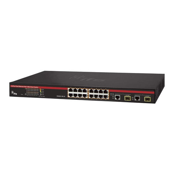
Chapter 1 Introduction Thank you for purchasing an IFS ES2402 series switch, featuring 10/100BASE-TX 802.3at PoE + 2-Port Gigabit TP/SFP Combo, with 8, 16, or 24 ports. Unless specified, the term “PoE web smart switch” mentioned in this user manual refers to the ES2402 series. -
Page 7: Product Description
Being different from the general IT industry PoE switch which usually contains 8, 16, or 24 PoE ports, the ES2402 series provides 8/16/24 802.3at PoE+ ports for catering to medium to large scale IP surveillance networks at a lower total cost. With its 5.6 Gbps / 7.2 Gbps / 8.8 Gbps high-performance switch architecture and 120 W / 220 W / 360 W... -
Page 8: Product Features
Snooping v1, v2, bandwidth control, and L2/L4 security control. The ES2402 series provides IEEE 802.1Q tagged VLAN, port-based VLAN, and MTU VLAN. Via aggregation of supporting ports, the ES2402 series allows the operation of a high- speed trunk combining multiple ports and also supports fail-over. - Page 9 Chapter 1: Introduction • Up to 8/16 IEEE 802.3af/IEEE 802.3at devices powered. • Supports PoE power up to 30.8 W for each PoE port. • Auto detects powered device (PD). • Circuit protection prevents power interference between ports. • Remote power feeding up to 100 meters. •...
-
Page 10: Product Specifications
Chapter 1: Introduction Provides port mirror (many-to-1) Port mirroring to monitor the incoming or outgoing traffic on a particular port Loop protection to avoid broadcast loops Quality of Service • Two priority queues on all switch ports • Traffic classification: Port-based priority IEEE 802.1p-based priority IP DSCP-based priority... - Page 11 Chapter 1: Introduction Switch Architecture Store-and-Forward Switch Fabric 8.8 Gbps / non-blocking Throughput 6.54 Mpps @ 64 bytes Address Table 4K entries, automatic source address learning and aging Shared Data Buffer 2.75 Mbits embedded memory for packet buffers IEEE 802.3x pause frame for full-duplex Flow Control Back pressure for half-duplex Maximum Transit Unit...
- Page 12 Chapter 1: Introduction PoE Standard IEEE 802.3af/802.3at PoE PSE PoE Power Supply Type End-span PoE Power Output Per port 54 VDC, 30.8 W (max.) Power Pin Assignment End-span: 1/2(+), 3/6(-) PoE Power Budget 380 W (max.) PoE Ability PD @ 7 W 24 units PoE Ability PD @ 15.4W 24 units...
- Page 13 Chapter 1: Introduction IEEE 802.3af Power over Ethernet IEEE 802.3at Power over Ethernet Plus Environment Temperature: 0 to 50°C Operating Relative Humidity: 5 to 95% (non-condensing) Temperature: -10 to 70°C Storage Relative Humidity: 5 to 95% (non-condensing) Product ES2402-16P-2C Hardware Specifications 10/100 Mbps Copper Ports 16 10/ 100/1000BASE-T RJ45 auto-MDI/MDI-X ports Gigabit Copper Ports...
- Page 14 Chapter 1: Introduction Power over Ethernet PoE Standard IEEE 802.3af/802.3at PoE PSE PoE Power Supply Type End-span PoE Power Output Per port 52 VDC, 30.8 W (max.) Power Pin Assignment End-span: 1/2(+), 3/6(-) PoE Power Budget 220 W (max.) PoE Ability PD @ 7 W 16 units PoE Ability PD @ 15.4W 14 units...
- Page 15 Chapter 1: Introduction IEEE 802.1D Spanning Tree Protocol IEEE 802.1w Rapid Spanning Tree Protocol IEEE 802.3af Power over Ethernet IEEE 802.3at Power over Ethernet Plus 10BASE-T: 2-Pair UTP CAT. 3, 4, 5, up to 100 meters Cable – Twisted-Pair 100BASE-TX: 2-Pair UTP CAT. 5, 5e up to 100 meters 1000BASE-T: 4-Pair UTP CAT.
- Page 16 Chapter 1: Introduction LNK/ACT (Green) 100/1000 (Green) PoE Usage LED Indicators: 30 W, 60 W, 90 W, 120 W (Orange) Dimensions (W x D x H) 330 x 153 x 44.5 mm, 1U height Weight 3.52 lb., 1.6 kg Power Consumption Max.
- Page 17 Chapter 1: Introduction Management Basic Management Interfaces Web browser, SNMP v1 Standards Conformance Regulation Compliance FCC Part 15 Class A, CE IEEE 802.3 Ethernet IEEE 802.3u Fast Ethernet IEEE 802.3ab Gigabit Ethernet IEEE 802.3z Gigabit Ethernet over Fiber-Optic IEEE 802.3x Full-duplex flow control Standards Compliance IEEE 802.1Q VLAN IEEE 802.1p QoS...
-
Page 18: Installation
Chapter 2 Installation This section describes the hardware features and installation of the PoE web smart switch on the desktop or rack mount. For easier management and control of the PoE web smart switch, familiarize yourself with its display indicators and ports. Front panel illustrations in this chapter display the unit LED indicators. - Page 19 Chapter 2: Installation ES2402-8P-2C Fast Ethernet TP interface 10/100BASE-TX Copper, RJ45 Twist-Pair: Up to 100 meters. Gigabit TP Interface 10/100/1000BASE-T Copper, RJ45 Twist-Pair: up to 100 meters. Gigabit SFP Slots 1000BASE-SX/LX mini-GBIC slot, SFP (Small Factor Pluggable) transceiver module: From 550 meters (Multi-mode fiber), up to 10/20/30/50/60/70 kilometers (Single-mode fiber).
- Page 20 Chapter 2: Installation ES2402-16P-2C ES2402-8P-2C System Color Function Green Lit: indicates that the managed switch has power. Per 10/100 Mbps port with PoE interfaces Color Function Lit: indicates the port has successfully connected to the network at 10/100 Mbps. LNK/ACT Green Blinking: indicates that the switch is actively sending or receiving data over that port.
- Page 21 Chapter 2: Installation Per 1000 Mbps SFP combo interface Color Function Blinking: indicates that the switch is actively sending or LNK/ACT Green receiving data over that port. Lit: indicates the port has successfully connected to the 1000 Green network at 1000 Mbps. PoE usage Color Function...
- Page 22 Chapter 2: Installation ES2402-8P-2C AC power receptacle For compatibility with electrical supplies in most areas of the world, the PoE web smart switch’s power supply automatically adjusts to line power in the range of 100-240 VAC and 50/60 Hz. Plug the female end of the power cord firmly into the receptacle on the rear panel of the PoE web smart switch and the other end of the power cord into an electrical outlet and then power it on.
- Page 23 Chapter 2: Installation 4. Connect one end of a standard network cable to the 10/100/1000 RJ45 ports on the front of the PoE web smart switch and the other end of the cable to the network devices such as printer servers, workstations, or routers. Note: Connection to the PoE web smart switch requires UTP Category 5 network cabling with RJ45 tips.
- Page 24 SFP port without having to power down the PoE web smart switch (see below). Approved Interlogix SFP transceivers The PoE web smart switch supports both single mode and multi-mode SFP transceivers. The following list of approved Interlogix SFP transceivers is valid as of the time of publication: Optical Optical...
- Page 25 Chapter 2: Installation Optical Optical Receiver Fiber # of Fiber Wave Operating Part # Budget Power Sensitivity Connector Fibers Type Distance Length Temperature (dBm) (dBm) (dBm) 220/550 m Multi- -40 to +75°C S35-2MLC (720 / 850 nm -14 ~ -8 mode (-40 to 167°F) 1800 ft.)
- Page 26 (dBm) (dBm) Note: We recommend the use of Interlogix SFPs on the PoE web smart switch. If you insert an SFP transceiver that is not supported, the managed switch will not recognize Note: Ports 25 to 28 are a shared SFP+ slot that supports the 10 gigabit SFP+ transceiver and gigabit SFP transceiver.
- Page 27 Chapter 2: Installation Note: Never pull out the module without making use of the lever or the push bolts on the module. Removing the module with force could damage the module and the SFP/SFP+ module slot of the managed switch. ES2402-24P-2C / ES2402-16P-2C / ES2402-8P-2C User Manual...
-
Page 28: Switch Management
Chapter 3 Switch management This chapter explains the methods that can be used to configure management access to the PoE web smart switch. It describes the types of management applications and the communication and management protocols that deliver data between the management device (workstation or personal computer) and the system. -
Page 29: Web Management
Chapter 3: Switch management The web browser interface support is embedded in the PoE web smart switch software and is available for immediate use. The advantages of these management methods are described below: Method Advantages Disadvantages Web browser • Ideal for configuring the switch •... -
Page 30: Snmp-Based Network Management
Chapter 3: Switch management SNMP-based network management Use an external SNMP-based application to configure and manage the PoE web smart switch, such as SNMP Network Manager, HP Openview Network Node Management (NNM), or What’s Up Gold. This management method requires the SNMP agent on the switch and the SNMP Network Management Station to use the same community string. -
Page 31: Web Configuration
Chapter 4 Web configuration This section introduces the configuration and functions of the web-based management interface for the PoE web smart switch. About Web-based management Web-based management of the PoE web smart switch supports Internet Explorer 8.0 or later, and can be performed from any location on the network. It is based on Java Applets with an aim to reduce network bandwidth consumption, enhance access speed, and present an easy viewing screen. - Page 32 Chapter 4: Web configuration To log into the PoE web smart switch: 1. Launch the Internet Explorer 8.0 or later web browser and type the factory default IP address http://192.168.0.100 to access the web interface. 2. When the following login screen appears, type the default username "admin" with password “admin”...
-
Page 33: Main Web
Chapter 4: Web configuration Main web page This section describes how to use the PoE web smart switch’s web browser interface for configuration and management. 1. Main menu 3. SFP port link status 2. Copper port link status 4. Main screen Panel display The web interface displays an image of the PoE web smart switch’s ports. -
Page 34: System
Chapter 4: Web configuration System Use the System menu pages to display and configure basic administrative details of the PoE web smart switch. This section contains the following main topics: System Information The switch system information is provided here. IP Configuration Configure the switch-managed IP information on this page. - Page 35 Chapter 4: Web configuration The page includes the following fields: Item Function Comment Describes the PoE web smart switch. Up to 15 characters are allowed for the Device Description. System Description Displays the current switch title. MAC Address The MAC Address of this PoE web smart switch. Hardware Version The version of hardware.
- Page 36 Chapter 4: Web configuration The page includes the following fields: Item Function IP Address Provide the IP address of this switch in dotted decimal notation. Subnet Mask Provide the subnet mask of this switch in dotted decimal notation. Gateway Provide the IP address of the router in dotted decimal notation. IP Configure Indicate the IP address mode operation.
- Page 37 Chapter 4: Web configuration Factory default Reset the PoE web smart switch to factory default mode on this page. Click the Factory Default button to reset the switch to factory default. After finishing this operation, the web login screen appears. Use the default user name and password to continue with PoE web smart switch management.
- Page 38 Chapter 4: Web configuration 2. Click to continue. The following screen appears. 3. The following screen appears. Click Browse to find the firmware file on the administrator computer, and then click Update to begin the firmware upgrade process. 4. When the firmware upgrade is complete, click Continue and wait for the system to reboot.
-
Page 39: Port Management
Chapter 4: Web configuration Reboot The Reboot page permits the device to be rebooted from a remote location. After clicking the Confirm button to restart, log in to the web interface approximately 60 seconds later to continue with switch management. Buttons •... - Page 40 Chapter 4: Web configuration The page includes the following fields: Object Description Tx/Rx Ability Indicates the port state operation. Selections include: Enable – Start up the port manually. Disable – Shut down the port manually. Auto-Negotiation When set as Auto, the speed and duplex mode are negotiated automatically.
- Page 41 Chapter 4: Web configuration Object Description Full - Force sets Full-Duplex mode. Half - Force sets Half-Duplex mode. Pause When Auto Speed is selected for a port, this section indicates the flow control capability that is advertised to the link partner. When a fixed-speed setting is selected, that is what is used.
- Page 42 Chapter 4: Web configuration The traffic to be copied to the mirror port is selected as follows: • All frames received on a given port (also known as ingress or source mirroring). • All frames transmitted on a given port (also known as egress or destination mirroring).
- Page 43 Chapter 4: Web configuration Bandwidth control The Bandwidth Control and Status pages allow you to select the ingress and egress bandwidth preamble. The page includes the following fields: Object Description Port No Select a port number for this drop-down list to enable the function. Tx Rate Configure the Tx rate for the selected port.
- Page 44 Chapter 4: Web configuration • Click LoadDefault to restore default settings The page includes the following fields: Object Description Port No The switch port number of the logical port. Tx Rate Display the current Tx rate limitation. Rx Rate Display the current Rx rate limitation. Link Speed Display the current link speed information.
- Page 45 Chapter 4: Web configuration The page includes the following fields: Object Description Threshold Configure the Broadcast Threshold for the selected port. Valid values are in the range from 1 to 63; Per unit is 50 us for Gigabit speed, 500 us for 100 Mbps speed and 5000us for 10 Mbps speed Enable Port Select port number for this checkbox list to enable the function.
-
Page 46: Vlan
Chapter 4: Web configuration The page includes the following fields: Object Description Counter Mode Selection Configure the counter mode using this drop-down list. Options: Transmit Packet & Receive Packet The total number of octets transmitted / received out of the interface, including framing characters. - Page 47 Chapter 4: Web configuration On port-based VLAN, NICs do not need to be able to identify 802.1Q tags in packet headers. NICs send and receive normal Ethernet packets. If the packet's destination lies on the same segment, communications take place using normal Ethernet protocols. Even though this is always the case, when the destination for a packet lies on another switch port, VLAN considerations come into play to decide if the packet is dropped by the switch or delivered.
- Page 48 Chapter 4: Web configuration This section contains the following main topics: VLAN Basic Information Configures the management VLAN. VLAN Port Configuration Creates the VLAN group. Multi to 1 Setting Configures mode and PVID on the VLAN port. VLAN basic information The VLAN Mode page displays basic information on the VLAN type supported by the PoE web smart switch.
- Page 49 Chapter 4: Web configuration The VLAN Mode screen changes to the Tag Based VLAN mode view: The page includes the following fields: Object Description VLAN Mode Display the current VLAN mode used by the PoE web smart switch. Options: Tag-based VLAN Port-based VLAN VLAN Tag Mode Configure VLAN tag mode.
- Page 50 Chapter 4: Web configuration Port-based VLAN mode The page includes the following fields: Object Description Port Select a port number from the drop-down list to enable the function. Destination Port Enable / Disable the selected port to join its VLAN member. Buttons •...
- Page 51 Chapter 4: Web configuration The page includes the following fields: Object Description Allow to assign PVID(Port VLAN ID) for selected port. The PVID will be inserted into all untagged frames entering the ingress port. The PVID must be the same as the VLAN ID whose port belongs to VLAN group, or the untagged traffic will be dropped.
-
Page 52: Quality Of Service (Qos)
Chapter 4: Web configuration Quality of Service (QoS) QoS overview Quality of Service (QoS) is an advanced traffic prioritization feature that allows you to establish control over network traffic. QoS permits the assignment of various grades of network service to different types of traffic such as multi-media, video, protocol-specific, time critical, and file-backup traffic. - Page 53 Chapter 4: Web configuration The page includes the following fields: Object Description Mode Configure QoS mode. Selections include: First-In-First-Out All-High-before-Low Weighted-Round-Robin Class of service configuration Configure class of service on the Class of Service Configuration page. The page includes the following fields: Object Description Mode...
- Page 54 Chapter 4: Web configuration TCP/UDP port-based QoS Configure TCP/UDP port-based options and functions on the TCP/UDP Port Based QoS page. ES2402-24P-2C / ES2402-16P-2C / ES2402-8P-2C User Manual...
-
Page 55: Security
Chapter 4: Web configuration The page includes the following fields: Object Description Protocol Select IP port number value for the list. Option Select a QoS option from the drop-down lists. Selections include: F-I-F-O – The output queue assignment is determined with first- come, first-served (FCFS) behavior. - Page 56 Chapter 4: Web configuration The page includes the following fields: Object Description Select Port Select a port from this drop-down list. Binding Set the MAC address binding function from this drop-down list. Options: Enable Disable MAC address Configure the binding MAC address for this table. Buttons •...
- Page 57 Chapter 4: Web configuration The page includes the following fields: Object Description Function Enable Configure the TCP/UDP filter function by making one of the following selections: Enable Disable Port Filtering Rule Configure the Port Filtering Rule function by making one of the following selections.
-
Page 58: Spanning Tree Protocol (Stp)
Chapter 4: Web configuration Spanning Tree Protocol (STP) Theory STP can be used to detect and disable network loops, and to provide backup links between switches, bridges, or routers. This allows the switch to interact with other bridging devices in the network to ensure that only one route exists between any two stations on the network, and provides backup links that automatically take over when a primary link goes down. - Page 59 Chapter 4: Web configuration STP communicates between switches on the network using Bridge Protocol Data Units (BPDUs). Each BPDU contains the following information: • The unique identifier of the switch that the transmitting switch currently believes is the root switch. •...
- Page 60 Chapter 4: Web configuration Listening – The port is waiting to receive BPDU packets that may tell the port to go • back to the blocking state. Learning – The port is adding addresses to its forwarding database, but not yet •...
- Page 61 Chapter 4: Web configuration STP parameters STP operation levels The managed switch allows for two levels of operation: the switch level and the port level. The switch level forms a spanning tree consisting of links between one or more switches. The port level constructs a spanning tree consisting of groups of one or more ports.
- Page 62 Chapter 4: Web configuration Default spanning-tree configuration Feature Default Value Enable state STP disabled for all ports Port priority Port cost Bridge Priority 32,768 User-changeable STA parameters The factory default settings for the switch should cover the majority of installations. It is advisable to keep the default settings as set at the factory unless it is absolutely necessary.
- Page 63 Chapter 4: Web configuration If switch A broadcasts a packet to switch B, switch B broadcasts to switch C, and switch C broadcasts back to switch A and so on. The broadcast packet will be passed indefinitely in a loop, potentially causing a network failure. In this example, STP breaks the loop by blocking the connection between switch B and C.
- Page 64 Chapter 4: Web configuration The switch with the lowest bridge ID (switch C) was elected the root bridge, and the ports were selected to give a high port cost between switches B and C. The two (optional) Gigabit ports (default port cost = 20,000) on switch A are connected to one (optional) Gigabit port on both switch B and C.
- Page 65 Chapter 4: Web configuration The page includes the following fields: Object Description STP Mode Select the STP mode from this drop-down list. Disable RSTP Bridge Priority (0~61440) Controls the bridge priority. Lower numeric values have higher priority. The bridge priority plus the MSTI instance number, concatenated with the 6-byte MAC address of the switch, forms a Bridge Identifier.
- Page 66 Chapter 4: Web configuration The Bridge Status page appears as follows: The page includes the following fields: Object Description STP Mode Displays STP Mode status Bridge ID Displays the Bridge ID Hello Time Displays the Hello Time Max Age Displays the Max Age Forward Delay Displays the Forward Delay The Root Status page appears as follows:...
- Page 67 Chapter 4: Web configuration The page includes the following fields: Object Description Port No. Select the port number from this drop down list. · Priority (0~240) Controls the port priority. This can be used to control priority of ports having identical port cost. Default: 128 Range: 0-240, in steps of 16 ·...
- Page 68 Chapter 4: Web configuration The page includes the following fields: Object Description Path Cost Display the STP Mode Status Priority Display the Port Priority Status Display the Port Status Status Display the Port Status Buttons • Click Submit to apply changes. Loopback detection The loopback detection function avoids user network loops.
-
Page 69: Link Aggregation
Chapter 4: Web configuration The Loopback Detection Status page appears as follows: The page includes the following fields: Object Description Status Displays loopback detection status. Buttons • Click Submit to apply changes. • Click Reset All Ports to reset the status. Link aggregation Port Aggregation optimizes port usage by linking a group of ports together to form a single Link Aggregated Group (LAG). - Page 70 Chapter 4: Web configuration Aggregated links can be assigned manually (Port Trunk) or automatically by enabling Link Aggregation Control Protocol (LACP) on the relevant links. Aggregated links are treated by the system as a single logical port. Specifically, the aggregated link has similar port attributes to a non-aggregated port, including auto- negotiation, speed, duplex setting, etc.
- Page 71 Chapter 4: Web configuration use the link aggregation configuration menu to specify the link aggregation on the devices at both ends. When using a port link aggregation, note that: • The ports used in a link aggregation must all be of the same media type (RJ45, 100 Mbps fiber).
- Page 72 Chapter 4: Web configuration Trunking setting Configure link aggregation settings on the Trunking Setting page. The page includes the following fields: Object Description System Priority Controls the priority of the port. If the LACP partner wants to form a larger group than is supported by this device, this parameter controls which ports will be active and which ports will be in a backup role.
-
Page 73: Power Over Ethernet (Poe)
Chapter 4: Web configuration Object Description Member Select a port number from this drop-down list to establish link aggregation. State Indicates the LAG status operation. Selections include: Enabled – Start up the LAG manually. Disabled – Shut down the LAG manually. Type Indicates the trunk type. - Page 74 Chapter 4: Web configuration A PD will return Class 0 to 4 in accordance with the maximum power draw as specified below: Class Usage Range of maximum power used by the PD Class Description 12.95 W (or to 15.4 W for AF mode) Mid power or High power Default 25.5 W (or to 30.8 W for AT mode)
- Page 75 Chapter 4: Web configuration PoE status In a PoE system, operating power is applied from a power source (PSU-power supply unit) over the LAN infrastructure to powered devices (PDs), which are connected to ports. Under some conditions, the total output power required by PDs can exceed the maximum available power provided by the PSU.
- Page 76 Chapter 4: Web configuration The page includes the following fields: Object Description Power Supply Budget Configure the total W usage of the switch. ES2402-24P-2C offers 380 W PoE power budget maximum. ES2402-16-2C offers 220 W PoE power budget maximum. ES2402-8P-2C offers 125 W PoE power budget maximum. System Operation Status Display the current System Operation Status.
- Page 77 Chapter 4: Web configuration Object Description From class1 to class3 level on the 802.3at mode will be reserved with the same PoE power with 802.3af mode. Priority The Priority represents PoE ports priority. There are three levels of power priority named 1(Low), 2(High) and 3(Critical). The priority is used in the case when total power consumption has been over total power budget.
- Page 78 Power Used[W] The Power Used shows how much power the PD currently is using. Power Allocation [W] Display PoE port maximum output value of PoE Port Setting. ES2402 SERIES offers 30 W of power allocation only. Buttons • Click Update to apply changes.
-
Page 79: Configuration Backup/Upload
Chapter 4: Web configuration The PoE Port Sequential Setting Status screen appears as follows: The page includes the following fields: Object Description Port This is the logical port number for this row. Delay Mode Display delay mode of Port Sequential. Delay Time [S] Display delay interval time of Port Sequential. -
Page 80: Miscellaneous Operation
Chapter 4: Web configuration The page includes the following fields: Object Description Backup (Switch PC) Permits backup of the current configuration to a computer. Recovery (PC Switch) Permits recovery of the current configuration to thr switch. Use the Browse... button to select file which you want to reload to the switch and type in the switch password. -
Page 81: Simple Network Management Protocol (Snmp)
Chapter 4: Web configuration Object Description include: Disabled: Disable Output Queue Aging Time operation 200: Configure 200 ms for the Output Queue Aging Time. 400: Configure 400 ms for the Output Queue Aging Time. 600: Configure 600 ms for the Output Queue Aging Time. 800: Configure 800 ms for the Output Queue Aging Time. - Page 82 Chapter 4: Web configuration • Agents: Agents are software modules that reside in network elements. They collect and store management information such as the number of error packets received by a network element. • Management information base (MIB): An MIB is a collection of managed objects residing in a virtual information store.
-
Page 83: Logout
Chapter 4: Web configuration The page includes the following fields: Object Description Community Name A string identifying the SNMP Community name that this entry should belong to. Access Right Indicates the SNMP community type operation. Possible types are: RO=Read Only: Set access string type in read-only mode. RW=Read/Write: Set access string type in read-write mode. - Page 84 Chapter 4: Web configuration Buttons • Click Logout to apply logout. ES2402-24P-2C / ES2402-16P-2C / ES2402-8P-2C User Manual...
-
Page 85: Switch Operation
Chapter 5: Switch operation Chapter 5 Switch operation Address table The switch is implemented with an address table. This address table is composed of many entries. Each entry is used to store the address information of some node in network, including MAC address, port number, etc. This information comes from the learning process of the managed switch. -
Page 86: Auto-Negotiation
Chapter 5: Switch operation transmission. Therefore, no erroneous packets will occur, making it the best choice when a network needs efficiency and stability. The switch scans the destination address from the packet header and searches the routing table provided for the incoming port and forwards the packet if required. The fast forwarding makes the switch attractive for connecting servers directly to the network, thereby increasing throughput and availability. -
Page 87: Poe Overview
Chapter 6 PoE overview What is PoE? PoE is an abbreviation for Power over Ethernet. PoE technology permits a system to pass data and electrical power safely on an Ethernet UTP cable. The IEEE standard for PoE technology requires a category 5 cable or higher for high power PoE levels, but can operate with a category 3 cable for low power levels. - Page 88 Chapter 6: PoE overview 15.40 W. A later specification, IEEE 802.3at, offers 25.50 W. When the device is a switch, it is commonly called an end-span, although IEEE 802.3af refers to it as endpoint. Otherwise, if it's an intermediary device between a non PoE capable switch and a PoE device, it's called a mid-span.
- Page 89 Chapter 7 Troubleshooting This chapter contains information to help you solve issues. If the managed switch is not functioning properly, ensure that it was set up according to the instructions in this manual. Issue Solution The link LED does not illuminate Check the cable connection and remove duplex mode of the managed switch.
- Page 90 Appendix A Networking connection RJ45 port pin assignments – 1000Mbps, 1000BASE-T Pin number MDI-X BI_DA+ BI_DB+ BI_DA- BI_DB- BI_DB+ BI_DA+ BI_DC+ BI_DD+ BI_DC- BI_DD- BI_DB- BI_DA- BI_DD+ BI_DC+ BI_DD- BI_DC- Implicit implementation of the crossover function within a twisted-pair cable, or at a wiring panel, while not expressly forbidden, is beyond the scope of this standard.
- Page 91 Appendix A: Networking connection There are eight wires on a standard UTP/STP cable and each wire is color-coded. The following shows the pin allocation and the color of the straight cable and crossover cable connection: Straight Cable SIDE 1 SIDE 2 SIDE 1 1 = White / Orange 1 = White / Orange...
Need help?
Do you have a question about the ES2402 Series and is the answer not in the manual?
Questions and answers