Table of Contents
Advertisement
Quick Links
Advertisement
Table of Contents

Related Manuals for Interlogix NS4750-24S-4T-4X


Summary of Contents for Interlogix NS4750-24S-4T-4X
- Page 1 NS4750-24S-4T-4X User Manual P/N 1702826 • REV 00.01 • ISS 14JUL14...
- Page 2 © 2014 United Technologies Corporation Copyright Interlogix is part of UTC Building & Industrial Systems,Inc. a unit of United Technologies Corporation. All rights reserved. The NS4750-24S-4T-4X name and logo are trademarks of United Trademarks and patents Technologies. Other trade names used in this document may be trademarks or registered trademarks of the manufacturers or vendors of the respective products.
-
Page 3: Table Of Contents
TABLE OF CONTENTS 1. INTRODUCTION........................10 1.1 Packet Contents ............................10 1.2 Product Descriptions..........................11 1.3 How to Use This Manual..........................14 1.4 Product Features............................15 1.5 Product Specifications ..........................18 2. INSTALLATION ........................21 2.1 Hardware Descriptions ..........................21 2.1.1 Front Panel................................21 ... - Page 4 4.2 System.................................48 4.2.1 System Information..............................48 4.2.2 IP Configuration..............................49 4.2.3 IP Status ................................52 4.2.4 Users Configuration.............................53 4.2.5 Privilege Levels ..............................55 4.2.6 NTP Configuration ...............................58 4.2.7 Time Configuration ..............................59 4.2.8 UPnP ...................................60 4.2.9 DHCP Relay ................................62 ...
- Page 5 4.3.5.5 SNMPv3 Access............................98 4.4 Port Management .............................100 4.4.1 Port Configuration.............................. 100 4.4.2 Port Statistics Overview............................. 103 4.4.3 Detailed Port Statistics............................104 4.4.4 SFP Information..............................106 4.4.5 Port Mirror ................................. 108 4.5 Link Aggregation............................111 4.5.1 Static Aggregation..............................
- Page 6 4.7.8 Port Status................................. 176 4.7.9 Port Statistics..............................178 4.8 Multicast..............................179 4.8.1 IGMP Snooping ..............................179 4.8.2 Profile Table............................... 184 4.8.3 Address Entry ..............................185 4.8.4 IGMP Snooping Configuration ........................... 187 4.8.5 IGMP Snooping VLAN Configuration......................... 189 ...
- Page 7 4.9.12 QoS Status ..............................240 4.9.13 Storm Control Configuration ..........................242 4.9.14 WRED ................................244 4.9.15 QoS Statistics ..............................246 4.9.16 Voice VLAN Configuration ..........................248 4.9.17 Voice VLAN OUI Table ............................ 251 4.10 Access Control Lists..........................253 4.10.1 Access Control List Status ..........................
- Page 8 4.13.1 MAC Address Table Configuration........................338 4.13.2 MAC Address Table Status ..........................341 4.13.3 Dynamic ARP Inspection Table........................342 4.13.4 Dynamic IP Source Guard Table ........................343 4.14 LLDP ................................345 4.14.1 Link Layer Discovery Protocol ......................... 345 ...
- Page 9 4.19.5 Ring Wizard..............................401 4.19.6 Ring Wizard Example: ............................. 402 5. SWITCH OPERATION ....................... 405 5.1 Address Table ............................405 5.2 Learning ..............................405 5.3 Forwarding & Filtering..........................405 5.4 Store-and-Forward ...........................405 5.5 Auto-Negotiation ............................406 6.
-
Page 10: Introduction
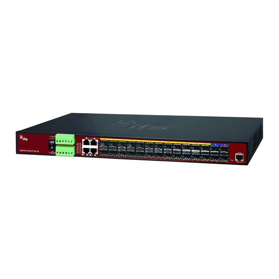
1. INTRODUCTION IFS NS4750-24S-4T-4X is a 24-port 100/1000Base-X SFP + 4-port 10G SFP+ L2/L4 Managed Switch. The NS4750-24S-4T-4X is all multiple Gigabit SFP mini-GBIC slots switch plus four Gigabit Copper combo ports with connective ability and robust layer 2 features. The description of the NS4750-24S-4T-4X is shown below:... -
Page 11: Product Descriptions
1.2 Product Descriptions Multiple SFP Fiber Port Switch for Increasing Long-reach Networking of Enterprise, Telecoms and Campus The NS4750 is equipped with advanced management functions and provides 24 100/1000Mbps dual speed SFP fiber ports, 4 10Gbps dual speed fiber ports and 4 10/100/1000Mbps TP/SFP ports delivered in a rugged strong case. It is capable of providing non-blocking switch fabric and wire-speed throughput as high as 128Gbps in the temperature range from -10 to 60 degrees C without any packet loss and CRC error, which greatly simplify the tasks of upgrading the enterprise LAN for catering to increasing bandwidth demands. - Page 12 Digital Input and Digital Output for External Alarm IFS NS4750 supports Digital Input, and Digital Output on the front panel. This external alarm offers technicians the ability to use Digital Input to detect, and log external device status (such as door intrusion detector) for the alarm. As Digital Output could be used to alarm if the NS4750 has port link down, link up or power failure.
- Page 13 Flexible and Extendable Solution The 24 mini-GBIC slots built in the NS4750 support dual-speed, 100Base-FX and 1000Base-SX/LX SFP (Small Form-factor Pluggable) fiber-optic modules, meaning the administrator now can flexibly choose the suitable SFP transceiver according to the transmission distance or the transmission speed required to extend the network efficiently. The NS4750 supports SFP-DDM (Digital Diagnostic Monitor) function that can easily monitor real-time parameters of the SFP for network administrator, such as optical output power, optical input power, temperature, laser bias current, and transceiver supply voltage.
-
Page 14: How To Use This Manual
1.3 How to Use This Manual This User Manual is structured as follows: Section 2, INSTALLATION The section explains the functions of the Managed Switch and how to physically install the Managed Switch. Section 3, SWITCH MANAGEMENT The section contains the information about the software function of the Managed Switch. Section 4, WEB CONFIGURATION The section explains how to manage the Managed Switch by Web interface. -
Page 15: Product Features
1.4 Product Features Physical Port 24 100/1000Base-X SFP mini-GBIC slots 4 1/10GBase-SR/LR SFP mini-GBIC slots 4 10/100/1000Base-T Gigabit Ethernet RJ-45 combo ports One RJ-45 Console Interface for Basic Management and Setup Redundant Power System ... - Page 16 MAC-based VLAN Voice VLAN Supports Spanning Tree Protocol STP, IEEE 802.1D Spanning Tree Protocol RSTP, IEEE 802.1w Rapid Spanning Tree Protocol MSTP, IEEE 802.1s Multiple Spanning Tree Protocol, Spanning Tree by VLAN BPDU Guard ...
- Page 17 Link Layer Discovery Protocol (LLDP) Protocol SFP-DDM (Digital Diagnostic Monitor) Cable Diagnostic technology provides the mechanism to detect and report potential cabling issues Reset Button for System Reboot or Reset to Factory Default INTERLOGIX Smart Discovery Utility for Deploy Management...
-
Page 18: Product Specifications
1.5 Product Specifications Product NS4750-24S-4T-4X Hardware Specification 24 1000Base-SX/LX/BX SFP interfaces SFP/mini-GBIC Slots (Compatible with 100Base-FX SFP Transceiver) 4 1/10GBase-SR/LR SFP+ slots 10Gbps Fiber Ports 4 10/ 100/1000Base-T TP/SFP combo ports Copper Ports 1 x RS-232 RJ45 serial port (115200, 8, N, 1) - Page 19 802.1Q Tagged based VLAN Port-based VLAN Q-in-Q VLAN Private VLAN Edge (PVE) Up to 256 VLAN groups, out of 4094 VLAN IDs IEEE 802.3ad LACP / Static Trunk Port Trunking 12 groups of 16-port trunk support Traffic classification based, Strict priority and WRR 4-level priority for switching - Port Number - 802.1p priority...
- Page 20 IEEE 802.1p Class of service IEEE 802.1Q VLAN tagging IEEE 802.1x Port Authentication Network Control IEEE 802.1ab LLDP ITU G.8032 Ethernet Ring Protection Switching RFC 768 UDP RFC 793 TFTP RFC 791 IP RFC 792 ICMP RFC 2068 HTTP RFC 1112 IGMP version 1 RFC 2236 IGMP version 2 RFC 3376 IGMP version 3 Environment...
-
Page 21: Installation
2.1.1 Front Panel Figure 2-1 shows the front panel of Managed Switch. Figure 2-1: NS4750-24S-4T-4X Switch Front Panel ■ Gigabit TP interface 10/100/1000Base-T Copper, RJ-45 Twist-Pair: Up to 100 meters. ■ Gigabit SFP slots 1000Base-SX/LX mini-GBIC slot, SFP (Small Factor Pluggable) Transceiver Module supports from 550 meters (Multi-mode Fiber), up to 10/30/50/70/120 kilometers (Single Mode Fiber). - Page 22 ■ Reset button On the front panel, the reset button is designed for rebooting the Managed Switch without turning off and on the power. The following is the summary table of reset button functions: Reset Button (Press and Release) Function <...
-
Page 23: Led Indications
Plug the female end of the power cord firmly into the receptable on the front panel of the Managed Switch. Plug the other end of the power cord into an electric service outlet and then the power will be ready. The device is a power-required device, which means it will not work till it is powered. - Page 24 Lights Indicates that Fan 2 has stopped. FAN2 Green Lights Indicates that Switch AC/DC or port has failed. Fault Green Indicates that the Switch is powered on. Lights Green Indicates the system is running under booting procedure. Blinks 10/100/1000Base-T interfaces for port1 to port24 SFP slot Color Function Indicates the link through that SFP port is successfully established with speed...
-
Page 25: Wiring The Ac Power Input
Insert positive / negative DC power wires into contacts 1 and 2 for DC POWER 1, or 5 and 6 for DC POWER 2. Figure 2-3: NS4750-24S-4T-4X Upper Panel Tighten the wire-clamp screws for preventing the wires from loosening. -
Page 26: Wiring The Faulty Alarm Contact
DC 1 DC 2 Figure 2-4 6-Pin Terminal Block Power Wiring Input 1. The wire gauge for the terminal block should be in the range of 12 ~ 24 AWG. 2. When performing any of the procedures like inserting the wires or tighten the wire-clamp screws, make sure the power is OFF to prevent from getting an electric shock. -
Page 27: Wiring The Digital Input / Output
The 6-contact terminal block connector on the front panel of NS4750-24S-4T-4X is used for Digital Input and Digital Output. Please follow the steps below to insert wire. The NS4750-24S-4T-4X offers two DI and DO groups. 1 and 2 are DI groups, 3 and 4 are DO groups and 5 and 6 are GND (ground). - Page 28 There are two Digital Input groups for you to monitor two different devices. The following topology shows how to wire DI0 and DI1. We use the NS4750-24S-4T-4X to be an example for describing DI application. Figure 2-7 Wires DI0 and DI1 to Open Detector...
- Page 29 There are two Digital Output groups for you to sense NS4750-24S-4T-4X port failure or power failure and issue a high or low signal to external device. The following topology shows how to wire DO0 and DO1. Figure 2-8 Wires DO0 and DO1 to Open Detector...
-
Page 30: Installing The Managed Switch
2.2 Installing the Managed Switch This section describes how to install your Managed Switch and make connections to the Managed Switch. Please read the following topics and perform the procedures in the order being presented. To install your Managed Switch on a desktop or shelf, simply complete the following steps. -
Page 31: Rack Mounting
Connecting to the Managed Switch requires UTP Category 5 network cabling with RJ-45 tips. For more information, please see the Cabling Specification in Appendix A. Supply power to the Managed Switch. Step5: Connect one end of the power cable to the Managed Switch. Connect the power plug of the power cable to a standard wall outlet. - Page 32 Figure 2-6 Mounting the Managed Switch on a Rack Step6: Proceeds with steps 4 and 5 of session 2.2.1 Desktop Installation to connect the network cabling and supply power to the Managed Switch.
-
Page 33: Cabling
2.3 Cabling 10/100/1000Base-T and 100Base-FX / 1000Base-SX/LX All 10/100/1000Base-T ports come with auto-negotiation capability. They automatically support 1000Base-T, 100Base-TX and 10Base-T networks. Users only need to plug a working network device into one of the 10/100/1000Base-T ports, and then turn on the Managed Switch. The port will automatically run in 10Mbps, 20Mbps, 100Mbps or 200Mbps and 1000Mbps or 2000Mbps after the negotiation with the connected device. -
Page 34: Installing The Sfp Transceiver
Figure 2-9: Plugging in the SFP Transceiver Approved INTERLOGIX SFP Transceivers INTERLOGIX Managed Switch supports 100/1000 dual mode with both single mode and multi-mode SFP transceivers. The following list of approved INTERLOGIX SFP transceivers is correct at the time of publication: Gigabit SFP Transceiver Modules SFP-Port 1000Base-T Module –... - Page 35 * 62.5/125um fiber only supports 33meter, for 300m use OM3 50/125um. It is recommended to use INTERLOGIX SFPs on the Managed Switch. If you insert an SFP transceiver that is not supported, the Managed Switch will not recognize it.
- Page 36 Check the fiber-optic cable type that matches the SFP transceiver model. To connect to 1000Base-SX SFP transceiver, use the multi-mode fiber cable with one side being the male duplex LC connector type. To connect to 1000Base-LX SFP transceiver, use the single-mode fiber cable with one side being the male duplex LC connector type.
-
Page 37: Removing The Module
2.3.2 Removing the Module Make sure there is no network activity by checking with the network administrator, or through the management interface of the switch/converter (if available) to disable the port in advance. Remove the Fiber Optic Cable gently. Lift up the lever of the MGB module and turn it to a horizontal position. Pull out the module gently through the lever. -
Page 38: Switch Management
3. SWITCH MANAGEMENT This chapter explains the methods that you can use to configure management access to the Managed Switch. It describes the types of management applications and the communication and management protocols that deliver data between your management device (workstation or personal computer) and the system. It also contains information about port connection options. -
Page 39: Management Access Overview
3.2 Management Access Overview The Managed Switch gives you the flexibility to access and manage it using any or all of the following methods: Remote Telnet Interface Web browser Interface An external SNMP-based network management application The Remote Telnet and Web browser interface support are embedded in the Managed Switch software and are available for immediate use. -
Page 40: Cli Mode Management
There are two ways for CLI mode management, one is remote telnet, and the other is operating from console port. Remote telnet is an IP-based protocol, and console port is for user to operate the NS4750-24S-4T-4X on local only, however their operation is the same. -
Page 41: Web Management
3.4 Web Management The Managed Switch offers management features that allow users to manage the Managed Switch from anywhere on the network through a standard browser such as Microsoft Internet Explorer. After you set up your IP address for the Managed Switch, you can access the Managed Switch’s Web interface applications directly in your Web browser by entering the IP address of the Managed Switch. -
Page 42: Snmp-Based Network Management
3.5 SNMP-based Network Management You can use an external SNMP-based application to configure and manage the Managed Switch, such as SNMP Network Manager, HP Openview Network Node Management (NNM) or What’s Up Gold. This management method requires the SNMP agent on the Managed Switch and the SNMP Network Management Station to use the same community string. This management method, in fact, uses two community strings: the get community string and the set community string. -
Page 43: Web Configuration
4. WEB CONFIGURATION This section introduces the configuration and functions of the Web-based management. About Web-based Management The Managed Switch offers management features that allow users to manage the Managed Switch from anywhere on the network through a standard browser such as Microsoft Internet Explorer. The Web-Based Management supports Internet Explorer 7.0. - Page 44 Logging on the Managed Switch Use Internet Explorer 7.0 or above Web browser. Enter the factory-default IP address to access the Web interface. The factory-default IP Address is shown as follows: http://192.168.0.100 When the following login screen appears, please enter the default username "admin" with password “admin” (or the username/password you have changed via console) to login the main screen of Managed Switch.
- Page 45 After entering the username and password, the main screen appears as shown in Figure 4-1-3. Figure 4-1-3: Default Main Page Now, you can use the Web management interface to continue the switch management or manage the Managed Switch by Web interface.
-
Page 46: Main Web Page
4.1 Main Web Page The Managed Switch provides a Web-based browser interface for configuring and managing it. This interface allows you to access the Managed Switch using the Web browser of your choice. This chapter describes how to use the Managed Switch’s Web browser interface to configure and manage it. - Page 47 Main Menu Using the onboard web agent, you can define system parameters, manage and control the Managed Switch, and all its ports, or monitor network conditions. Via the Web-Management, the administrator can setup the Managed Switch by selecting the functions those listed in the Main Function. The screen in Figure 4-1-5 appears.
-
Page 48: System
4.2 System Use the System menu items to display and configure basic administrative details of the Managed Switch. Under the System the following topics are provided to configure and view the system information. 4.2.1 System Information The System Info page provides information for the current device information. System Info page helps a switch administrator to identify the hardware MAC address, software version and system uptime. -
Page 49: Ip Configuration
Power The AC Power, Power 1 and Power 2 ON/OFF Status display. Temperature The temperature shows current of the switch inside temperature status. The current (GMT) system time and date. The system time is obtained through the System Date configured SNTP Server, if any. - Page 50 The Current column is used to show the active IP configuration. Object Description Configure whether the IP stack should act as a Host or a IP Configurations Mode Router. In Host mode, IP traffic between interfaces will not be routed.
- Page 51 The IPv6 network mask, in number of bits (prefix length). Valid Mask values are between 1 and 128 bits for a IPv6 address. Length Select this option to delete an existing IP route. IP Routes Delete The destination IP network or host address of this route. Valid Network format is dotted decimal notationor a valid IPv6 notation.
-
Page 52: Ip Status
4.2.3 IP Status IP Status displays the status of the IP protocol layer. The status is defined by the IP interfaces, the IP routes and the neighbour cache (ARP cache) status. The screen in Figure 4-2-3 appears. Figure 4-2-3: IPv6 Configuration Page Screenshot The page includes the following fields: Object Description... -
Page 53: Users Configuration
Buttons : Click to save changes. : Click to undo any changes made locally and revert to previously saved values. : Click to renew IPv6 Auto Configuration. This button is only available if IPv6 Auto Configuration is enabled. 4.2.4 Users Configuration This page provides an overview of the current users. - Page 54 Buttons : Click to add a new user. Add / Edit User This page configures a user – add, edit or delete user. Figure 4-2-5: Add / Edit User Configuration Page Screenshot The page includes the following fields: Object Description ...
-
Page 55: Privilege Levels
: Click to save changes. : Click to undo any changes made locally and revert to previously saved values. : Click to undo any changes made locally and return to the Users. : Delete the current user. This button is not available for new configurations (Add new user) Figure 4-2-6: User Configuration Page Screenshot If you forget the new password after changing the default password, please press the “Reset”... - Page 56 Figure 4-2-7: Privilege Levels Configuration Page Screenshot...
- Page 57 The page includes the following fields: Object Description Group Name The name identifying the privilege group. In most cases, a privilege level group consists of a single module (e.g. LACP, RSTP or QoS), but a few of them contains more than one. The following description defines these privilege level groups in details: ...
-
Page 58: Ntp Configuration
4.2.6 NTP Configuration Configure NTP on this page. NTP is an acronym for Network Time Protocol, a network protocol for synchronizing the clocks of computer systems. NTP uses UDP (data grams) as transport layer. You can specify NTP Servers and set GMT Time zone. The NTP Configuration screen in Figure 4-2-8 appears. -
Page 59: Time Configuration
: Click to save changes. : Click to undo any changes made locally and revert to previously saved values. 4.2.7 Time Configuration Configure Time Zone on this Page. A Time Zone is a region that has a uniform standard time for legal, commercial, and social purposes. -
Page 60: Upnp
Time Zone Lists various Time Zones world wide. Select appropriate Time Zone from the drop down and click Save to set. User can set the acronym of the time zone. This is a User configurable acronym Acronym to identify the time zone. ( Range : Up to 16 characters ) ... - Page 61 Figure 4-2-10: UPnP Configuration Page Screenshot The page includes the following fields: Object Description Mode Indicates the UPnP operation mode. Possible modes are: Enabled: Enable UPnP mode operation. Disabled: Disable UPnP mode operation. When the mode is enabled, two ACEs are added automatically to trap UPNP related packets to CPU.
-
Page 62: Dhcp Relay
Figure 4-2-11: UPnP Devices shows on Windows My Network Places 4.2.9 DHCP Relay Configure DHCP Relay on this page. DHCP Relay is used to forward and to transfer DHCP messages between the clients and the server when they are not on the same subnet domain. The DHCP option 82 enables a DHCP relay agent to insert specific information into a DHCP request packets when forwarding client DHCP packets to a DHCP server and remove the specific information from a DHCP reply packets when forwarding server DHCP packets to a DHCP client. - Page 63 Figure 4-2-12: DHCP Relay Configuration Page Screenshot The page includes the following fields: Object Description Relay Mode Indicates the DHCP relay mode operation. Possible modes are: Enabled: Enable DHCP relay mode operation. When enable DHCP relay mode operation, the agent forward and to transfer DHCP messages between the clients and the server when they are not on the same subnet domain.
-
Page 64: Dhcp Relay Statistics
that already contains it. Drop: Drop the package when receiving a DHCP message that already contains relay information. Buttons : Click to save changes. : Click to undo any changes made locally and revert to previously saved values. 4.2.10 DHCP Relay Statistics This page provides statistics for DHCP relay. -
Page 65: Cpu Load
Remote ID Receive Bad Circuit ID The number of packets whose Circuit ID option did not match known circuit ID. Receive Bad Remote The number of packets whose Remote ID option did not match known Remote Client Statistics Object Description ... - Page 66 Figure 4-2-13: CPU Load Page Screenshot Buttons Auto-refresh : Check this box to refresh the page automatically. Automatic refresh occurs every 3 seconds. If your browser cannot display anything on this page, please download Adobe SVG tool and install it in your computer.
-
Page 67: System Log
4.2.12 System Log The switch system log information is provided here. The System Log screen in Figure 4-2-15 appears. Figure 4-2-15: System Log Page Screenshot The page includes the following fields: Object Description ID The ID (>= 1) of the system log entry. ... -
Page 68: Detailed Log
: Hide system log according to entry page. As default System Log Information shows 20 entries for one page. Hide button can hide the system log entry that has been over one page. : Click this button could download system log with CSV format file. : Updates the system log entries, starting from the first available entry ID. -
Page 69: Remote Syslog
: Updates the system log entry to the current entry ID. : Updates the system log entry to the first available entry ID : Updates the system log entry to the previous available entry ID. : Updates the system log entry to the next available entry ID. : Updates the system log entry to the last available entry ID. - Page 70 Warning: Send warnings and errors. Error: Send errors. Buttons : Click to save changes. : Click to undo any changes made locally and revert to previously saved values.
-
Page 71: Smtp Configuration
4.2.15 SMTP Configuration Configure SMTP Configuration on this page. The SMTP Configuration screen in Figure 4-2-18 appears. Figure 4-2-18: SMTP Configuration Page Screenshot The page includes the following fields: Object Description SMTP Mode Enabled It is for you to enable SMTP mode function. This mode offers you to configure SMTP server and SMTP account information, system will refer it to send an E-mail for alarm noticing ... -
Page 72: Digital Input/Output
Authentication It is for you to input your mail account password. Password E-mail From It is for you to input who send this mail. E-mail Subject It is for you to input mail subject. E-mail 1 To It is for you to input recipient mail address. - Page 73 Figure 4-2-19 Windows File Selection Menu Popup The page includes the following fields: Object Description Checks the Enable checkbox will enable Digital Input / output function. Enable Unchecks the Enable checkbox will disable Digital input / output function. Condition As Digital Input: Allows user selecting to High to Low or Low to High.
- Page 74 As Digital Output: Allows user to monitor and alarm from port fail, power fail, Digital Input 0 (DI 0) and Digital Input 1(DI 1) which means if Digital Output has detected these event then Digitial Output would be triggered according to the setting of Condition.
-
Page 75: Faulty Alarm
4.2.17 Faulty Alarm The Faulty Relay Alarm function provides the Power Failure and Port Link Down/Broken detection. With both power input 1 and power input 2 installed and the check boxes of power 1/power 2 ticked, the FAULTY LED indicator will then be possible to light up when any one of the power failures occurs. -
Page 76: Web Firmware Upgrade
: Click to save changes. : Click to undo any changes made locally and revert to previously saved values. 4.2.18 Web Firmware Upgrade This page facilitates an update of the firmware controlling the Managed Switch. The Web Firmware Upgrade screen in Figure 4-2-21 appears. -
Page 77: Tftp Firmware Upgrade
the Managed Switch until the update progress is complete. DO NOT Power OFF Do not quit the Firmware Upgrade page without pressing the “OK” button after the image is loaded. Or the system won’t apply the new firmware. User has to repeat the firmware upgrade processes again. -
Page 78: Save Startup Config
4.2.20 Save Startup Config This function allows save the current configuration, thereby ensuring that the current active configuration can be used at the next reboot screen in Figure 4-2-24 appears. After saving the configuratioin, the screen Figure 4-2-25 will appear. Figure 4-2-24: Configuration Save Page Screenshot... -
Page 79: Configuration Download
Figure 4-2-25: Finish Saving Page Screenshot 4.2.21 Configuration Download The switch stores its configuration in a number of text files in CLI format. The files are either virtual (RAM-based) or stored in flash on the switch. There are three system files: ... - Page 80 4.2.22 Configuration Upload page allows the upload the running-config and startup-config on the switch. Please refer to the Figure 4-2-27 shown below: Figure 4-2-27: Configuration Upload Page Screenshot If the destination is running-config, the file will be applied to the switch configuration. This can be done in two ways: ...
-
Page 81: Configuration Activate
4.2.23 Configuration Activate Configuration Activate page allows to activate the startup-config and default-config files present on the switch. Please refer to the Figure 4-2-28 shown below. Figure 4-2-28: Configuration Activate Page Screenshot... -
Page 82: Configuration Delete
It is possible to activate any of the configuration files present on the switch, except for running-config which represents the currently active configuration. Select the file to activate and click . This will initiate the process of completely replacing the existing configuration with that of the selected file. - Page 83 Figure 4-2-30: Software Image Selection Page Screenshot The Page includes the following fields: Object Description Image The flash index name of the firmware image. The name of primary (preferred) image is image, the alternate image is named image.bk. Version The version of the firmware image.
-
Page 84: Factory Default
4.2.26 Factory Default You can reset the configuration of the stack switch on this page. Only the IP configuration is retained. The new configuration is available immediately, which means that no restart is necessary. The Factory Default screen in Figure 4-2-31 appears. -
Page 85: System Reboot
4.2.27 System Reboot The Reboot page enables the device to be rebooted from a remote location. Once the Reboot button is pressed, user will re-access the WEB interface about 60 seconds later, the System Reboot screen in Figure 4-2-32 appears. Figure 4-2-32: System Reboot Page Screenshot Buttons : Click to reboot the system. -
Page 86: Simple Network Management Protocol
4.3 Simple Network Management Protocol 4.3.1 SNMP Overview The Simple Network Management Protocol (SNMP) is an application layer protocol that facilitates the exchange of management information between network devices. It is part of the Transmission Control Protocol/Internet Protocol (TCP/IP) protocol suite. SNMP enables network administrators to manage network performance, find and solve network problems, and plan for network growth. -
Page 87: Snmp System Configuration
The system information is provided here. System Information Configure SNMPv3 communities table on this page. SNMPv3 Communities Configure SNMPv3 users table on this page. SNMPv3 Users Configure SNMPv3 groups table on this page. SNMPv3 Groups Configure SNMPv3 views table on this page. ... -
Page 88: Trap Configuration
SNMPv1 or SNMPv2c community string. In addition to community string, a particular range of source addresses can be used to restrict source subnet. Indicates the community write access string to permit access to SNMP agent. Write Community The allowed string length is 0 to 255, and the allowed content is the ASCII characters from 33 to 126. - Page 89 Figure 4-3-2: SNMP Trap Configuration Page Screenshot The Page includes the following fields: Object Description Indicates which trap Configuration's name for configuring. The allowed string Trap Config length is 0 to 255, and the allowed content is ASCII characters from 33 to 126. ...
- Page 90 Indicates the SNMP trap destination address. It allow a valid IP address in dotted Trap Destination decimal notation ('x.y.z.w'). And it also allow a valid hostname. A valid hostname Address is a string drawn from the alphabet (A-Za-z), digits (0-9), dot (.), dash (-). Spaces are not allowed, the first character must be an alpha character, and the first and last characters must not be a dot or a dash.
- Page 91 Interface Indicates that the Interface group's traps. Possible traps are: Link Up: Enable/disable Link up trap. Link Down: Enable/disable Link down trap. LLDP: Enable/disable LLDP trap. AAA Indicates that the AAA group's traps. Possible traps are: Authentication Fail : Enable/disable SNMP trap authentication failure trap.
-
Page 92: Snmp System Information
4.3.4 SNMP System Information The switch system information is provided here. The SNMP System Information screen in Figure 4-3-3 appears. Figure 4-3-3: System Information Configuration Page Screenshot The page includes the following fields: Object Description The textual identification of the contact person for this managed node, together System Contact with information on how to contact this person. -
Page 93: Snmpv3 Configuration
4.3.5 SNMPv3 Configuration 4.3.5.1 SNMPv3 Communities Configure SNMPv3 communities table on this page. The entry index key is Community. The SNMPv3 Communities screen in Figure 4-3-4 appears. Figure 4-3-4: SNMPv3 Communities Configuration Page Screenshot The page includes the following fields: Object Description ... -
Page 94: Snmpv3 Users
4.3.5.2 SNMPv3 Users Configure SNMPv3 users table on this page. The entry index keys are Engine ID and User Name. The SNMPv3 Users screen in Figure 4-3-5 appears. Figure 4-3-5: SNMPv3 Users Configuration Page Screenshot The page includes the following fields: Object Description ... -
Page 95: Snmpv3 Groups
authentication protocol are: Protocol None: None authentication protocol. MD5: An optional flag to indicate that this user using MD5 authentication protocol. SHA: An optional flag to indicate that this user using SHA authentication protocol. The value of security level cannot be modified if entry already exists. That means must first ensure that the value is set correctly. -
Page 96: Snmpv3 Views
Figure 4-3-6: SNMPv3 Groups Configuration Page Screenshot The page includes the following fields: Object Description Check to delete the entry. It will be deleted during the next save. Delete Indicates the security model that this entry should belong to. Possible security Security Model models are: ... - Page 97 Figure 4-3-6 appears. Figure 4-3-7: SNMPv3 Views Configuration Page Screenshot The page includes the following fields: Object Description Check to delete the entry. It will be deleted during the next save. Delete A string identifying the view name that this entry should belong to. The allowed View Name string length is 1 to 32, and the allowed content is the ASCII characters from 33 to 126.
-
Page 98: Snmpv3 Access
4.3.5.5 SNMPv3 Access Configure SNMPv3 accesses table on this page. The entry index keys are Group Name, Security Model and Security Level. The SNMPv3 Access screen in Figure 4-3-8 appears. Figure 4-3-8: SNMPv3 Accesses Configuration Page Screenshot The page includes the following fields: Object Description ... - Page 99 Buttons : Click to add a new access entry. : Click to save changes. : Click to undo any changes made locally and revert to previously saved values.
-
Page 100: Port Management
4.4 Port Management Use the Port Menu to display or configure the Managed Switch's ports. This section has the following items: Configures port connection settings Port Configuration Lists Ethernet and RMON port statistics Port Statistics Overview Lists Ethernet and RMON port statistics ... - Page 101 The page includes the following fields: Object Description Port This is the logical port number for this row, means selection all ports of Managed Switch. Port Description This function provides input per port description and the available letters is 12. ...
- Page 102 Power Control The Usage column shows the current percentage of the power consumption per port. The Configured column allows for changing the power savings mode parameters per port. Disabled: All power savings mechanisms disabled. ActiPHY: Link down power savings enabled. ...
-
Page 103: Port Statistics Overview
4.4.2 Port Statistics Overview This page provides an overview of general traffic statistics for all switch ports. The Port Statistics Overview screen in Figure 4-4-2 appears. Figure 4-4-2: Port Statistics Overview Page Screenshot The displayed counters are: Object Description The logical port for the settings contained in the same row. -
Page 104: Detailed Port Statistics
The number of frames discarded due to ingress or egress congestion. Drops Filtered The number of received frames filtered by the forwarding process. Buttons : Click to refresh the page immediately. : Clears the counters for all ports. Auto-refresh : Check this box to enable an automatic refresh of the page at regular intervals. - Page 105 The number of received and transmitted (good and bad) packets Rx and Tx Packets The number of received and transmitted (good and bad) bytes, including FCS, Rx and Tx Octets but excluding framing bits. The number of received and transmitted (good and bad) unicast packets. Rx and Tx Unicast ...
-
Page 106: Sfp Information
1 Short frame is the frames that are smaller than 64 bytes. 2 Long frames are frames that are longer than the configured maximum frame length for this port. Transmit Error Counters Object Description The number of frames dropped due to output buffer congestion. Tx Drops ... - Page 107 Figure 4-4-4: SFP Module Information for Switch Page Screenshot The page includes the following fields: Object Description Type Display the type of current SFP module; the possible types are: 10GBase-SR 10GBase-LR 1000Base-SX 1000Base-LX 100Base-FX ...
-
Page 108: Port Mirror
Distance(m) Display the support distance of current SFP module. The distance value is gotten from the SFP module. Temperature (C) Display the temperature of current SFP module. The temperature value is gotten from the SFP module. Voltage (V) Display the voltage of current SFP module. - Page 109 Figure 4-4-5: Port Mirror Application The traffic to be copied to the mirror port is selected as follows: All frames received on a given port (also known as ingress or source mirroring). All frames transmitted on a given port (also known as egress or destination mirroring). Mirror Port Configuration The Port Mirror screen in Figure 4-4-6...
- Page 110 Figure 4-4-6: Mirror Configuration Page Screenshot...
-
Page 111: Link Aggregation
The page includes the following fields: Object Description Port to mirror on Port to mirror also known as the mirror port. Frames from ports that have either source (rx) or destination (tx) mirroring enabled are mirrored on this port. Disabled disables mirroring. - Page 112 Aggregated Links are treated by the system as a single logical port. Specifically, the Aggregated Link has similar port attributes to a non-aggregated port, including auto-negotiation, speed, Duplex setting, etc. The device supports the following Aggregation links : Static LAGs (Port Trunk) – Force aggregared selected ports to be a trunk group. ...
- Page 113 Layer 2 switches. However, before making any physical connections between devices, use the Link aggregation Configuration menu to specify the link aggregation on the devices at both ends. When using a port link aggregation, note that: The ports used in a link aggregation must all be of the same media type (RJ-45, 100 Mbps fiber). ...
-
Page 114: Static Aggregation
4.5.1 Static Aggregation This page is used to configure the Aggregation hash mode and the aggregation group. The aggregation hash mode settings are global, whereas the aggregation group relates to the currently selected stack unit, as reflected by the page header. Hash Code Contributors The Static Aggeration screen in Figure 4-5-2... - Page 115 Static Aggregation Group Configuration The Aggregation Group Configuration screen in Figure 4-5-3 appears. Figure 4-5-3: Aggregation Group Configuration Page Screenshot The page includes the following fields: .Object Description Indicates the group ID for the settings contained in the same row. Group ID Group ID "Normal"...
-
Page 116: Lacp Configuration
4.5.2 LACP Configuration Link Aggregation Control Protocol (LACP) - LACP LAG negotiate Aggregated Port links with other LACP ports located on a different device. LACP allows switches connected to each other to discover automatically whether any ports are member of the same LAG. - Page 117 Figure 4-5-4 : LACP Port Configuration Page Screenshot...
-
Page 118: Lacp System Status
The page includes the following fields: Object Description Port The switch port number, means selection of all ports of Managed Switch. Controls whether LACP is enabled on this switch port. LACP will form an LACP Enabled aggregation when 2 or more ports are connected to the same partner. LACP can form max 12 LLAGs per switch and 2 GLAGs per stack. -
Page 119: Lacp Port Status
Figure 4-5-5: LACP System Status Page Screenshot The page includes the following fields: Object Description The Aggregation ID associated with this aggregation instance. Aggr ID For LLAG the id is shown as 'isid:aggr-id' and for GLAGs as 'aggr-id' The system ID (MAC address) of the aggregation partner. - Page 120 Figure 4-5-6: LACP Status Page Screenshot The page includes the following fields: Object Description The switch port number. Port 'Yes' means that LACP is enabled and the port link is up. LACP 'No' means that LACP is not enabled or that the port link is down. 'Backup' means that the port could not join the aggregation group but will join if other port leaves.
-
Page 121: Lacp Port Statistics
The Aggregation ID assigned to this aggregation group. Aggr ID IDs 1 and 2 are GLAGs while IDs 3-14 are LLAGs. The partners System ID (MAC address). Partner System ID Partner Port The partner port number connected to this port. Buttons : Click to refresh the page immediately. - Page 122 Figure 4-5-7: LACP Statistics Page Screenshot The page includes the following fields: Object Description The switch port number. Port Shows how many LACP frames have been sent from each port. LACP Received Shows how many LACP frames have been received at each port. LACP Transmitted ...
-
Page 123: Vlan
4.6 VLAN 4.6.1 VLAN Overview A Virtual Local Area Network (VLAN) is a network topology configured according to a logical scheme rather than the physical layout. VLAN can be used to combine any collection of LAN segments into an autonomous user group that appears as a single LAN. -
Page 124: Ieee 802.1Q Vlan
Membership 4.6.2 IEEE 802.1Q VLAN In large networks, routers are used to isolate broadcast traffic for each subnet into separate domains. This Managed Switch provides a similar service at Layer 2 by using VLANs to organize any group of network nodes into separate broadcast domains. VLANs confine broadcast traffic to the originating group, and can eliminate broadcast storms in large networks. -
Page 125: Q Vlan Tags
Some relevant terms: Tagging - The act of putting 802.1Q VLAN information into the header of a packet. Untagging - The act of stripping 802.1Q VLAN information out of the packet header. ■ 802.1Q VLAN Tags The figure below shows the 802.1Q VLAN tag. There are four additional octets inserted after the source MAC address. Their presence is indicated by a value of 0x8100 in the Ether Type field. -
Page 126: Port Vlan Id
■ Port VLAN ID Packets that are tagged (are carrying the 802.1Q VID information) can be transmitted from one 802.1Q compliant network device to another with the VLAN information intact. This allows 802.1Q VLAN to span network devices (and indeed, the entire network – if all network devices are 802.1Q compliant). -
Page 127: Vlan Port Configuration
VLAN-tagged frames can pass through VLAN-aware or VLAN-unaware network interconnection devices, but the VLAN tags should be stripped off before passing it on to any end-node host that does not support VLAN tagging. ■ VLAN Classification When the switch receives a frame, it classifies the frame in one of two ways. If the frame is untagged, the switch assigns the frame to an associated VLAN (based on the default VLAN ID of the receiving port). - Page 128 ports. If the packet doesn't have an 802.1Q VLAN tag, the port will not alter the packet. Thus, all packets received by and forwarded by an untagging port will have no 802.1Q VLAN information. (Remember that the PVID is only used internally within the Switch). Untagging is used to send packets from an 802.1Q-compliant network device to a non-compliant network device.
- Page 129 of the customers’ VLANs. This is accomplished by adding a VLAN tag with a MAN-related VID for frames entering the MAN. When leaving the MAN, the tag is stripped and the original VLAN tag with the customer-related VID is again available. This provides a tunneling mechanism to connect remote costumer VLANs through a common MAN space without interfering with the VLAN tags.
- Page 130 Port VLAN Configuration The VLAN Port Configuration screen in Figure 4-6-2 appears. Figure 4-6-2 : Port VLAN Configuration Screenshot The Page includes the following fields: Object Description This is the logical port number for this row. Port Mode Access ports are normally used to connect to end stations.
- Page 131 Accepts untagged and C-tagged frames Discards all frames that are not classified to the Access VLAN On egress all frames classified to the Access VLAN are transmitted untagged. Other (dynamically added VLANs) are transmitted tagged Trunk ports can carry traffic on multiple VLANs simultaneously, and are normally Trunk used to connect to other switches.
- Page 132 On ingress, all frames, whether carrying a VLAN tag or not, get classified to the Port VLAN, and possible tags are not removed on egress. ■ C-Port: On ingress, frames with a VLAN tag with TPID = 0x8100 get classified to the VLAN ID embedded in the tag.
-
Page 133: Vlan Membership Status
Frames classified to the Port VLAN are transmitted untagged. Other frames are transmitted with the relevant tag. ■ Tag All All frames, whether classified to the Port VLAN or not, are transmitted with a tag. ■ Untag All All frames, whether classified to the Port VLAN or not, are transmitted without a tag. - Page 134 Figure 4-6-4: VLAN Membership Status for Static User Page Screenshot The Page includes the following fields: Object Description A VLAN User is a module that uses services of the VLAN management VLAN User functionality to configure VLAN memberships and VLAN port configuration such as PVID, UVID.
-
Page 135: Vlan Port Status
Buttons : Select VLAN Users from this drop down list. Auto-refresh : Check this box to refresh the Page automatically. Automatic refresh occurs every 3 seconds. : Click to refresh the Page immediately. : Updates the table starting from the first entry in the VLAN Table, i.e. the entry with the lowest VLAN ID. : Updates the table, starting with the entry after the last entry currently displayed. - Page 136 Figure 4-6-5: VLAN Port Status for Static User Page Screenshot The Page includes the following fields:...
- Page 137 Object Description Port The logical port for the settings contained in the same row. Port Type Show the VLAN Awareness for the port. If VLAN awareness is enabled, the tag is removed from tagged frames received on the port. VLAN tagged frames are classified to the VLAN ID in the tag. If VLAN awareness is disabled, all frames are classified to the Port VLAN ID and tags are not removed.
-
Page 138: Prvivate Vlan
4.6.6 Prvivate VLAN The Private VLAN membership configurations for the switch can be monitored and modified here. Private VLANs can be added or deleted here. Port members of each Private VLAN can be added or removed here. Private VLANs are based on the source port mask, and there are no connections to VLANs. This means that VLAN IDs and Private VLAN IDs can be identical. -
Page 139: Port Isolation
: Click to refresh the page immediately. 4.6.7 Port Isolation Overview When a VLAN is configured to be a private VLAN, communication between ports within that VLAN can be prevented. Two application examples are provided in this section: Customers connected to an ISP can be members of the same VLAN, but they are not allowed to communicate with each other within that VLAN. -
Page 140: Vlan Setting Example
The configuration of promiscuous and isolated ports applies to all private VLANs. When traffic comes in on a promiscuous port in a private VLAN, the VLAN mask from the VLAN table is applied. When traffic comes in on an isolated port, the private VLAN mask is applied in addition to the VLAN mask from the VLAN table. -
Page 141: Two Separate 802.1Q Vlans
4.6.8.1 Two separate 802.1Q VLANs The diagram shows how the Managed Switch handles Tagged and Untagged traffic flow for two VLANs. VLAN Group 2 and VLAN Group 3 are separated VLAN. Each VLAN isolate network traffic so only members of the VLAN receive traffic from the same VLAN members. - Page 142 Figure 4-6-8: Two Separate VLAN Diagrams VLAN Group Untagged Members Tagged Members VLAN Group 1 Port-7 ~ Port-10 VLAN Group 2 Port-1,Port-2 Port-3 VLAN Group 3 Port-4,Port-5 Port-6 Table 4-1: VLAN and Port Configuration The scenario described as follows: Untagged packet entering VLAN 2 While [PC-1] transmit an untagged packet enters Port-1, the Managed Switch will tag it with a VLAN Tag=2.
- Page 143 For this example, VLAN Group 1 is set as default VLAN, but only focuses on VLAN 2 and VLAN 3 traffic flow. The example screenshot comes from the other switch but the configuration interface is the same with NS4750-24S-4T-4X. Setup steps Create VLAN Group Add two VLANs –...
- Page 144 Figure 4-6-10: Change Port VLAN of Port 1~3 to be VLAN2 and Port VLAN of Port 4~6 to be VLAN3...
- Page 145 Remove VLAN Member for VLAN 1: Link Type: Port-3 (VLAN-2) and Port-6 (VLAN-3) Change Port 3 Mode as Trunk, Selects Egress Tagging as Tag All and Types 2 in the Allowed VLANs column. Change Port 6 Mode as Trunk and Selects Egress Tagging as Tag All and Types 3 in the Allowed VLANs column. The Per Port VLAN configuration in Figure 4-6-11 appears.
-
Page 146: Vlan Trunking Between Two 802.1Q Aware Switches
4.6.8.2 VLAN Trunking between two 802.1Q aware Switches The most cases are used for “Uplink” to other switches. VLANs are separated at different switches, but they need to access with other switches within the same VLAN group. The screen in Figure 4-6-12 appears. - Page 147 VLAN 3 : Port-4, Port-5 and Port-6 VLAN 1 : All other ports – Port-7~Port-48 Figure 4-6-14: Changes Port VLAN of Port 1~3 to be VLAN2 and Port VLAN of Port 4~6 to be VLAN3 For the VLAN ports connecting to the hosts, please refer to 4.6.10.1 examples. The following steps will focus on the VLAN Trunk port configuration.
-
Page 148: Port Isolate
Figure 4-6-15: VLAN Overlap Port Setting & VLAN 1 – The Public Area Member Assign That is, although the VLAN 2 members: Port-1 to Port-3 and VLAN 3 members: Port-4 to Port-6 also belongs to VLAN 1. But with different PVID settings, packets form VLAN 2 or VLAN 3 is not able to access to the other VLAN. Repeat Steps 1 to 6, set up the VLAN Trunk port at the partner switch and add more VLANs to join the VLAN trunk, repeat Steps 1 to 3 to assign the Trunk port to the VLANs. - Page 149 Setup steps Assign Port Mode Set Port-1~Port-4 in Isolate port. Set Port5 and Port-6 in Promiscuous port. The screen in Figure 4-6-17 appears. Figure 4-6-17: The Configuration of Isolated and Promiscuous Port Assign VLAN Member : VLAN 1 : Port-5 and Port-6 VLAN 2 : Port-1,Port-2 ,Port-5 and Port-6 VLAN 3: Port-3~Port-6.
-
Page 150: Mac-Based Vlan
4.6.11 MAC-based VLAN The MAC-based VLAN entries can be configured here. This page allows for adding and deleting MAC-based VLAN entries and assigning the entries to different ports. This page shows only static entries. The MAC-based VLAN screen in Figure 4-6-17 appears. -
Page 151: Mac-Based Vlan Status
: Updates the table, starting with the entry after the last entry currently displayed. 4.6.12 MAC-based VLAN Status This page shows MAC-based VLAN entries configured by various MAC-based VLAN users. The MAC-based VLAN Status screen Figure 4-6-18 appears. Figure 4-6-20: MAC-based VLAN Membership Configuration for User Static Page Screenshot The page includes the following fields: Object Description... - Page 152 Figure 4-6-21: Protocol to Group Mapping Table Page Screenshot The page includes the following fields: Object Description Delete To delete a Protocol to Group Name map entry, check this box. The entry will be deleted on the switch during the next Save. ...
-
Page 153: Protocol-Based Vlan Mambership
from 0x00-0xff. b. PID: If the OUI is hexadecimal 000000, the protocol ID is the Ethernet type (EtherType) field value for the protocol running on top of SNAP; if the OUI is an OUI for a particular organization, the protocol ID is a value assigned by that organization to the protocol running on top of SNAP. - Page 154 The page includes the following fields: Object Description Delete To delete a Group Name to VLAN map entry, check this box. The entry will be deleted on the switch during the next Save Group Name A valid Group Name is a string of atmost 16 characters which consists of a combination of alphabets (a-z or A-Z) and integers(0-9), no special character is allowed.
-
Page 155: Spanning Tree Protocol
4.7 Spanning Tree Protocol 4.7.1 Theory The Spanning Tree protocol can be used to detect and disable network loops, and to provide backup links between switches, bridges or routers. This allows the switch to interact with other bridging devices in your network to ensure that only one route exists between any two stations on the network, and provide backup links which automatically take over when a primary link goes down. - Page 156 The unique identifier of the switch that the transmitting switch currently believes is the root switch The path cost to the root from the transmitting port The port identifier of the transmitting port The switch sends BPDUs to communicate and construct the spanning-tree topology. All switches connected to the LAN on which the packet is transmitted will receive the BPDU.
- Page 157 From blocking to listening or to disabled From listening to learning or to disabled From learning to forwarding or to disabled From forwarding to disabled From disabled to blocking Figure 4-7-1: STP Port State Transitions You can modify each port state by using management software.
- Page 158 On the switch level, STP calculates the Bridge Identifier for each switch and then sets the Root Bridge and the Designated Bridges. On the port level, STP sets the Root Port and the Designated Ports. The following are the user-configurable STP parameters for the switch level: Parameter Description Default Value...
- Page 159 Default Spanning-Tree Configuration Feature Default Value Enable state STP disabled for all ports Port priority Port cost Bridge Priority 32,768 User-Changeable STA Parameters The Switch’s factory default setting should cover the majority of installations. However, it is advisable to keep the default settings as set at the factory;...
- Page 160 3. Illustration of STP A simple illustration of three switches connected in a loop is depicted in the below diagram. In this example, you can anticipate some major network problems if the STP assistance is not applied. If switch A broadcasts a packet to switch B, switch B will broadcast it to switch C, and switch C will broadcast it to back to switch A and so on.
- Page 161 In this example, only the default STP values are used. Figure 4-7-3: After Applying the STA Rules The switch with the lowest Bridge ID (switch C) was elected the root bridge, and the ports were selected to give a high port cost between switches B and C.
-
Page 162: Stp System Configuration
4.7.2 STP System Configuration This page allows you to configure STP system settings. The settings are used by all STP Bridge instances in the Switch or switch Stack. The Managed Switch support the following Spanning Tree protocols: ‧ Compatiable -- Spanning Tree Protocol (STP):Provides a single path between end stations, avoiding and eliminating loops. - Page 163 The page includes the following fields: Basic Settings Object Description The STP protocol version setting. Valid values are STP, RSTP and MSTP. Protocol Version Bridge Priority Controls the bridge priority. Lower numeric values have better priority. The bridge priority plus the MSTI instance number, concatenated with the 6-byte MAC address of the switch forms a Bridge Identifier.
- Page 164 Advanced Settings Object Description Control whether a port explicitly configured as Edge will transmit and receive Edge Port BPDU BPDUs. Filtering Control whether a port explicitly configured as Edge will disable itself upon Edge Port BPDU Guard reception of a BPDU. The port will enter the error-disabled state, and will be removed from the active topology.
-
Page 165: Bridge Status
4.7.3 Bridge Status This page provides a status overview for all STP bridge instances. The displayed table contains a row for each STP bridge instance, where the column displays the following information: The Bridge Status screen in Figure 4-7-5 appears. Figure 4-7-5: STP Bridge Status Page Screenshot The page includes the following fields: Object... -
Page 166: Cist Port Configuration
4.7.4 CIST Port Configuration This page allows the user to inspect the current STP CIST port configurations, and possibly change them as well. The CIST Port Configuration screen in Figure 4-7-6 appears. Figure 4-7-6 : STP CIST Port Configuration Page Screenshot The page includes the following fields:... - Page 167 Object Description The switch port number of the logical STP port. Port STP Enabled Controls whether RSTP is enabled on this switch port, means to select all ports of Managed Switch. Controls the path cost incurred by the port. The Auto setting will set the path cost Path Cost as appropriate by the physical link speed, using the 802.1D recommended values.
- Page 168 administrator to prevent bridges external to a core region of the network, causing address flushing in that region, possibly because those bridges are not under the full control of the administrator or the physical link state of the attached LANs transits frequently.
- Page 169 Port Type Link Type IEEE 802.1w-2001 Half Duplex 2,000,000 Ethernet Full Duplex 1,000,000 Trunk 500,000 Half Duplex 200,000 Fast Ethernet Full Duplex 100,000 Trunk 50,000 Full Duplex 10,000 Gigabit Ethernet Trunk 5,000 Table 4-7-3: Default STP Path Costs...
-
Page 170: Msti Priorities
4.7.5 MSTI Priorities This page allows the user to inspect the current STP MSTI bridge instance priority configurations, and possibly change them as well. The MSTI Priority screen in Figure 4-7-7 appears. Figure 4-7-7: MSTI Priority Page Screenshot The page includes the following fields: Object Description ... -
Page 171: Msti Configuration
4.7.6 MSTI Configuration This page allows the user to inspect the current STP MSTI bridge instance priority configurations, and possibly change them as well. The MSTI Configuration screen in Figure 4-7-8 appears. Figure 4-7-8: MSTI Configuration Page Screenshot... - Page 172 The page includes the following fields: Configuration Identification Object Description Configuration Name The name identifiying the VLAN to MSTI mapping. Bridges must share the name and revision (see below), as well as the VLAN-to-MSTI mapping configuration in order to share spanning trees for MSTI's. (Intra-region). The name is at most 32 characters.
-
Page 173: Msti Ports Configuration
4.7.7 MSTI Ports Configuration This page allows the user to inspect the current STP MSTI port configurations, and possibly change them as well. A MSTI port is a virtual port, which is instantiated separately for each active CIST (physical) port for each MSTI instance configured and applicable for the port. - Page 174 Figure 4-7-10: MST1 MSTI Port Configuration Page Screenshot...
- Page 175 The page includes the following fields: MSTx MSTI Port Configuration Object Description Port The switch port number of the corresponding STP CIST (and MSTI) port. Path Cost The Configuration All with available values will assign to whole items. Controls the path cost incurred by the port.
-
Page 176: Port Status
4.7.8 Port Status This page displays the STP CIST port status for port physical ports in the currently selected switch. The STP Port Status screen in Figure 4-7-11 appears. Figure 4-7-11: STP Port Status Page Screenshot The page includes the following fields: Object Description ... - Page 177 BackupPort RootPort DesignatedPort The current STP port state of the CIST port . The port state can be one of the CIST State following values: Disabled Blocking Learning Forwarding Non-STP Uptime The time since the bridge port was last initialized.
-
Page 178: Port Statistics
4.7.9 Port Statistics This page displays the STP port statistics counters for port physical ports in the currently selected switch. The STP Port Statistics screen in Figure 4-7-12 appears. Figure 4-7-12: STP Statistics Page Screenshot The page includes the following fields: Object Description ... -
Page 179: Multicast
4.8 Multicast 4.8.1 IGMP Snooping The Internet Group Management Protocol (IGMP) lets host and routers share information about multicast groups memberships. IGMP snooping is a switch feature that monitors the exchange of IGMP messages and copies them to the CPU for feature processing. - Page 180 Figure 4-8-2: Multicast Flooding...
- Page 181 Figure 4-8-3: IGMP Snooping Multicast Stream Control IGMP Versions 1 and 2 Multicast groups allow members to join or leave at any time. IGMP provides the method for members and multicast routers to communicate when joining or leaving a multicast group. IGMP version 1 is defined in RFC 1112.
- Page 182 The IGMP Type codes are shown below: Type Meaning Membership Query (if Group Address is 0.0.0.0) 0x11 Specific Group Membership Query (if Group Address is 0x11 Present) 0x16 Membership Report (version 2) 0x17 Leave a Group (version 2) 0x12 Membership Report (version 1) IGMP packets enable multicast routers to keep track of the membership of multicast groups, on their respective sub networks.
- Page 183 Figure 4-8-4: IGMP State Transitions IGMP Querier – A router, or multicast-enabled switch, can periodically ask their hosts if they want to receive multicast traffic. If there is more than one router/switch on the LAN performing IP multicasting, one of these devices is elected “querier” and assumes the role of querying the LAN for group members.
-
Page 184: Profile Table
4.8.2 Profile Table This page provides IPMC Profile related configurations. The IPMC profile is used to deploy the access control on IP multicast streams. It is allowed to create at maximum 64 Profiles with at maximum 128 corresponding rules for each. The Profile Table screen in Figure 4-8-5 appears. -
Page 185: Address Entry
Buttons : Click to add new IPMC profile. Specify the name and configure the new entry. Click "Save”. : Click to apply changes Click to undo any changes made locally and revert to previously saved values. 4.8.3 Address Entry This page provides address range settings used in IPMC profile. The address entry is used to specify the address range that will be associated with IPMC Profile. - Page 186 Buttons Click to add new address range. Specify the name and configure the addresses. Click "Save ”. : Click to apply changes Click to undo any changes made locally and revert to previously saved values. Refreshes the displayed table starting from the input fields. Updates the table starting from the first entry in the IPMC Profile Address Configuration.
-
Page 187: Igmp Snooping Configuration
4.8.4 IGMP Snooping Configuration This Page provides IGMP Snooping related configuration. The IGMP Snooping Configuration screen in Figure 4-8-7 appears. Figure 4-8-7: IGMP Snooping Configuration Page Screenshot... - Page 188 The page includes the following fields: Object Description Enable the Global IGMP Snooping. Snooping Enabled Enable unregistered IPMCv4 traffic flooding. Unregistered IPMCv4 The flooding control takes effect only when IGMP Snooping is enabled. Flooding Enabled When IGMP Snooping is disabled, unregistered IPMCv4 traffic flooding is always active in spite of this setting.
-
Page 189: Igmp Snooping Vlan Configuration
: Click to apply changes : Click to undo any changes made locally and revert to previously saved values. 4.8.5 IGMP Snooping VLAN Configuration Each Page shows up to 99 entries from the VLAN table, default being 20, selected through the "entries per Page" input field. When first visited, the web Page will show the first 20 entries from the beginning of the VLAN Table. - Page 190 By default, this value will be 192.0.2.1 Compatibility Compatibility is maintained by hosts and routers taking appropriate actions depending on the versions of IGMP operating on hosts and routers within a network. The allowed selection is IGMP-Auto, Forced IGMPv1, Forced IGMPv2, Forced IGMPv3.
- Page 191 : Updates the table, starting with the entry after the last entry currently displayed. : Click to add new IGMP VLAN. Specify the VID and configure the new entry. Click "Save". The specific IGMP VLAN starts working after the corresponding static VLAN is also created. : Click to apply changes : Click to undo any changes made locally and revert to previously saved values.
-
Page 192: Igmp Group Port Group Filtering
4.8.6 IGMP Group Port Group Filtering In certain switch applications, the administrator may want to control the multicast services that are available to end users. For example, an IP/TV service based on a specific subscription plan. The IGMP filtering feature fulfills this requirement by restricting access to specified multicast services on a switch port, and IGMP throttling limits the number of simultaneous multicast groups a port can join. - Page 193 The Page includes the following fields: Object Description The logical port for the settings. Port Filtering Profile Select the IPMC Profile as the filtering condition for the specific port. Summary about the designated profile will be shown by clicking the view button Buttons : Click to apply changes : Click to undo any changes made locally and revert to previously saved values.
-
Page 194: Igmp Snooping Status
4.8.7 IGMP Snooping Status This Page provides IGMP Snooping status. The IGMP Snooping Status screen in Figure 4-8-10 appears. Figure 4-8-10: IGMP Snooping Status Page Screenshot The Page includes the following fields: Object Description The VLAN ID of the entry. VLAN ID ... - Page 195 V3 Reports Received The number of Received V3 Reports. V2 Leave Received The number of Received V2 Leave. Router Port Display which ports act as router ports. A router port is a port on the Ethernet switch that leads towards the Layer 3 multicast device or IGMP querier. Static denotes the specific port is configured to be a router port.
-
Page 196: Igmp Group Information
4.8.8 IGMP Group Information Entries in the IGMP Group Table are shown on this Page. The IGMP Group Table is sorted first by VLAN ID, and then by group. Each Page shows up to 99 entries from the IGMP Group table, default being 20, selected through the "entries per Page" input field. When first visited, the web Page will show the first 20 entries from the beginning of the IGMP Group Table. -
Page 197: Igmpv3 Information
4.8.9 IGMPv3 Information Entries in the IGMP SSM Information Table are shown on this Page. The IGMP SSM Information Table is sorted first by VLAN ID, then by group, and then by Port No. Diffrent source addresses belong to the same group are treated as single entry. Each Page shows up to 99 entries from the IGMP SSM (Source Specific Multicast) Information table, default being 20, selected through the "entries per Page"... - Page 198 : Click to refresh the Page immediately. : Updates the table, starting with the first entry in the IGMP Group Table. : Updates the table, starting with the entry after the last entry currently displayed.
-
Page 199: Mld Snooping Configuration
4.8.10 MLD Snooping Configuration This Page provides MLD Snooping related configuration. The MLD Snooping Configuration screen in Figure 4-8-13 appears. Figure 4-8-13: MLD Snooping Configuration Page Screenshot The Page includes the following fields: Object Description Enable the Global MLD Snooping. Snooping Enabled ... - Page 200 When MLD Snooping is disabled, unregistered IPMCv6 traffic flooding is always active in spite of this setting. MLD SSM Range SSM (Source-Specific Multicast) Range allows the SSM-aware hosts and routers run the SSM service model for the groups in the address range. ...
-
Page 201: Mld Snooping Vlan Configuration
4.8.11 MLD Snooping VLAN Configuration Each Page shows up to 99 entries from the VLAN table, default being 20, selected through the "entries per Page" input field. When first visited, the web Page will show the first 20 entries from the beginning of the VLAN Table. The first displayed will be the one with the lowest VLAN ID found in the VLAN Table. - Page 202 QI Query Interval. The Query Interval is the interval between General Queries sent by the Querier. The allowed range is 1 to 31744 seconds, default query interval is 125 seconds. QRI Query Response Interval. The Max Response Time used to calculate the Max Resp Code inserted into the periodic General Queries.
-
Page 203: Mld Snooping Port Group Filtering
4.8.12 MLD Snooping Port Group Filtering In certain switch applications, the administrator may want to control the multicast services that are available to end users. For example, an IP/TV service based on a specific subscription plan. The MLD filtering feature fulfills this requirement by restricting access to specified multicast services on a switch port, and MLD throttling limits the number of simultaneous multicast groups a port can join. - Page 204 Object Description Port The logical port for the settings. Filtering Group Select the IPMC Profile as the filtering condition for the specific port. Summary about the designated profile will be shown by clicking the view button. Buttons : Click to apply changes : Click to undo any changes made locally and revert to previously saved values.
-
Page 205: Mld Snooping Status
4.8.13 MLD Snooping Status This Page provides MLD Snooping status. The IGMP Snooping Status screen in Figure 4-8-16 appears. Figure 4-8-16: MLD Snooping Status Page Screenshot The Page includes the following fields: Object Description The VLAN ID of the entry. VLAN ID ... - Page 206 V1 Reports Received The number of Received V1 Reports. V2 Reports Received The number of Received V2 Reports. V1 Leave Received The number of Received V1 Leaves. Router Port Display which ports act as router ports. A router port is a port on the Ethernet switch that leads towards the Layer 3 multicast device or MLD querier.
-
Page 207: Mld Group Information
4.8.14 MLD Group Information Entries in the MLD Group Table are shown on this Page. The MLD Group Table is sorted first by VLAN ID, and then by group. Each Page shows up to 99 entries from the MLD Group table, default being 20, selected through the "entries per Page" input field. When first visited, the web Page will show the first 20 entries from the beginning of the MLD Group Table. -
Page 208: Mldv2 Information
4.8.15 MLDv2 Information Entries in the MLD SFM Information Table are shown on this Page. The MLD SFM (Source-Filtered Multicast) Information Table also contains the SSM (Source-Specific Multicast) information. This table is sorted first by VLAN ID, then by group, and then by Port. -
Page 209: Mvr (Multicaset Vlan Registration)
: Updates the table, starting with the entry after the last entry currently displayed. 4.8.16 MVR (Multicaset VLAN Registration) The MVR feature enables multicast traffic forwarding on the Multicast VLANs. In a multicast television application, a PC or a network television or a set-top box can receive the multicast stream. ■... - Page 210 Figure 4-8-19: MVR Configuration Page Screenshot The Page includes the following fields: Object Description MVR Mode Enable/Disable the Global MVR. The Unregistered Flooding control depends on the current configuration in IGMP/MLD Snooping. It is suggested to enable Unregistered Flooding control when the MVR group table is full.
- Page 211 Delete Check to delete the entry. The designated entry will be deleted during the next save. MVR VID Specify the Multicast VLAN ID. Caution: MVR source ports are not recommended to be overlapped with management VLAN ports. MVR Name MVR Name is an optional attribute to indicate the name of the specific MVR VLAN.
- Page 212 Source: Configure uplink ports that receive and send multicast data as source ports. Subscribers cannot be directly connected to source ports. Receiver: Configure a port as a receiver port if it is a subscriber port and should only receive multicast data. It does not receive data unless it becomes a member of the multicast group by issuing IGMP/MLD messages.
-
Page 213: Mvr Status
4.8.17 MVR Status This Page provides MVR status. The MVR Status screen in Figure 4-8-20 appears. Figure 4-8-20: MVR Status Page Screenshot The Page includes the following fields: Object Description VLAN ID The Multicast VLAN ID. IGMP/MLD Queries The number of Received Queries for IGMP and MLD, respectively. -
Page 214: Mvr Groups Information
4.8.18 MVR Groups Information Entries in the MVR Group Table are shown on this Page. The MVR Group Table is sorted first by VLAN ID, and then by group. Each Page shows up to 99 entries from the MVR Group table, default being 20, selected through the "entries per Page" input field. When first visited, the web Page will show the first 20 entries from the beginning of the MVR Group Table. -
Page 215: Mvr Sfm Information
4.8.19 MVR SFM Information Entries in the MVR SFM Information Table are shown on this Page. The MVR SFM (Source-Filtered Multicast) Information Table also contains the SSM (Source-Specific Multicast) information. This table is sorted first by VLAN ID, then by group, and then by Port. -
Page 216: Quality Of Service
: Updates the table starting from the first entry in the MVR SFM Information Table. 4.9 Quality of Service 4.9.1 Understand QOS Quality of Service (QoS) is an advanced traffic prioritization feature that allows you to establish control over network traffic. QoS enables you to assign various grades of network service to different types of traffic, such as multi-media, video, protocol-specific, time critical, and file-backup traffic. -
Page 217: Port Policing
Apply a QoS profile to a port(s). 4.9.2 Port Policing This page allows you to configure the Policer settings for all switch ports. The Port Policing screen in Figure 4-9-1 appears. Figure 4-9-1: QoS Ingress Port Policers Page Screenshot... - Page 218 The page includes the following fields: Object Description The port number for which the configuration below applies. Port Enabled Controls whether the policer is enabled on this switch port, means selection all ports of Managed Switch. Controls the rate for the policer. The default value is 500. This value is restricted Rate to 100-1000000 when the "Unit"...
-
Page 219: Port Shaping
4.9.3 Port Shaping This page provides an overview of QoS Egress Port Shapers for all switch ports. The Port Shapping screen in Figure 4-9-2 appears. Figure 4-9-2: QoS Egress Port Shapers Page Screenshot The page includes the following fields: Object Description ... -
Page 220: Qos Egress Port Schedule And Shapers
4.9.3.1 QoS Egress Port Schedule and Shapers The Port Scheduler and Shapers for a specific port are configured on this page. The QoS Egress Port Schedule and Shaper sscreen in Figure 4-9-3 appears. Figure 4-9-3: QoS Egress Port Schedule and Shapers Page Screenshot The page includes the following fields: Object Description... - Page 221 Queue Scheduler Controls the weight for this queue. The default value is "17". This value is restricted to 1-100. This parameter is only shown if "Scheduler Mode" is set to Weight "Weighted". Queue Scheduler Shows the weight in percent for this queue. This parameter is only shown if "Scheduler Mode"...
-
Page 222: Port Classification
4.9.4 Port Classification This page allows you to configure the basic QoS Ingress Classification settings for all switch ports. The Port Classification screen Figure 4-9-4 appears. Figure 4-9-4 : QoS Ingress Port Classification Page Screenshot... - Page 223 The page includes the following fields: Object Description Port The port number for which the configuration below applies. QoS Class The Configuration All with available values will assign to whole ports. Controls the default QoS class, i.e., the QoS class for frames not classified in any other way.
-
Page 224: Qos Ingress Port Tag Classification
4.9.4.1 QoS Ingress Port Tag Classification The clasification modes for tagged frames are configured on this page. The QoS Ingress Port Tag Classification screen in Figure 4-9-5 appears. Figure 4-9-5 : QoS Ingress Port Tag Classification Page Screenshot The page includes the following fields: Object Description ... -
Page 225: Port Scheduler
: Click to undo any changes made locally and revert to previously saved values. : Return to the previous page. 4.9.5 Port Scheduler This page provides an overview of QoS Egress Port Schedulers for all switch ports. The Port Scheduler screen in Figure 4-9-6 appears. -
Page 226: Port Tag Remarking
Port The logical port for the settings contained in the same row. Click on the port number in order to configure the schedulers. For more detail, please refer to chapter 4.9.5.1. Mode Shows the scheduling mode for this port. ... -
Page 227: Qos Egress Port Tag Remarking
Object Description Port The logical port for the settings contained in the same row. Click on the port number in order to configure tag remarking. For more detail, please refer to chapter 4.9.6.1. Shows the tag remarking mode for this port. Mode ... - Page 228 : Click to undo any changes made locally and revert to previously saved values. : Click to undo any changes made locally and return to the previous page.
-
Page 229: Port Dscp
4.9.7 Port DSCP This page allows you to configure the basic QoS Port DSCP Configuration settings for all switch ports. The Port DSCP screen in Figure 4-9-9 appears. Figure 4-9-9: QoS Port DSCP Configuration Page Screenshot... - Page 230 The page includes the following fields: Object Description Port The Port coulmn shows the list of ports for which you can configure dscp ingress and egress settings. Ingress In Ingress settings you can change ingress translation and classification settings for individual ports.
-
Page 231: Dscp-Based Qos
4.9.8 DSCP-Based QoS This page allows you to configure the basic QoS DSCP based QoS Ingress Classification settings for all switches. The DSCP-Based QoS screen in Figure 4-9-10 appears. Figure 4-9-10: DSCP-Based QoS Ingress Classification Page Screenshot... - Page 232 The page includes the following fields: Object Description DSCP Maximum number of support ed DSCP values are 63. Trust Click to check if the DSCP value is trusted. means to select all ports of Managed Switch. QoS Class The Configuration All with available values will assign to whole DSCP values.
-
Page 233: Dscp Translation
4.9.9 DSCP Translation This page allows you to configure the basic QoS DSCP Translation settings for all switches. DSCP translation can be done in Ingress or Egress. The DSCP Translation screen in Figure 4-9-11 appears. Figure 4-9-11: DSCP Translation Page Screenshot The Page includes the following fields: Object Description... -
Page 234: Dscp Classification
Ingress Ingress side DSCP can be first translated to new DSCP before using the DSCP for QoS class and DPL map. There are two configuration parameters for DSCP Translation – ■ Translate ■ Classify Translate DSCP at Ingress side can be translated to any of (0-63) DSCP values. ... -
Page 235: Qos Control List
The Page includes the following fields: Object Description QoS Class Available QoS Class value ranges from 0 to 7. QoS Class (0-7) can be mapped to followed parameters. Select DSCP value (0-63) from DSCP menu to map DSCP to corresponding QoS DSCP Class and DPL value Buttons... - Page 236 LLC: Only (LLC) frames are allowed. SNAP: Only (SNAP) frames are allowed. IPv4: The QCE will match only IPV4 frames. IPv6: The QCE will match only IPV6 frames. SMAC Displays the OUI field of Source MAC address, i.e. first three octet (byte) of MAC address.
-
Page 237: Qos Control Entry Configuration
4.9.11.1 QoS Control Entry Configuration The QCE Configuration screen in Figure 4-9-13 appears. Figure 4-9-13: QCE Configuration Page Screenshot The page includes the following fields: Object Description Check the checkbox button in case you what to make any port member of the Port Members QCL entry. - Page 238 Frame Type Frame Type can have any of the following values: Ethernet SNAP IPv4 IPv6 Note: All frame types are explained below. Any Allow all types of frames. Ethernet Ethernet Type Valid ethernet type can have value within 0x600-0xFFFF or 'Any' but excluding 0x800(IPv4) and 0x86DD(IPv6), default value is 'Any'.
- Page 239 Sport Source TCP/UDP port:(0-65535) or 'Any', specific or port range applicable for IP protocol UDP/TCP Dport Destination TCP/UDP port:(0-65535) or 'Any', specific or port range applicable for IP protocol UDP/TCP class: (0-7) or 'Default'. Action Parameters Class ...
-
Page 240: Qos Status
4.9.12 QoS Status This page shows the QCL status by different QCL users. Each row describes the QCE that is defined. It is a conflict if a specific QCE is not applied to the hardware due to hardware limitations. The maximum number of QCEs is 256 on each switch. The QoS Control List Status screen in Figure 4-9-14 appears. - Page 241 DSCP: If a frame matches the QCE then DSCP will be classified with the value displayed under DSCP column. Displays QCE status. It may happen that resources required to add a QCE may Conflict not available, in that case it shows conflict status as 'Yes', otherwise it is always 'No'.Please note that conflict can be resolved by releaseing the resource required by the QCE and pressing 'Refresh' button.
-
Page 242: Storm Control Configuration
4.9.13 Storm Control Configuration Storm control for the switch is configured on this page. There is a unicast storm rate control, multicast storm rate control, and a broadcast storm rate control. These only affect flooded frames, i.e. frames with a (VLAN ID, DMAC) pair not present on the MAC Address table. The configuration indicates the permitted packet rate for unicast, multicast or broadcast traffic across the switch. - Page 243 The page includes the following fields: Object Description The settings in a particular row apply to the frame type listed here: Frame Type unicast multicast Broadcast Enable or disable the storm control status for the given frame type. Enable ...
-
Page 244: Wred
4.9.14 WRED RED Drop Probability Function Max. DP 1-3 is the drop probability when the average queue filling level is 100%. Frames marked with Drop Precedence Level 0 are never dropped. Min. Threshold is the average queue filling level where the queues randomly start dropping frames. The drop probability for frames marked with Drop Precedence Level n increases linearly from zero (at Min. - Page 245 This page allows you to configure the Random Early Detection (RED) settings for queue 0 to 5. RED cannot be applied to queue 6 and 7. Through different RED configuration for the queues (QoS classes) it is possible to obtain Weighted Random Early Detection (WRED) operation between queues.
-
Page 246: Qos Statistics
4.9.15 QoS Statistics This page provides statistics for the different queues for all switch ports. The QoS Statistics screen in Figure 4-9-17 appears. Figure 4-9-17: Queuing Counters Page Screenshot... - Page 247 The page includes the following fields: Object Description The logical port for the settings contained in the same row. Port There are 8 QoS queues per port. Q0 is the lowest priority queue. Q0 ~ Q7 Rx/Tx The number of received and transmitted packets per queue.
-
Page 248: Voice Vlan Configuration
4.9.16 Voice VLAN Configuration The Voice VLAN feature enables voice traffic forwarding on the Voice VLAN, then the switch can classify and schedule network traffic. It is recommended that there be two VLANs on a port - one for voice, one for data. Before connecting the IP device to the switch, the IP phone should configure the voice VLAN ID correctly. - Page 249 Figure 4-9-18: Voice VLAN Configuration Page Screenshot...
- Page 250 The page includes the following fields: Object Description Mode Indicates the Voice VLAN mode operation. We must disable MSTP feature before we enable Voice VLAN. It can avoid the conflict of ingress filter. Possible modes are: Enabled: Enable Voice VLAN mode operation. ...
-
Page 251: Voice Vlan Oui Table
LLDP: Detect telephony device by LLDP. Both: Both OUI and LLDP. All means all ports will have one specific setting. Buttons : Click to save changes. : Click to undo any changes made locally and revert to previously saved values. 4.9.17 Voice VLAN OUI Table Configure VOICE VLAN OUI table on this page. - Page 252 The page includes the following fields: Object Description Delete Check to delete the entry. It will be deleted during the next save. Telephony OUI An telephony OUI address is a globally unique identifier assigned to a vendor by IEEE.
-
Page 253: Access Control Lists
4.10 Access Control Lists ACL is an acronym for Access Control List. It is the list table of ACEs, containing access control entries that specify individual users or groups permitted or denied to specific traffic objects, such as a process or a program. Each accessible traffic object contains an identifier to its ACL. - Page 254 The page includes the following fields: Object Description User Indicates the ACL user. Ingress Port Indicates the ingress port of the ACE. Possible values are: All: The ACE will match all ingress port. Port: The ACE will match a specific ingress port. ...
- Page 255 Counter The counter indicates the number of times the ACE was hit by a frame. Conflict Indicates the hardware status of the specific ACE. The specific ACE is not applied to the hardware due to hardware limitations.
-
Page 256: Access Control List Configuration
Buttons Select the ACL status from this drop down list. Auto-refresh : Check this box to refresh the page automatically. Automatic refresh occurs every 3 seconds. : Click to refresh the page immediate 4.10.2 Access Control List Configuration This page shows the Access Control List (ACL), which is made up of the ACEs defined on this switch. Each row describes the ACE that is defined. - Page 257 IPv4/UDP: The ACE will match IPv4 frames with UDP protocol. IPv4/TCP: The ACE will match IPv4 frames with TCP protocol. IPv4/Other: The ACE will match IPv4 frames, which are not ICMP/UDP/TCP. IPv6: The ACE will match all IPv6 standard frames. ...
-
Page 258: Ace Configuration
4.10.3 ACE Configuration Configure an ACE (Access Control Entry) on this page. An ACE consists of several parameters. These parameters vary according to the frame type that you select. First select the ingress port for the ACE, and then select the frame type. Different parameter options are displayed depending on the frame type selected. - Page 259 value. Two field for entering an policy value and bitmask appears. Policy Value When "Specific" is selected for the policy filter, you can enter a specific policy value. The allowed range is 0 to 255. Policy Bitmask When "Specific" is selected for the policy filter, you can enter a specific policy bitmask. The allowed range is 0x0 to 0xff.
- Page 260 Disabled: Port shut down is disabled for the ACE. Counter The counter indicates the number of times the ACE was hit by a frame.
- Page 261 MAC Parameters Object Description (Only displayed when the frame type is Ethernet Type or ARP.) SMAC Filter Specify the source MAC filter for this ACE. Any: No SMAC filter is specified. (SMAC filter status is "don't-care".) Specific: If you want to filter a specific source MAC address with this ACE, choose this value.
- Page 262 ID number. The allowed range is 1 to 4095. A frame that hits this ACE matches this VLAN ID value. Specify the tag priority for this ACE. A frame that hits this ACE matches this tag Tag Priority priority. The allowed number range is 0 to 7. The value Any means that no tag priority is specified (tag priority is "don't-care".) ...
- Page 263 address and target IP mask in the Target IP Address and Target IP Mask fields that appear. Target IP Address When "Host" or "Network" is selected for the target IP filter, you can enter a specific target IP address in dotted decimal notation. ...
- Page 264 Object Description Specify the IP protocol filter for this ACE. IP Protocol Filter Any: No IP protocol filter is specified ("don't-care"). Specific: If you want to filter a specific IP protocol filter with this ACE, choose this value. A field for entering an IP protocol filter appears. ...
- Page 265 SIP Filter Specify the source IP filter for this ACE. Any: No source IP filter is specified. (Source IP filter is "don't-care".) Host: Source IP filter is set to Host. Specify the source IP address in the SIP Address field that appears. ...
- Page 266 "don't-care"). Specific: If you want to filter a specific ICMP code filter with this ACE, you can enter a specific ICMP code value. A field for entering an ICMP code value appears. When "Specific" is selected for the ICMP code filter, you can enter a specific ICMP Code Value ICMP code value.
- Page 267 that hits this ACE matches this TCP/UDP destination value. TCP/UDP Destination When "Range" is selected for the TCP/UDP destination filter, you can enter a specific TCP/UDP destination range value. The allowed range is 0 to 65535. A Range frame that hits this ACE matches this TCP/UDP destination value. ...
- Page 268 this entry. 1: TCP frames where the URG field is set must be able to match this entry. Any: Any value is allowed ("don't-care"). Ethernet Type Parameters The Ethernet Type parameters can be configured when Frame Type "Ethernet Type" is selected. Object Description ...
-
Page 269: Acl Ports Configuration
4.10.4 ACL Ports Configuration Configure the ACL parameters (ACE) of each switch port. These parameters will affect frames received on a port unless the frame matches a specific ACE. The ACL Ports Configuration screen in Figure 4-10-4 appears. Figure 4-10-4: ACL Ports Configuration Page Screenshot... - Page 270 The page includes the following fields: Object Description The logical port for the settings contained in the same row. Port Select the policy to apply to this port. The allowed values are 1 through 8. The Policy ID default value is 1.
- Page 271 Counter Counts the number of frames that match this ACE.
-
Page 272: Acl Rate Limiter Configuration
Buttons : Click to save changes. : Click to undo any changes made locally and revert to previously saved values. : Click to refresh the page; any changes made locally will be undone. : Click to clear the counters. 4.10.5 ACL Rate Limiter Configuration Configure the rate limiter for the ACL of the switch. - Page 273 2The page includes the following fields: Object Description The rate limiter ID for the settings contained in the same row. Rate Limiter ID The allowed values are: 0-3276700 in pps or 0, 100, 200, 300, ..., 1000000 in Rate kbps.
-
Page 274: Authentication
4.11 Authentication This section is to control the access of the Managed Switch, includes the user access and management control. The Authentication section contains links to the following main topics: IEEE 802.1X Port-Based Network Access Control MAC-Based Authentication ... -
Page 275: Understanding Ieee 802.1X Port-Based Authentication
The advantage of MAC-based authentication over 802.1X is that several clients can be connected to the same port (e.g. through a 3rd party switch or a hub) and still require individual authentication, and that the clients don't need special supplicant software to authenticate. - Page 276 Device Roles With 802.1X port-based authentication, the devices in the network have specific roles as shown below. Figure 4-11-1 Client—the device (workstation) that requests access to the LAN and switch services and responds to requests from the switch. The workstation must be running 802.1X-compliant client software such as that offered in the Microsoft Windows XP operating system.
- Page 277 frames and relays them to the authentication server, the Ethernet header is stripped and the remaining EAP frame is re-encapsulated in the RADIUS format. The EAP frames are not modified or examined during encapsulation, and the authentication server must support EAP within the native frame format. When the switch receives frames from the authentication server, the server's frame header is removed, leaving the EAP frame, which is then encapsulated for Ethernet and sent to the client.
- Page 278 Figure 4-11-2: EAP Message Exchange Ports in Authorized and Unauthorized States The switch port state determines whether or not the client is granted access to the network. The port starts in the unauthorized state. While in this state, the port disallows all ingress and egress traffic except for 802.1X protocol packets. When a client is successfully authenticated, the port transitions to the authorized state, allowing all traffic for the client to flow normally.
-
Page 279: Authentication Configuration
state. 4.11.2 Authentication Configuration This page allows you to configure how a user is authenticated when he logs into the switch via one of the management client interfaces. The Authentication Method Configuration screen in Figure 4-11-3 appears. Figure 4-11-3: Authentication Method Configuration Page Screenshot The page includes the following fields: Object Description... -
Page 280: Network Access Server Configuration
4.11.3 Network Access Server Configuration This page allows you to configure the IEEE 802.1X and MAC-based authentication system and port settings. The IEEE 802.1X standard defines a port-based access control procedure that prevents unauthorized access to a network by requiring users to first submit credentials for authentication. One or more central servers, the backend servers, determine whether the user is allowed access to the network. - Page 281 Figure 4-11-4: Network Access Server Configuration Page Screenshot...
- Page 282 The page includes the following fields: System Configuration Object Description Mode Indicates if NAS is globally enabled or disabled on the switch. If globally disabled, all ports are allowed forwarding of frames. Reauthentication If checked, successfully authenticated supplicants/clients are reauthenticated after the interval specified by the Reauthentication Period.
- Page 283 For ports in MAC-based Auth. mode, reauthentication doesn't cause direct communication between the switch and the client, so this will not detect whether the client is still attached or not, and the only way to free any resources is to age the entry.
- Page 284 checked, the individual ports' ditto setting determine whether RADIUS-assigned VLAN is enabled for that port. When unchecked, RADIUS-server assigned VLAN is disabled for all ports. Guest VLAN Enabled A Guest VLAN is a special VLAN - typically with limited network access - on which 802.1X-unaware clients are placed after a network administrator-defined timeout.
- Page 285 If NAS is globally enabled, this selection controls the port's authentication mode. The following modes are available: Force Authorized In this mode, the switch will send one EAPOL Success frame when the port link comes up, and any client on the port will be allowed network access without authentication.
- Page 286 authentication server requests whenever it receives a new EAPOL Start frame from the supplicant. And since the server hasn't yet failed (because the X seconds haven't expired), the same server will be contacted upon the next backend authentication server request from the switch. This scenario will loop forever.
- Page 287 on the same port at the same time. Each supplicant is authenticated individually and secured in the MAC table using the Port Security module. In Multi 802.1X it is not possible to use the multicast BPDU MAC address as destination MAC address for EAPOL frames sent from the switch towards the supplicant, since that would cause all supplicants attached to the port to reply to requests sent from the switch.
- Page 288 MAC addresses can be spoofed by malicious users - equipment whose MAC address is a valid RADIUS user can be used by anyone. Also, only the MD5-Challenge method is supported. The maximum number of clients that can be attached to a port can be limited using the Port Security Limit Control functionality.
- Page 289 VLAN ID. If (re-)authentication fails or the RADIUS Access-Accept packet no longer carries a VLAN ID or it's invalid, or the supplicant is otherwise no longer present on the port, the port's VLAN ID is immediately reverted to the original VLAN ID (which may be changed by the administrator in the meanwhile without affecting the RADIUS-assigned).
- Page 290 Membership and VLAN Port" pages. These pages show which modules have (temporarily) overridden the current Port VLAN configuration. Guest VLAN Operation: When a Guest VLAN enabled port's link comes up, the switch starts transmitting EAPOL Request Identity frames. If the number of transmissions of such frames exceeds Max.
-
Page 291: Network Access Overview
authentication is globally enabled and the port's Admin State is in an EAPOL-based or MAC-based mode. Clicking these buttons will not cause settings changed on the page to take effect. Reauthenticate: Schedules a reauthentication to whenever the quiet-period of the port runs out (EAPOL-based authentication). For MAC-based authentication, reauthentication will be attempted immediately. - Page 292 Figure 4-11-5: Network Access Server Switch Status Page Screenshot The page includes the following fields: Object Description Port The switch port number. Click to navigate to detailed NAS statistics for this port. Admin State The port's current administrative state. Refer to NAS Admin State for a description of possible values.
-
Page 293: Network Access Statistics
Response Identity EAPOL frame for EAPOL-based authentication, and the source MAC address from the most recently received frame from a new client for MAC-based authentication. QoS Class QoS Class assigned to the port by the RADIUS server if enabled. ... - Page 294 The page includes the following fields: Port State Object Description Admin State The port's current administrative state. Refer to NAS Admin State for a description of possible values. Port State The current state of the port. Refer to NAS Port State for a description of the individual states.
- Page 295 the switch. dot1xAuthEapolRespFr The number of valid EAPOL Responses amesRx response frames (other than Response Identity frames) that have been received by the switch. dot1xAuthEapolStartFra The number of EAPOL Start Start mesRx frames that have been received by the switch. dot1xAuthEapolLogoffFr The number of valid EAPOL Logoff...
- Page 296 that have been transmitted by the switch. Backend Server These backend (RADIUS) frame counters are available for the following administrative states: Counters Port-based 802.1X Single 802.1X Multi 802.1X MAC-based Auth. Direction Name IEEE Name Description dot1xAuthBackendAcce Access 802.1X-based:...
- Page 297 Successes Counts the number of times Successes that the switch receives a success indication. Indicates that the supplicant/client has successfully authenticated to the backend server. dot1xAuthBackendAuth Auth. 802.1X- and MAC-based: Fails Counts the number of times Failures that the switch receives a failure message.
- Page 298 Last Supplicant/Client Information about the last supplicant/client that attempted to authenticate. This Info information is available for the following administrative states: Port-based 802.1X Single 802.1X Multi 802.1X MAC-based Auth. Name IEEE Name Description dot1xAuthLastEapolF The MAC address of the last supplicant/client. rameSource Address The VLAN ID on which the last frame from the...
- Page 299 Attached MAC Address Object Description Identity Shows the identity of the supplicant, as received in the Response Identity EAPOL frame. Clicking the link causes the supplicant's EAPOL and Backend Server counters to be shown in the Selected Counters table. If no supplicants are attached, it shows No supplicants attached.
- Page 300 • Multi 802.1X • MAC-based Auth.X Click to clear both the port counters and all of the attached client's counters. The "Last Client" will not be cleared, however. : This button is available in the following modes: • Multi 802.1X •...
-
Page 301: Radius
4.11.6 RADIUS This Page allows you to configure the RADIUS Servers. The RADIUS Configuration screen in Figure 4-11-7 appears. Figure 4-11-7: RADIUS Server Configuration Page Screenshot The Page includes the following fields: Global Configuration These setting are common for all of the RADIUS Servers. Object Description ... - Page 302 trying to contact a server that it has already determined as dead. Setting the Dead Time to a value greater than 0 (zero) will enable this feature, but only if more than one server has been configured. Key The secret key - up to 63 characters long - shared between the RADIUS server and the switch.
-
Page 303: Tacacs
d a new RADIUS server. An empty row is added to the table, and the RADIUS : Click to ad server can be configured as needed. Up to 5 servers are supported. : Click to undo the addition of the new server. : Click to apply changes Click to undo any changes made locally and revert to previously saved values. - Page 304 a TACACS+ server before it is considered to be dead. Dead Time The Dead Time, which can be set to a number between 0 to 1440 minutes, is the period during which the switch will not send new requests to a server that has failed to respond to a previous request.
-
Page 305: Radius Overview
4.11.8 RADIUS Overview This Page provides an overview of the status of the RADIUS servers configurable on the Authentication configuration Page. The RADIUS Authentication/Accounting Server Overview screen in Figure 4-11-9 appears. Figure 4-11-9: RADIUS Authentication/Accounting Server Overview Page Screenshot The Page includes the following fields: RADIUS Authentication Server Status Overview Object Description... -
Page 306: Radius Details
been disabled, but will get re-enabled when the dead-time expires. The number of seconds left before this occurs is displayed in parentheses. This state is only reachable when more than one server is enabled. RADIUS Accounting Server Status Overview Object Description ... - Page 307 Figure 4-11-10: RADIUS Authentication/Accounting for Server Overview Page Screenshot The Page includes the following fields: RADIUS Authentication Statistics The statistics map closely to those specified in RFC4668 - RADIUS Authentication Client MIB. Use the server select box to switch between the backend servers to show details for. Object Description ...
- Page 308 ccessAccepts or invalid) received from the Accepts server. radiusAuthClientExtA The number of RADIUS Access Rejects ccessRejects Access-Reject packets (valid or invalid) received from the server. radiusAuthClientExtA The number of RADIUS Access ccessChallenges Access-Challenge packets Challenges (valid or invalid) received from the server.
- Page 309 acketsDropped from the server on the Dropped authentication port and dropped for some other reason. radiusAuthClientExtA The number of RADIUS Access ccessRequests Access-Request packets sent Requests to the server. This does not include retransmissions. radiusAuthClientExtA The number of RADIUS Access ccessRetransmission Access-Request packets Retransmissio...
- Page 310 Other Info This section contains information about the state of the server and the latest round-trip time. Name RFC4668 Name Description IP address and UDP port for the authentication server IP Address in question. Shows the state of the server. It takes one of the State following values: ...
- Page 311 counters. Direction Name RFC4670 Name Description radiusAccClientExt The number of RADIUS Responses Responses packets (valid or invalid) received from the server. radiusAccClientExt The number of malformed Malformed MalformedRespons RADIUS packets received Responses from the server. Malformed packets include packets with an invalid length.
- Page 312 radiusAccClientExt The number of RADIUS Pending PendingRequests packets destined for the server Requests that have not yet timed out or received a response. This variable is incremented when a Request is sent and decremented due to receipt of a Response, timeout, or retransmission.
- Page 313 did not reply within the configured timeout. The server has temporarily been disabled, but will get re-enabled when the dead-time expires. The number of seconds left before this occurs is displayed in parentheses. This state is only reachable when more than one server is enabled. ...
-
Page 314: Security
4.12 Security This section is to control the access of the Managed Switch, includes the user access and management control. The Security page contains links to the following main topics: Port Limit Control Access Management Access Management Statistics ... - Page 316 Figure 4-12-1: Port Limit Control Configuration Overview Page Screenshot The page includes the following fields: System Configuration Object Description Mode Indicates if Limit Control is globally enabled or disabled on the switchstack. If globally disabled, other modules may still use the underlying functionality, but limit checks and corresponding actions are disabled.
- Page 317 Mode The Configuration All with available options will assign to whole ports. Controls whether Limit Control is enabled on this port. Both this and the Global Mode must be set to Enabled for Limit Control to be in effect. Notice that other modules may still use the underlying port security features without enabling Limit Control on a given port.
-
Page 318: Access Management
only be shown if Action is set to None or Trap. Shutdown: Indicates that the port is shut down by the Limit Control module. This state can only be shown if Action is set to Shutdown or Trap & Shutdown. ... -
Page 319: Access Management Statistics
Mode Indicates the access management mode operation. Possible modes are: Enabled: Enable access management mode operation. Disabled: Disable access management mode operation. Delete Check to delete the entry. It will be deleted during the next apply . VLAN ID Indicates the VLAN ID for the access management entry. - Page 320 The page includes the following fields: Object Description Interface The interface that allowed remote host can access the Managed Switch. Receive Packets The received packets number from the interface under access management mode is enabled. Allowed Packets The allowed packets number from the interface under access management mode is enabled.
-
Page 321: Https
Buttons Auto-refresh : Check this box to refresh the page automatically. Automatic refresh occurs every 3 seconds. : Click to refresh the page immediately. : Clear all statistics. 4.12.4 HTTPs Configure HTTPS on this page. The HTTPS Configuration screen in Figure 4-12-4 appears. -
Page 322: Port Security Status
Configuration comes indirectly from other modules - the user modules. When a user module has enabled port security on a port, the port is set-up for software-based learning. In this mode, frames from unknown MAC addresses are passed on to the port security module, which in turn asks all user modules whether to allow this new MAC address to forward or block it. - Page 323 Security Status screen in Figure 4-12-6 appears. Figure 4-12-6: Port Security Status Screen Page Screenshot The page includes the following fields: User Module Legend The legend shows all user modules that may request Port Security services. Object Description...
- Page 324 User Module Name The full name of a module that may request Port Security services. Abbr A one-letter abbreviation of the user module. This is used in the Users column in the port status table. Port Status The table has one row for each port on the selected switch in the switch and a number of columns, which are: Object Description ...
-
Page 325: Port Security Detail
: Click to refresh the page immediately. 4.12.7 Port Security Detail This page shows the MAC addresses secured by the Port Security module. Port Security is a module with no direct configuration. Configuration comes indirectly from other modules - the user modules. When a user module has enabled port security on a port, the port is set-up for software-based learning. - Page 326 indefinitely, a dash (-) will be shown. Buttons Auto-refresh : Check this box to refresh the page automatically. Automatic refresh occurs every 3 seconds. : Click to refresh the page immediately.
-
Page 327: Dhcp Snooping
4.12.8 DHCP Snooping DHCP Snooping is used to block intruder on the untrusted ports of DUT when it tries to intervene by injecting a bogus DHCP reply packet to a legitimate conversation between the DHCP client and server. Configure DHCP Snooping on this page. The DHCP Snooping Configuration screen in Figure 4-12-8 appears. -
Page 329: Dhcp Snooping Statistics
The page includes the following fields: Object Description Snooping Mode Indicates the DHCP snooping mode operation. Possible modes are: Enabled: Enable DHCP snooping mode operation. When enable DHCP snooping mode operation, the request DHCP messages will be forwarded to trusted ports and only allowed reply packets from trusted ports. - Page 330 Figure 4-12-9: DHCP Snooping Port Statistics Screen Page Screenshot The page includes the following fields: Object Description Rx and Tx Discover The number of discover (option 53 with value 1) packets received and transmitted. Rx and Tx Offer The number of offer (option 53 with value 2) packets received and transmitted.
- Page 331 Rx and Tx Lease The number of lease unknown (option 53 with value 12) packets received and transmitted. Unknown Rx and Tx Lease The number of lease active (option 53 with value 13) packets received and transmitted. Active Buttons Auto-refresh : Check this box to refresh the page automatically.
-
Page 332: Ip Source Guard Configuration
4.12.10 IP Source Guard Configuration IP Source Guard is a secure feature used to restrict IP traffic on DHCP snooping untrusted ports by filtering traffic based on the DHCP Snooping Table or manually configured IP Source Bindings. It helps prevent IP spoofing attacks when a host tries to spoof and use the IP address of another host. -
Page 333: Ip Source Guard Static Table
The page includes the following fields: Object Description Mode of IP Source Enable the Global IP Source Guard or disable the Global IP Source Guard. All configured ACEs will be lost when the mode is enabled. Guard Configuration Port Mode Specify IP Source Guard is enabled on which ports. -
Page 334: Arp Inspection
The page includes the following fields: Object Description Delete Check to delete the entry. It will be deleted during the next save. Port The logical port for the settings. VLAN ID The VLAN ID for the settings. ... -
Page 336: Arp Inspection Static Table
Figure 4-12-12: ARP Inspection Configuration Screen Page Screenshot The page includes the following fields: Object Description Mode of ARP Enable the Global ARP Inspection or disable the Global ARP Inspection. Inspection Configuration Port Mode Specify ARP Inspection is enabled on which ports. Only when both Global Mode and Port Mode on a given port are enabled, ARP Inspection is enabled on this Configuration given port. - Page 337 VLAN ID The VLAN ID for the settings. MAC Address Allowed Source MAC address in ARP request packets. IP Address Allowed Source IP address in ARP request packets. Buttons : Click to add a new entry. : Click to save changes. Click to undo any changes made locally and revert to previously saved values.
-
Page 338: Mac Address Table
4.13 MAC Address Table Switching of frames is based upon the DMAC address contained in the frame. The Managed Switch builds up a table that maps MAC addresses to switch ports for knowing which ports the frames should go to (based upon the DMAC address in the frame). This table contains both static and dynamic entries. - Page 339 The page includes the following fields: Aging Configuration By default, dynamic entries are removed from the MAC table after 300 seconds. This removal is also called aging. Object Description Disable Automatic Enables/disables the the automatic aging of dynamic entries Aging ...
- Page 340 Static MAC Table Configuration The static entries in the MAC table are shown in this table. The static MAC table can contain 64 entries. The MAC table is sorted first by VLAN ID and then by MAC address. Object Description ...
-
Page 341: Mac Address Table Status
Buttons : Click to add a new entry. : Click to save changes. Click to undo any changes made locally and revert to previously saved values. 4.13.2 MAC Address Table Status Dynamic MAC Table Entries in the MAC Table are shown on this page. The MAC Table contains up to 8192 entries, and is sorted first by VLAN ID, then by MAC address. -
Page 342: Dynamic Arp Inspection Table
The page includes the following fields: Object Description Indicates whether the entry is a static or dynamic entry. Type The VLAN ID of the entry. VLAN The MAC address of the entry. MAC Address The ports that are members of the entry. Port Members Buttons Auto-refresh... -
Page 343: Dynamic Ip Source Guard Table
next Dynamic ARP Inspection Table match. In addition, the two input fields will - upon a “Refresh” button click - assume the value of the first displayed entry, allowing for continuous refresh with the same start address. The “>>” will use the last entry of the currently displayed as a basis for the next lookup. When the end is reached the text "No more entries"... - Page 344 Navigating the ARP Inspection Table Each page shows up to 99 entries from the Dynamic IP Source Guard table, default being 20, selected through the "entries per page" input field. When first visited, the web page will show the first 20 entries from the beginning of the Dynamic IP Source Guard Table.
-
Page 345: Lldp
4.14 LLDP 4.14.1 Link Layer Discovery Protocol Link Layer Discovery Protocol (LLDP) is used to discover basic information about neighboring devices on the local broadcast domain. LLDP is a Layer 2 protocol that uses periodic broadcasts to advertise information about the sending device. Advertised information is represented in Type Length Value (TLV) format according to the IEEE 802.1ab standard, and can include details such as device identification, capabilities and configuration settings. - Page 346 Figure 4-14-1: LLDP Configuration Page Screenshot...
- Page 347 The page includes the following fields: LLDP Parameters Object Description The switch is periodically transmitting LLDP frames to its neighbors for having the Tx Interval network discovery information up-to-date. The interval between each LLDP frame is determined by the Tx Interval value. Valid values are restricted to 5 - 32768 seconds.
- Page 348 LLDP Port Configuration The LLDP port settings relate to the currently selected stack unit, as reflected by the page header. Object Description The switch port number of the logical LLDP port. Port Select LLDP mode. All means all ports will have one specific setting. Mode ...
-
Page 349: Lldp-Med Configuration
Optional TLV: When checked the "port description" is included in LLDP Port Description information transmitted. Optional TLV: When checked the "system name" is included in LLDP information System Name transmitted. Optional TLV: When checked the "system description" is included in LLDP System Description information transmitted. - Page 350 Figure 4-14-2: LLDP-MED Configuration Page Screenshot...
- Page 351 The page includes the following fields: Fast start repeat count Object Description Rapid startup and Emergency Call Service Location Identification Discovery of Fast start repeat count endpoints is a critically important aspect of VoIP systems in general.In addition, it is best to advertise only those pieces of information which are specifically relevant to particular endpoint types (for example only advertise the voice network policy to permitted voice-capable devices), both in order to conserve the...
- Page 352 Coordinates Location Object Description Latitude Latitude SHOULD be normalized to within 0-90 degrees with a maximum of 4 digits. It is possible to specify the direction to either North of the equator or South of the equator. Longitude Longitude SHOULD be normalized to within 0-180 degrees with a maximum of 4 digits.
- Page 353 Country code The two-letter ISO 3166 country code in capital ASCII letters - Example: DK, DE or US. State National subdivisions (state, canton, region, province, prefecture). County County, parish, gun (Japan), district. City City, township, shi (Japan) - Example: Copenhagen ...
- Page 354 Emergency Call Service (e.g. E911 and others), such as defined by TIA or NENA. Object Description Emergency Call Emergency Call Service ELIN identifier data format is defined to carry the ELIN identifier as used during emergency call setup to a traditional CAMA or ISDN Service trunk-based PSAP.
- Page 355 Object Description Delete Check to delete the policy. It will be deleted during the next save. Policy ID ID for the policy. This is auto generated and shall be used when selecting the polices that shall be mapped to the specific ports. ...
- Page 356 'untagged’ VLAN. Untagged indicates that the device is using an untagged frame format and as such does not include a tag header as defined by IEEE 802.1Q-2003. In this case, both the VLAN ID and the Layer 2 priority fields are ignored and only the DSCP value has relevance.
-
Page 357: Lldp-Med Neighbor
4.14.4 LLDP-MED Neighbor This page provides a status overview for all LLDP-MED neighbors. The displayed table contains a row for each port on which an LLDP neighbor is detected. The LLDP-MED Neighbor Information screen in Figure 4-14-3 appears. The columns hold the following information: Figure 4-14-3: LLDP-MED Neighbor Information with no LLDP-MED device detected Figure 4-14-4: LLDP-MED Neighbor Information with LLDP-MED device detected... - Page 358 5. Any device that supports the IEEE 802.1AB and MED extensions defined by TIA-1057 and can relay IEEE 802 frames via any method. LLDP-MED Endpoint Device Definition Within the LLDP-MED Endpoint Device category, the LLDP-MED scheme is broken into further Endpoint Device Classes, as defined in the following. Each LLDP-MED Endpoint Device Class is defined to build upon the capabilities defined for the previous Endpoint Device Class.
- Page 359 media. Capabilities include all of the capabilities defined for the previous Generic Endpoint (Class I) and Media Endpoint (Class II) classes, and are extended to include aspects related to end user devices. Example product categories expected to adhere to this class include (but are not limited to) end user communication appliances, such as IP Phones, PC-based softphones, or other communication appliances that directly support the end user.
- Page 360 devices, such as PCs or laptops. Video Conferencing - for use by dedicated Video Conferencing equipment and other similar appliances supporting real-time interactive video/audio services. Streaming Video - for use by broadcast or multicast based video content distribution and other similar applications supporting streaming video services that require specific network policy treatment.
- Page 361 Auto-negotiation Auto-negotiation Capabilities shows the link partners MAC/PHY capabilities. Capabilities Buttons Auto-refresh : Check this box to refresh the page automatically. Automatic refresh occurs every 3 seconds. : Click to refresh the page immediately.
-
Page 362: Neighbor
4.14.5 Neighbor This page provides a status overview for all LLDP neighbors. The displayed table contains a row for each port on which an LLDP neighbor is detected. The LLDP Neighbor Information screen in Figure 4-14-4 appears. Figure 4-14-4: LLDP Neighbor Information Page Screenshot The page includes the following fields: Object Description... -
Page 363: Port Statistics
Buttons Auto-refresh : Check this box to refresh the page automatically. Automatic refresh occurs every 3 seconds. : Click to refresh the page immediately. 4.14.6 Port Statistics This page provides an overview of all LLDP traffic. Two types of counters are shown. Global counters are counters that refer to the whole stack, switch, while local counters refer to counters for the currently selected switch. - Page 364 Object Description It also shows the time when the last entry was last deleted or added. It also Neighbor entries were shows the time elapsed since the last change was detected. last changed at Shows the number of new entries added since switch reboot. Total Neighbors Entries Added ...
- Page 365 Age-Outs Each LLDP frame contains information about how long time the LLDP information is valid (age-out time). If no new LLDP frame is received within the age out time, the LLDP information is removed, and the Age-Out counter is incremented.
-
Page 366: Diagnostics
4.15 Diagnostics This section provide the Physical layer and IP layer network diagnostics tools for troubleshoot. The diagnostic tools are designed for network manager to help them quickly diagnose problems between point to point and better service customers. Use the Diagnastics menu items to display and configure basic administrative details of the Managed Switch. Under System the following topics are provided to configure and view the system information: This section has the following items: ... -
Page 367: Ping
4.15.1 Ping This page allows you to issue ICMP PING packets to troubleshoot IP connectivity issues. After you press “Start”, 5 ICMP packets are transmitted, and the sequence number and roundtrip time are displayed upon reception of a reply. The page refreshes automatically until responses to all packets are received, or until a timeout occurs. The ICMP Ping screen in Figure 4-15-1 appears. -
Page 368: Ipv6 Ping
4.15.2 IPv6 Ping This page allows you to issue ICMPv6 PING packets to troubleshoot IPv6 connectivity issues. After you press “Start”, 5 ICMPv6 packets are transmitted, and the sequence number and roundtrip time are displayed upon reception of a reply. The page refreshes automatically until responses to all packets are received, or until a timeout occurs. The ICMPv6 Ping screen in Figure 4-15-2 appears. - Page 369 reception of a reply. The page refreshes automatically until responses to all packets are received, or until a timeout occurs. The ICMP Ping screen in Figure 4-15-3 appears. Figure 4-15-3: Remote IP Ping Test Page Screenshot...
-
Page 370: Cable Diagnostics
The page includes the following fields: Object Description Port The logical port for the settings. The destination IP Address. Remote IP Address The payload size of the ICMP packet. Values range from 8 bytes to 1400 bytes. Ping Size ... -
Page 371: Loop Protection
Figure 4-15-4: VeriPHY Cable Diagnostics Page Screenshot The page includes the following fields: Object Description The port where you are requesting Cable Diagnostics. Port Please be noticed that it is only affect to copper port, not fiber port. Port: Port number. - Page 372 Figure 4-16-1: Loop Protection Configuration Page Screenshot...
-
Page 373: Status
The page includes the following fields: General Settings: Object Description Controls whether loop protections is enabled (as a whole). Enable Loop Protection The interval between each loop protection PDU sent on each port. valid values Transmission Time are 1 to 10 seconds. ... - Page 374 Figure 4-16-2: Loop Protection Status Page Screenshot The page includes the following fields: Object Description The switch port number of the logical port. Port The currently configured port action. Action Transmit The currently configured port transmit mode. ...
-
Page 375: Rmon
4.17 RMON RMON is the most important expansion of the standard SNMP. RMON is a set of MIB definitions, used to define standard network monitor functions and interfaces, enabling the communication between SNMP management terminals and remote monitors. RMON provides a highly efficient method to monitor actions inside the subnets. MID of RMON consists of 10 groups. - Page 376 Variable Indicates the particular variable to be sampled, the possible variables are: InOctets: The total number of octets received on the interface, including framing characters. InUcastPkts: The number of uni-cast packets delivered to a higher-layer protocol. InNUcastPkts: The number of broad-cast and multi-cast packets delivered to a higher-layer protocol.
- Page 377 Falling Threshold Falling threshold value (-2147483648-2147483647) Falling Index Falling event index (1-65535).
-
Page 378: Rmon Alarm Status
Buttons : Click to add a new community entry. : Click to save changes. Click to undo any changes made locally and revert to previously saved values. 4.17.2 RMON Alarm Status This page provides an overview of RMON Alarm entries. Each page shows up to 99 entries from the Alarm table, default being 20, selected through the "entries per page"... -
Page 379: Rmon Event Configuration
Falling Index Falling event index. Buttons Auto-refresh : Check this box to refresh the page automatically. Automatic refresh occurs every 3 seconds. : Click to refresh the page immediate. Updates the table starting from the first entry in the Alarm Table, i.e. the entry with the lowest ID. : Updates the table, starting with the entry after the last entry currently displayed. -
Page 380: Rmon Event Status
Event Last Time Indicates the value of sysUpTime at the time this event entry last generated an event. Buttons : Click to add a new community entry. : Click to save changes. Click to undo any changes made locally and revert to previously saved values. 4.17.4 RMON Event Status This page provides an overview of RMON Event table entries.Each page shows up to 99 entries from the Event table, default being 20, selected through the "entries per page"... -
Page 381: Rmon History Configuration
Buttons Auto-refresh : Check this box to refresh the page automatically. Automatic refresh occurs every 3 seconds. : Click to refresh the page immediate. Updates the table starting from the first entry in the Alarm Table, i.e. the entry with the lowest ID. : Updates the table, starting with the entry after the last entry currently displayed. -
Page 382: Rmon History Status
Click to undo any changes made locally and revert to previously saved values. 4.17.6 RMON History Status This page provides an overview of RMON History entries. Each page shows up to 99 entries from the History table, default being 20, selected through the "entries per page" input field. When first visited, the web page will show the first 20 entries from the beginning of the History table. -
Page 383: Rmon Statistics Configuration
CRCErrors The total number of packets received that had a length (excluding framing bits, but including FCS octets) of between 64 and 1518 octets. Undersize The total number of packets received that were less than 64 octets. Oversize The total number of packets received that were longer than 1518 octets. -
Page 384: Rmon Statistics Status
Data Source Indicates the port ID which wants to be monitored. If in stacking switch, the value must add 1000*(switch ID-1), for example, if the port is switch 3 port 5, the value is 2005 Buttons : Click to add a new community entry. : Click to save changes. - Page 385 multicast packets) received. Broad-cast The total number of good packets received that were directed to the broadcast address. Multi-cast The total number of good packets received that were directed to a multicast address. CRC Errors The total number of packets received that had a length (excluding framing bits, but including FCS octets) of between 64 and 1518 octets, inclusive, but had either a bad Frame Check Sequence (FCS) with an integral number of octets (FCS Error) or a bad FCS with a non-integral number of octets (Alignment Error).
-
Page 386: Ptp
4.18 PTP 4.18.1 PTP Configuration PTP is an acronym for Precision Time Protocol, a network protocol for synchronizing the clocks of computer systems. This page allows the user to configure and inspect the current PTP clock settings. Figure 4-18-1: PTP External Clock Mode page screenshot The page includes the following fields: Object Description... -
Page 387: Ptp Status
1. True : Enable the external VCXO rate adjustment 2. False : Disable the external VCXO rate adjustment Clock Frequency This will allow setting the Clock Frequency. The possible range of values are 1 - 25000000 (1 - 25MHz) 4.18.2 PTP Status PTP is an acronym for Precision Time Protocol, a network protocol for synchronizing the clocks of computer systems. - Page 388 1. True : Enable the external VCXO rate adjustment 2. False : Disable the external VCXO rate adjustment Clock Frequency Shows the current clock frequency used by the External Clock. The possible range of values are 1 - 25000000 (1 - 25MHz) ...
-
Page 389: Ring
4.19 Ring ITU-T G.8032 Ethernet Ring protection switching (ERPS) is a link layer protocol applied on Ethernet loop protection to provide sub-50ms protection and recovery switching for Ethernet traffic in a ring topology. ERPS provides a faster redundant recovery than Spanning Tree topology. The action is similar to STP or RSTP, but the algorithms between them are not the same. -
Page 390: Mep Configuration
4.19.1 MEP Configuration The Maintenance Entity Point instances are configured here as screen in Figure 4-19-1 is shown below: Figure 4-19-1: MEP configuration page screenshot The page includes the following fields: Object Description... - Page 391 Delete This box is used to mark an MEP for deletion in next Save operation. Instance The ID of the MEP. Click on the ID of an MEP to enter the configuration page. Domain Port: This is an MEP in the Port Domain. 'Flow Instance' is a Port. Esp: Future use Evc: This is an MEP in the EVC Domain.
-
Page 392: Detailed Mep Configuration
4.19.2 Detailed MEP Configuration This page allows the user to inspect and configure the current MEP Instance.; screen in Figure 4-19-2 appears. Figure 4-19-2: Detailed MEP configuration page screenshot The page includes the following fields: Instance Data: Object Description MEP Instance The ID of the MEP. - Page 393 Tagged VID See help on MEP create WEB. This MAC See help on MEP create WEB. Instance Configuration: Object Description Level See help on MEP create WEB. Format This is the configuration of the two possible Maintenance Association Identifier formats.
- Page 394 Unicast Peer MAC This MAC will be used when unicast is selected with this peer MEP. Also this MAC is used to create HW checking of receiving CCM PDU (LOC detection) from this MEP. cLOC Fault Cause indicating that no CCM has been received (in 3,5 periods) - from this peer MEP.
-
Page 395: Ethernet Ring Protocol Switch
Continuity Check and Loss Measurement both implemented on SW based CCM, 'Frame Rate' has to be the same. APS Protocol: Object Description Enable Automatic Protection Switching protocol information transportation based on transmitting/receiving R-APS/L-APS PDU can be enabled/disabled. Must be enabled to support ERPS/ELPS implementing APS. - Page 396 Figure 4-19-3: Ethernet Ring Protocol Switch page screenshot The page includes the following fields: Object Description Delete This box is used to mark an ERPS for deletion in next Save operation. Port 0 This will create a Port 0 of the switch in the ring. ...
- Page 397 : Click to refresh the page immediately. : Click to save changes. Click to undo any changes made locally and revert to previously saved values.
-
Page 398: Ethernet Ring Protocol Switch Configuration
4.19.4 Ethernet Ring Protocol Switch Configuration This page allows the user to inspect and configure the current ERPS Instance; screen in Figure 4-19-4 appears. Figure 4-19-4: Ethernet Ring Protocol Switch Configuration page screenshot The page includes the following fields: Instant Data: Object Description ... - Page 399 Instant Configuration: Object Description Configuration Red: This ERPS is only created and has not yet been configured - is not active. Green: This ERPS is configured - is active. Guard Time Guard timeout value to be used to prevent ring nodes from receiving outdated R-APS messages.
- Page 400 Instant Command: Object Description Command Administrative command. A port can be administratively configured to be in either manual switch or forced switch state. Port Port selection - Port0 or Port1 of the protection Group on which the command is applied.
-
Page 401: Ring Wizard
Buttons : Click to save changes. Auto-refresh : Check this box to refresh the page automatically. Automatic refresh occurs every 6 seconds. : Click to refresh the page immediately. Click to undo any changes made locally and revert to previously saved values. 4.19.5 Ring Wizard This page allows the user to configure the ERPS by wizard;... -
Page 402: Ring Wizard Example
Buttons : Click to configure ERPS. : Click to save changes. : Click to show the ring topology. 4.19.6 Ring Wizard Example: Figure 4-19-6: Ring Example Diagram The above topology often occurs on using ERPS protocol. The multi switch constitutes a single ERPS ring; all of the switches only are configured as an ERPS in VLAN 3001, thereby constituting a single MRPP ring. - Page 403 Port 1 None 3001 Switch 2 Port 2 3001 Neighbour Port 1 None 3001 Switch 3 Port 2 None 3001 Table 4-2: ERPS Configuration Table The scenario is described as follows: Disable DHCP client and set proper static IP for Switch 1, 2 & 3. In this example, switch 1 is 192.168.0.101; switch 2 is 192.168.0.102 and switch 3 is 192.168.0.103.
- Page 404 Set ERPS Configuration on Switch 3 Connect PC to switch 3 directly; don’t connect to port 1 & 2 Log-in on the Switch 3 and click “Ring > Ring Wizard” Set “All Switch Number” = 3 and “Number ID” = 3; click “Next” button to set the ERPS configuration for Switch 3. Set “MEP5”...
-
Page 405: Switch Operation
5. SWITCH OPERATION 5.1 Address Table The Managed Switch is implemented with an address table. This address table composed of many entries. Each entry is used to store the address information of some node in network, including MAC address, port no, etc. This in-formation comes from the learning process of Managed Switch. -
Page 406: Auto-Negotiation
The Managed Switch performs "Store and Fforward" therefore, no error packets occur. More reliably, it reduces the re-transmission rate. No packet loss will occur. 5.5 Auto-Negotiation The STP ports on the Managed Switch have built-in “Auto-negotiation”. This technology automatically sets the best possible bandwidth when a connection is established with another network device (usually at Power On or Reset). -
Page 407: Troubleshooting
Solution: Yes, it does. However, since the MGB-SX and other non wide temperature SFP module cannot operate under -40 to 75 Degree C. Please pay attention to this point and consider use INTERLOGIX wide temperature SFP module for Managed Switch. - Page 408 Changed IP address or forgotten admin password – To reset the IP address to the default IP Address “192.168.0.100” or reset the password to default value. Press the hardware reset button at the front panel about 5 seconds. After the device is rebooted, you can login the management WEB interface within the same subnet of 192.168.0.xx.
-
Page 409: Switch's Data Rj-45 Pin Assignments - 1000Mbps, 1000Base-T
APPENDIX A A.1 Switch's Data RJ-45 Pin Assignments - 1000Mbps, 1000Base-T PIN NO MDI-X BI_DA+ BI_DB+ BI_DA- BI_DB- BI_DB+ BI_DA+ BI_DC+ BI_DD+ BI_DC- BI_DD- BI_DB- BI_DA- BI_DD+ BI_DC+ BI_DD- BI_DC- Implicit implementation of the crossover function within a twisted-pair cable, or at a wiring panel, while not expressly forbidden, is beyond the scope of this standard. - Page 410 The standard cable, RJ-45 pin assignment The standard RJ-45 receptacle/connector There are 8 wires on a standard UTP/STP cable and each wire is color-coded. The following shows the pin allocation and color of straight cable and crossover cable connection: Straight Cable SIDE 1 SIDE2 SIDE 1...
-
Page 411: Appendix B: Glossary
APPENDIX B: GLOSSARY ACE is an acronym for Access Control Entry. It describes access permission associated with a particular ACE ID. There are three ACE frame types (Ethernet Type, ARP, and IPv4) and two ACE actions (permit and deny). The ACE also contains many detailed, different parameter options that are available for individual application. - Page 412 incremented. See the Web page help text for each specific port property. ACL|Rate Limiters: Under this page you can configure the rate limiters. There can be 15 different rate limiters, each ranging from 1-1024K packets per seconds. Under "Ports" and "Access Control List" web-pages you can assign a Rate Limiter ID to the ACE(s) or ingress port(s).
- Page 413 CC is an acronym for Continuity Check. It is a MEP functionality that is able to detect loss of continuity in a network by transmitting CCM frames to a peer MEP. CCM is an acronym for Continuity Check Message. It is a OAM frame transmitted from a MEP to it's peer MEP and used to implement CC functionality.
- Page 414 Dynamic addressing simplifies network administration because the software keeps track of IP addresses rather than requiring an administrator to manage the task. This means that a new computer can be added to a network without the hassle of manually assigning it a unique IP address. DHCP Relay DHCP Relay is used to forward and to transfer DHCP messages between the clients and the server when they are not on the same subnet domain.
- Page 415 An IPv4 dotted decimal address has the form x.y.z.w, where x, y, z, and w are decimal numbers between 0 and 255. Drop Precedence Level Every incoming frame is classified to a Drop Precedence Level (DP level), which is used throughout the device for providing congestion control guarantees to the frame according to what was configured for that specific DP level.
- Page 416 HTTP HTTP is an acronym for Hypertext Transfer Protocol. It is a protocol that used to transfer or convey information on the World Wide Web (WWW). HTTP defines how messages are formatted and transmitted, and what actions Web servers and browsers should take in response to various commands.
- Page 417 the same credentials for authentication from any point within the network. IGMP IGMP is an acronym for Internet Group Management Protocol. It is a communications protocol used to manage the membership of Internet Protocol multicast groups. IGMP is used by IP hosts and adjacent multicast routers to establish multicast group memberships.
- Page 418 IPMC is an acronym for IP MultiCast. IPMC supports IPv4 and IPv6 multicasting. IPMCv4 denotes multicast for IPv4. IPMCv6 denotes multicast for IPv6. IP Source Guard IP Source Guard is a secure feature used to restrict IP traffic on DHCP snooping untrusted ports by filtering traffic based on the DHCP Snooping Table or manually configured IP Source Bindings.
- Page 419 LOC is an acronym for Loss Of Connectivity and is detected by a MEP and is indicating lost connectivity in the network. Can be used as switch criteria by EPS MAC Table Switching of frames is based upon the DMAC address contained in the frame. The switch builds up a table that maps MAC addresses to switch ports for knowing which ports the frames should go to (based upon the DMAC address in the frame).
- Page 420 IEEE 802.1s, but was later incorporated in IEEE 802.1D-2005. Multicast VLAN Registration (MVR) is a protocol for Layer 2 (IP)-networks that enables multicast-traffic from a source VLAN to be shared with subscriber-VLANs. The main reason for using MVR is to save bandwidth by preventing duplicate multicast streams being sent in the core network, instead the stream(s) are received on the MVR-VLAN and forwarded to the VLANs where hosts have requested it/them(Wikipedia).
- Page 421 Optional TLVs. A LLDP frame contains multiple TLVs For some TLVs it is configurable if the switch shall include the TLV in the LLDP frame. These TLVs are known as optional TLVs. If an optional TLVs is disabled the corresponding information is not included in the LLDP frame. OUI is the organizationally unique identifier.
- Page 422 POP3 is designed to delete mail on the server as soon as the user has downloaded it. However, some implementations allow users or an administrator to specify that mail be saved for some period of time. POP can be thought of as a "store-and-forward"...
- Page 423 QL In SyncE this is the Quality Level of a given clock source. This is received on a port in a SSM indicating the quality of the clock received in the port. QoS is an acronym for Quality of Service. It is a method to guarantee a bandwidth relationship between individual applications or protocols.
- Page 424 SAMBA Samba is a program running under UNIX-like operating systems that provides seamless integration between UNIX and Microsoft Windows machines. Samba acts as file and print servers for Microsoft Windows, IBM OS/2, and other SMB client machines. Samba uses the Server Message Block (SMB) protocol and Common Internet File System (CIFS), which is the underlying protocol used in Microsoft Windows networking.
- Page 425 SNTP is an acronym for Simple Network Time Protocol, a network protocol for synchronizing the clocks of computer systems. SNTP uses UDP (datagrams) as transport layer. SPROUT Stack Protocol using ROUting Technology. An advanced protocol for almost instantaneous discovery of topology changes within a stack as well as election of a master switch.
- Page 426 TCP is an acronym for Transmission Control Protocol. It is a communications protocol that uses the Internet Protocol (IP) to exchange the messages between computers. The TCP protocol guarantees reliable and in-order delivery of data from sender to receiver and distinguishes data for multiple connections by concurrent applications (for example, Web server and e-mail server) running on the same host.
- Page 427 TKIP is an acronym for Temporal Key Integrity Protocol. It used in WPA to replace WEP with a new encryption algorithm. TKIP comprises the same encryption engine and RC4 algorithm defined for WEP. The key used for encryption in TKIP is 128 bits and changes the key used for each packet.
- Page 428 VLAN aware switching: This is based on the IEEE 802.1Q standard. All ports are VLAN aware. Ports connected to VLAN aware switches are members of multiple VLANs and transmit tagged frames. Other ports are members of one VLAN, set up with this Port VLAN ID, and transmit untagged frames. Provider switching: This is also known as Q-in-Q switching.
- Page 429 WPA-PSK is an acronym for Wi-Fi Protected Access - Pre Shared Key. WPA was designed to enhance the security of wireless networks. There are two flavors of WPA: enterprise and personal. Enterprise is meant for use with an IEEE 802.1X authentication server, which distributes different keys to each user. Personal WPA utilizes less scalable 'pre-shared key' (PSK) mode, where every allowed computer is given the same passphrase.
Need help?
Do you have a question about the NS4750-24S-4T-4X and is the answer not in the manual?
Questions and answers