Advertisement
Quick Links
1. INTRODUCTION
This manual provides instructions and procedures necessary to install,
operate and troubleshoot the Moog G631/631 Series Industrial Servovalve.
Troubleshooting instructions are outlined so that only the specific component(s)
suspected of failure may be identified.
2. OPERATION
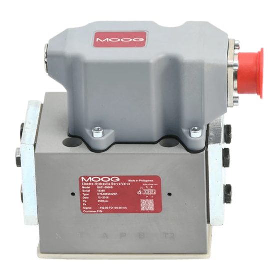
The Moog G631/631 Series Industrial Servovalve consists of a polarized
electrical torque motor and two stages of hydraulic power amplification. The
motor armature extends into the air gaps of the magnetic flux circuit and is
supported in this position by a flexure tube member.The flexure tube acts as a
seal between the electromagnetic and hydraulic sections of the valve.The two
motor coils surround the armature, one on each side of the flexure tube.
The flapper of the first stage hydraulic amplifier is rigidly attached to the
midpoint of the armature.The flapper extends through the flexure tube and
passes between two nozzles, creating two variable orifices between the nozzle
tips and the flapper.The pressure controlled by the flapper and nozzle variable
orifice is fed to the end areas of the second stage spool.
The second stage is a conventional 4-way spool design in which output
flow from the valve, at a fixed valve pressure drop, is proportional to spool
displacement from the null position.A cantilever feedback spring is fixed to the
flapper and engages a hole at the center of the spool. Displacement of the spool
deflects the feedback spring which creates a force on the armature/flapper
assembly.
Input signal induces a magnetic charge in the armature and causes a
deflection of the armature and flapper.This assembly pivots about the flexure
tube and increases the size of one nozzle orifice and decreases the size of the
other.
This action creates a differential pressure from one end of the spool to
the other and results in spool displacement. The spool displacement transmits a
force to the feedback wire which opposes the original input signal torque. Spool
movement continues until the feedback wire force equals the input signal force.
CAUTION
DISASSEMBLY, MAINTENANCE, OR REPAIR OTHER THAN IN ACCORDANCE WITH THE
INSTRUCTIONS HEREIN OR OTHER SPECIFIC WRITTEN DIRECTIONS FROM MOOG WILL
INVALIDATE MOOG'S OBLIGATIONS UNDER ITS WARRANTY.
G631/631 Series Installation and
Operation Instruction
Electrohydraulic Servovalve
ELECTROHYDRAULIC VALVE CUT-AWAY
Null Access
Screw
Null Adjust
Torque Motor
Coil
Armature
Flexure Tube
Filter
X
T
A
P
Figure 1 Moog Series G631/631
Upper Polepiece
Flapper
Nozzle
Feedback Wire
Spool
Inlet Orifice
Filter Plate
(not shown)
B
Advertisement

Related Manuals for Moog G631 Series


Summary of Contents for Moog G631 Series
- Page 1 2. OPERATION The Moog G631/631 Series Industrial Servovalve consists of a polarized electrical torque motor and two stages of hydraulic power amplification. The motor armature extends into the air gaps of the magnetic flux circuit and is supported in this position by a flexure tube member.The flexure tube acts as a...
- Page 2 Mechanical Null Adjustment 4. INSTALLATION Null Access The Moog G631/631 Series Servovalves may be mounted in any position, Screw provided the servovalve pressure, control and return ports match respective manifold ports.The mounting pattern and port location of servovalve are shown on Figure 4.
- Page 3 Reinstall in reverse order, torque screws to 38-40 in-lbs. 9. AUTHORIZED REPAIR FACILITIES Moog does not authorize any facilities other than Moog or Moog subsidiaries to repair its servovalves. It is recommended you contact Moog at (716)655-3000 to locate your closest Moog repair facility. Repair by an independent (unauthorized) repair house will result in voiding the Moog warranty and could lead to performance degradation or safety problems.
- Page 4 External X open closed Moog Inc., East Aurora, NY 14052-0018 Telephone: 716/652-2000 Fax: 716/687-7910 Toll Free: 1-800-272-MOOG www.moog.com/industrial The products described herein are subject to change at any time without notice, including, but not limited to, product features, specifications, and designs.
Need help?
Do you have a question about the G631 Series and is the answer not in the manual?
Questions and answers