Advertisement
Quick Links
OPERATING AND MAINTENANCE
CONTENTS
1.0.
2.0.
TECHNICAL DATA TABLE
3.0.
DEFINITION OF DIAPHRAGM PUMP
4.0.
5.0.
6.0.
INSTRUCTIONS AND MANUAL OF DIAPHRAGM PUMP
7.0.
10.0. PRECAUTIONS ON DISPOSING OF THE DIAPHRAGM PUMP
Attachment-1 Pump Performance Charts
Attachment-2 Gisan Warranty
Gisan Machinery Industry and Trade Co. Ltd.
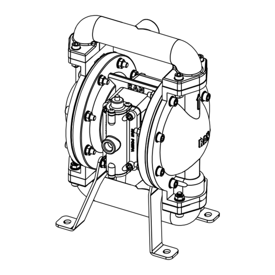
RAN 1/2" B15-AX MODEL
DIAPHRAGM PUMP
MANUAL
www.ranpump.com
Advertisement

Related Manuals for Ranpump B15-AX


Summary of Contents for Ranpump B15-AX
-
Page 1: Table Of Contents
RAN 1/2” B15-AX MODEL DIAPHRAGM PUMP OPERATING AND MAINTENANCE MANUAL CONTENTS 1.0. IMPORTANT SAFETY REQUIREMENTS 2.0. TECHNICAL DATA TABLE 3.0. DEFINITION OF DIAPHRAGM PUMP 4.0. HANDLING, MOVING, OPENING PACKAGE OF DIAPHRAGM PUMP 5.0. MOUNTING AND CONNECTING OF DIAPHRAGM PUMP 6.0. -
Page 2: Important Safety Requirements
1.0. IMPORTANT SAFETY REQUIREMENTS a- This equipment is for professional use only. Observe all warnings. Read and understand all instruction manuals, warning labels, and tags before you operate the equipment. b- CAUTION: This manual contains important instructions and safety cautions on diaphragm pumps. - Page 3 WARNING ! Always wear appropriate clothing and equipment, such as eye protection and breathing apparatus to protect yourself. WARNING ! Improper handling, splashing in the eyes, ingestion, or bodily contamination of hazardous fluids or inhaling toxic vapors can cause extremely serious injury or death. Observe all the following precautions when handling known or potentially hazardous fluids.
- Page 4 2.0. DIAPHRAGM PUMP TECHNICAL DATA 1/2 ’’ ALUMINIUM PUMP Description Unit Value 1/2” Aluminium Pump Type Inch Max. fluid working pressure Bar, Psi 7 (0.7 Mpa, 105 Psi) 1.0 to 7 Air feeding pressure range (0.10 - 0.7 Mpa, 105 Psi) Max.
- Page 5 RIGHT STROKE MIDDLE STROKE LEFT STROKE Compressed air is directed to When the pressurized At completion of the stroke, the back side of diaphragm B diaphragm, diaphragm B, the air valve again redirects by the air valve. The reaches the limit of its air to the back side of compressed air moves the discharge stroke, the air valve...
- Page 6 3.1.Diaphragm pump has the name plate shown on diagram 1 Figure 1- Pump Name Plate 3.2. Diaphragm pump coding system X X – X X Inlet Dıaphragm Body materıal materıal outlet B = 1/2” A = Aluminium 0 = Buna- N DIAPHRAGM C = 3/4”...
-
Page 7: Handling, Moving, Opening Package Of Diaphragm Pump
3.4. Diaphragm pump main dimensions. Figure 3 – Diaphragm pump main dimensions. 4.0. HANDLING, MOVING, OPENING THE PACKAGE OF DIAPHRAGM PUMP Handle the pump by manifolds to move. Pumps are packed in carton boxes. Figure 4 – Pump package. Pump package must be at least 130 grams and produced from the kraft carton. It must be fully covered with packaging separators. -
Page 8: Mounting And Connecting Of Diaphragm Pump
5.0. MOUNTING AND CONNECTION OF DIAPHRAGM PUMP A typical setup configuration is shown in figure 7. Further information and consultation on pump setup can be provided by your Ran Pump distributor. ALWAYS USE ORIGINAL RAN PUMP PARTS AND ACCESSORIES. FAILURE TO DO SO WILL INVALIDATE THE GUARANTEE Pump should fixed firmly to the ground or platform and should be fitted in a perpendicular position as shown in Figure 5. - Page 9 5.2. Tightening the bolts before first use After you unpack the pump, and before you use it for the first time, check and tighten external fasteners. Tighten the fluid cover screws first, then the manifold screws. (Refer to Figure 7for torque figures).
- Page 10 Figure 8a - Typical installation scheme 5.5. Fluıd lıne 5.5.1. Fluid suction line 1- Use a conductive hose or pipe. 2- Screw fluid fitting into the pump inlet tightly. 3- If the inlet fluid pressure is more than 25% of the outlet working pressure, ball check valves will not close fast enough, result will be inefficient pump operation.
- Page 11 Caution. It is advisable to install a pressure relief system (bypass line)to relieve high levels of pressure that may occur if the pump is pressurised for a long period when not operating. On some uncontrolled systems the back pressure generated from a closed outlet hose can cause the pump to stop or even reverse operation.
- Page 12 5.6 Ground the pump as shown below 5.6.1. For the pump: Use a conductor (for grounding) with a cross-section of at least 1.5 mm Connect the conductor to the pump’s leg as shown on Fig. 9, and the other end to the grounding line.
- Page 13 WARNING ! When you are transferring hazardous fluids or the pump temperature is over 60C, operator has to make precautions to drain the fluid. WARNING ! FIRE AND EXPLOSION HAZARD If you are working with flammable fluids, be sure to take precautions around the pump while cooling it.
- Page 14 6.0. PUMP OPERATION INSTRUCTIONS IMPORTANT NOTE The pump has a variable temperature resistance to the transferred fluid. The temperature resistance of the diaphragm, balls, and ball seats defines the temperature resistance of the pump. 6.1. Flush the pump before use. Pump is tested with water.
-
Page 15: Assembly And Dismantling Of Parts
7.0 ASSEMBLY AND DISMANTLING OF PARTS WARNING: Before service and maintenance always relieve the air and fluid pressure. This explanation refers to figures defined in part (7.0) line (12) fig. 14. 7.1. Ball check valve repair Tools required - Torque wrench - 5 mm allen key - 10 mm wrench 7.1.1 Dismantling... - Page 16 1- Relieve the pressure. 2- Remove the manifolds and disassemble the ball check valves as explained in Ball Check Valve Repair section. 3- Using a 5mm allen key remove the bolts connecting fluid chamber body sections from the centre section. Remove the fluid chamber body sections. 4- Using a13mm socket wrench on each side simultaneously loosen both the diaphragm bolts.
-
Page 17: Periodic Maintenance
Figure 13a - Removing the air valve 7-When replacing, repairing and installing the Pilot Valve please follow the correct procedure exactly as laid out.(See Figure 13b) Figure 13b - Pilot valve repair. 8.0 PERIODIC MAINTENANCE 8.1 Cleaning and storage of the pump Do not let your fluid dry in the pump or in the hoses. - Page 18 8.4. Weekly maıntenance 1- Apply the instructions for daily maintenance. 2- Clean the check valve balls and ball seats. 3- Clean the exhaust. 8.5. Monthly maıntenance 1- Check the valve balls diameter. Check the inner diameter of the ball seats. 2- Ball diameter must be bigger (at least 1.5 mm) than the inner diameter of the seat.
- Page 19 8.6 Troubleshooting NOTE: Before dismantling the pump please check for all possible problems. PROBLEM CAUSE SOLUTION 1- Pump cycles at Worn check valve balls, seats or o- stall or fails to hold Replace. rings. pressure at stall. Disassamble and clean air valve. Air valve is stuck or dirty.
-
Page 20: Storage Of Diaphragm Pump
Tel: 00 90 212 875 03 17 Fax: 00 90 212 875 03 18. Address: Birlik Sanayi sitesi 3. Cadde No: 83 Beylikdüzü Istanbul Turkey E-mail / Web : info@ranpump.com / www.ranpump.com CAUTION: PUMPS RETURNED TO GISAN FOR SERVICING. THE PUMP SHOULD BE THOROUGHLY CLEANED AND EMPTY AND PACKAGED SECURELY AND SAFELY TO PROTECT PEOPLE AND THE ENVIRONMENT. -
Page 21: Ordering Spare Parts
12.0 ORDERING SPARE PARTS No spare parts supplied with the diaphragm pump. Contact us using above method to order. No Code Parts No Code Parts B1012 Center section Valve fixing bolt B1111 Shaft O-ring B3311 Exhaust cover B1211 Shaft seat B3313 Exhaust B1311 Shaft cover... - Page 22 Figure 14b: Pump assembly scheme for RAN 1/2”.
- Page 23 ATTACHMENT-1 1/2" DIAPHRAGM PUMP PERFORMANCE CHARTS Reduce flow rate by 20% if there are Teflon diaphragms on your pump.
- Page 24 Gisan Makine San. Tic. Ltd. Şti. Birlik Sanayi Sitesi 3. Cadde No: 83 Beylikdüzü İstanbul Turkey Tel. : 00 90 212 875 03 17 (pbx) Fax: 00 90 212 875 03 18 E-mail / Web : info@ranpump.com / www.ranpump...
Need help?
Do you have a question about the B15-AX and is the answer not in the manual?
Questions and answers