Table of Contents
Advertisement
Quick Links
Advertisement
Table of Contents

Related Manuals for Plus M-18S


Summary of Contents for Plus M-18S
- Page 1 Copyboard M-18S/M-18W M-17S/M-17W SERVICE MANUAL 02.04.2012. Ver.1.0...
-
Page 2: Table Of Contents
CONTENTS 5. ADJUSTMENT............19 1. COMPLIANCE OF SAFE REPAIR ......3 5-1. Calibration............19 1-1. Cautions during Product Movement ....3 5-2. Changing the Internal Program of M-18/M-17 Main Set..20 1-2. Cautions during disassemblying and assembling ...3 5-3. Test mode............21 2. SPECIFICATIONS .............4 6. -
Page 3: Compliance Of Safe Repair
1. COMPLIANCE OF SAFE REPAIR Be sure to read this Service Manual before providing services. In the PLUS Copyboard, full consideration is taken to ensure the safety for a fire, electric shock, injury, harmful radiation, and substance. Therefore, observe the notice described in this Service Manual so that the safety is kept when providing services. -
Page 4: Specifications
2.SPECIFICATIONS 2-1. Product Specifications BOARD TYPE (Model name) Standard (M-18S) Wide (M-18W) Installation method Self-standing (T-shaped legs), or wall mounting External dimensions W1480 × D675 × H1947*² mm W1980 × D675 × H1947*² mm Form (T-shaped legs*¹) Main unit weight 20 kg*³... -
Page 5: Product Specifications M-17
SPECIFICATION 2-2. Product Specifications BOARD TYPE (Model name) Standard (M-17S) Wide (M-17W) Installation method Self-standing (T-shaped legs), or wall mounting External dimensions W1480 × D675 × H1947*² mm W1980 × D675 × H1947*² mm Form (T-shaped legs*¹) Main unit weight 15 kg*³... -
Page 6: Names Of The Parts
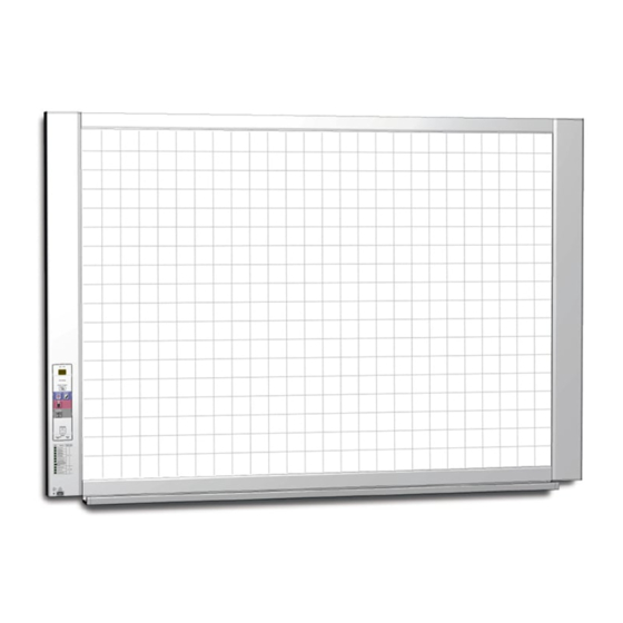
SPECIFICATION 2-3. Names of the Parts Front Main Unit Frame Cover Sheet Dedicated markers are used on the Sheet to draw diagrams and to write. Control Panel Input/output terminals Pen Tray (see next page) * Located on the bottom surface. Printer Table The printer* is placed here. - Page 7 SPECIFICATION Input/output terminals The connector is located on the bottom surface of the Main Unit. The diagram view is seen from the bottom. Please connect dedicated or recommended printer. PRINTER DC12V * This illustration does not show the printer or connection cords. Personal computer (PC) dedicated USB DC input connector port (Type B) Connect this with the DC plug end of the AC...
-
Page 8: Control Panel
SPECIFICATION 2-4. Control Panel When pressing a button, please press the center area (the square bulge). The button may not work if it is pressed on a corner. 1 ON/Standby button Turns the Copyboard’s power on and off (standby mode). 2 Display window The number of copies, operating status and error messages are displayed on the 7-segment LEDs. -
Page 9: Meaning Of Error Messages
Main Unit? device is disconnected, the power will Memory has been forgotten be switched off and the unit will enter the standby mode. If the problem persists, please contact your nearby PLUS Corporation sales office, dealer, or store. -
Page 10: Trouble Shooting
3.TROUBLE SHOOTING By checking operations, it is possible to carry out judgments on malfunction to a certain extent. Carry out the following checks before disassembling the equipment. 1. Press the Standby (On) button and turn on the power. Is the power turned on? No →... -
Page 11: Disassembly And Assembly
4.DISASSEMBLY AND ASSEMBLY 4-1. Tools Required • Phillips screwdriver (+) No. 2 • Phillips screwdriver (–) 4-2. Caution • See “1. Compliance of Safety Repair” before disassembling and assembling. • Put on gloves so that you do not cut your hand at the sharp edge of a frame during disassembly and assembly. •... -
Page 12: Disassembly And Assembly
DISASSEMBLY AND ASSEMBLY 4.4. Disassembly and Assembly This section describes one example of disassembly and assembly procedures. For the actual operation, disassemble and assemble the required parts with reference to “4-3. Disassembly and Assembly Procedures”. * Remove the main set from the stand and proceed with the Endless Sheet. (Perform the operation on a mat.) * Remove the Pen Tray before performing the procedure below. - Page 13 DISASSEMBLY AND ASSEMBLY 2) Remove the Frame Cap PC. (See Fig. 6.) 1.Remove the “S-2” screws shown in the figure 6 and then remove the Frame Cap PC. 2.Disconnect the connector connected to the USB Board shown in the figure 7. 3.Remove the “S-3”...
- Page 14 DISASSEMBLY AND ASSEMBLY 2. Remove the Panel Side R. 1 Remove the “S-4” screws shown in the figure 11 and then remove the Panel Side R. Panel Side R Fig.11 5) Remove the Back Panel Unit. (See Fig. 12.13) 1.Remove the “S-5” screws shown in the figure12. Remove two screws which are located on both sides of the Back Panel center.
- Page 15 DISASSEMBLY AND ASSEMBLY 3.Remove the “S-3” screws shown in the figure [When installed] 16 and then remove the SW Board. 1.Put the protrusion from the bottom of the SW Panel when Note: Pay attention to the wire drawing of the SW Cable returning the SW Panel to the former position.
- Page 16 DISASSEMBLY AND ASSEMBLY 8) Remove the Rear Frame. (See Fig. 22) 1.Remove the “S-6” screws shown in the figure 22 and then remove the Rear Frame (two). Rear Frame This side is located upwards. Fig.22 9) Remove the Panel Upper. (See Fig. 23) 1.Remove the “S-4”...
- Page 17 DISASSEMBLY AND ASSEMBLY 11) Replace the Endless sheet. 1.Remove the “S-2” screws shown in the figure 26. 2.Remove the Panel Plate shown in the figure 27. 3.Remove the stopper “S-4” screws in the (two upper and lower) Tension Roller Bases shown in the figure 28. 4.Push the Tension Roller Base block shown in the figure 29 into the inside and fix the Tension Roller Bases.
- Page 18 DISASSEMBLY AND ASSEMBLY 12) Replace the Sheet Motor Assy. (See Fig. 30) 1. Remove the “S-4” screws shown in the figure 30. 2. Disconnect the connector of the Sheet Motor Assy. Note: Be careful not to interfere with the Sheet Guide Bar when installing the Sheet Motor Assy.
-
Page 19: Adjustment
5. ADJUSTMENT 5-1. Calibration Calibration is required in the following cases. • When a Main Board is replaced • When a CIS Unit is replaced • When an Endless Sheet is replaced • When a Sheet Frame Unit is replacedFor the replacement of a CIS Unit in the market, usually, use a unit that has been adjusted at a factory. -
Page 20: Changing The Internal Program Of M-18/M-17 Main Set
ADJUSTMENT 5-2. Changing the Internal Program of M-18 Main Set [How to rewrite program using PC] Equipment used 1) Firmware data for M-18 / M-17 2) PC main set (OS: Windows XP/Windows Vista/Windows7) 3) USB Cable 1. Connect the PC and Copyboard main set using a Removable Disk(D) USB Cable. -
Page 21: Test Mode
ADJUSTMENT 5-3. Test mode 1. Program version display • Insert the plug of an AC Adaptor into the main set to apply the electric current (in the Standby state). • Press the Save button three times while pressing and holding the Power (ON / Standby) button. Test / adjustment mode segment display: <A.P>... -
Page 22: Device Setting
2. Open [My Computer], and from there open the copyboard identified as a removable device. For the Copyboard’s device (displayed as a removable disk), right-click [My Computer] to display the menu, then at [(Properties) -> [Device Manager], check that "PLUS Copyboard USB Device" is displayed as the disk drive name. Removable Disk(D) Properties... - Page 23 DEVICE SETTINGS 3. Open the "CBSetup" file in the "setup" folder. (1) Double-click the "setup" folder to open it. (2) Open the “CBSetup” file in the “setup” folder using your Web browser. Double-click the CBSetup file to open it. * Depending on the browser’s version, etc., the file may not open. * Follow the displayed instructions when security protection display appears.
- Page 24 DEVICE SETTINGS (2) If you have changed the Copyboard's device settings, click the "Set" button for the "Settings" section. (3) The save file screen appears when one of the "Set" buttons is pressed. Save the "setting.ini" file (overwriting the previous file) in the following location: Save to location: "setup"...
- Page 25 DEVICE SETTINGS [Way to rewrite the setting file directly] Rewriting the "setting.ini" settings file directly Depending on the browser’s version, etc., the file may not open. In this case, open the "setting.ini" file (in text format) using Notepad or another application on the computer and rewrite the contents of the settings file directly. Description example: Date=2011/02/03 ·················...
-
Page 26: Cable And Cable Connection
7. CABLE AND CABLE CONNECTION M-18 Unit : M-17 Unit CN1 CIS cable 22Pin FFC CN3 Switch cable 7pin red cable CN2 Motor cable 4pin blue cable CN6 USB Board cable 8pin gray cable Unit Main board Assy 100-240VAC AC adapter 12V / 3A Motor Printer USB Board USB Memory... -
Page 27: Parts List
8. PARTS LIST 1. PANEL SIDE... - Page 28 PARTS LIST 1. PANEL SIDE PARTS No. PARTS NAME Q' ty REMARK Panel Side L 726110100 Panel Side R 726110200 Frame Cap PC 726120400 Frame Cap B 726120600 Frame Cap A 726120500 USB Board Assy 726580200 Tray Unit S 302009 Tray Unit W 302010 SW Board M-17/18...
-
Page 29: Main Board Cis Unit Cable
PARTS LIST 2. MAIN BOARD. CIS UNIT. CABLE... - Page 30 PARTS LIST 2. MAIN BOARD. CIS UNIT. CABLE PARTS NAME PARTS No. Q' ty REMARK CIS Unit 302008 Main Board Shield 726135500 M-18 Only Main Board M-18 726581400 M-17 Only Main Board M-17 726581407 Main Board Sheet 726951100 Cable Cover 726123100 CIS Cable 726590200...
-
Page 31: Sheet Frame
PARTS LIST 3. SHEET FRAME... - Page 32 PARTS LIST 3. SHEET FRAME PARTS No. PARTS NAME Q' ty REMARK Panel Plate A 726130100 Panel Plate B 726130200 Rear Frame 726310100 Back Panel Unit S 302001 Back Panel Unit W 302002 Endless Sheet S M-17/18/N-20 302005 Endless Sheet W M-17/18/N-20 302006 Upper-Lower common Panel Front S M-17/18...
-
Page 33: Accessories
PARTS LIST 4. ACCESSORIES M-18S/W) M-17S/W) USA Only (M-18S ・ W) - Page 34 PARTS LIST 4. ACCESSORIES PARTS NAME PARTS No. Q' ty REMARK Eraser 51-058 51058 NO Parts Supply Marker Set Marker Set for M-17 NO Parts Supply Manual CD-ROM M-18 M-18 Only 726461500 M-17 Only Manual CD-ROM M-17 726461300 Assembly Manual M-17/18 (O/S) 726460300 Safety Guide 726460800...
-
Page 35: Carton
PARTS LIST 5. CARTON USA Only (M-18S ・ W) W type... - Page 36 PARTS LIST 5. CARTON PARTS No. PARTS NAME Q' ty REMARK Carton Unit S M-17/18/N-20/C-20 302011 Carton Unit W M-17/18/N-20/C-20 302012 Carton S Upper NO Parts supply Carton W Upper NO Parts supply Carton S Lower NO Parts supply Carton W Lower NO Parts supply Packing A NO Parts supply...
-
Page 37: M-18/N-20-T
PARTS LIST 6. M-18/M-17/N-20-T T-11 T-15 T-15 T-13 T-15 T-14 T-12 T-16 T-10 S-14 S-10 S-11 S-13 S-12 S-11 S-12 S-13 S-11 T-18 T-19 T-20 T-17 S-12 T-21 S-11 T-22 T-25 S-12 T-24 T-23 T-22... - Page 38 PARTS LIST 6. M-18/M-17/N-20-T PARTS No. PARTS NAME Q' ty REMARK No Parts Supply T Stand (O/S) Side Bar 726332000 Printer Table (Stand Type) 726135900 Edge Holder 723191100 Adapter Holder 726136100 Stand Cap Upper 726321200 Stand Cap Lower 726321100 Front Caster 714660400 Back Caster 714660500...
-
Page 39: Screws & Washers
PARTS LIST 7. SCREWS & WASHERS PARTS No. PARTS NAME Q' ty REMARK M3-6 Cross Recessed Pan Head Double Sems 952530610 M4-8 Cross Recessed Low Head 961540810 M3-8 P-tight Cross Recessed Bind Head 963230810 M4-12 Cross Recessed Low Head 963941210 M4-40 B-tight Cross Recessed Bind Head 963444010 M4-10 Cross Recessed Pan Head Sems... - Page 40 PLUS Corporation Stationery Company...
Need help?
Do you have a question about the M-18S and is the answer not in the manual?
Questions and answers