Table of Contents
Advertisement
Quick Links
Advertisement
Table of Contents

Related Manuals for Plus M-18S


Summary of Contents for Plus M-18S
- Page 1 M - 18S/M - 18W User’s Manual Thank you for your purchase of the PLUS Copyboard. Please read this User’s Manual carefully before use to take full advan- tage of the functions of this product. After you have finished reading...
-
Page 2: Introduction
Introduction This manual is for both the M-18S and M-18W models. The copyboards come in two sizes: standard size (model M-18S) and wide size (model M-18W). The descriptions and diagrams in this manual refer to the model M-18S. * When functions or operations are specific to a certain model of copyboard, the model name is specified. -
Page 3: Table Of Contents
Table of Contents Introduction .................... E-2 Package Contents .................. E-4 Names of the Parts ................... E-5 Front ....................... E-5 Input/output terminals ................ E-6 Changing the Height of the Unit .............. E-7 Control Panel .................. E-8 Operation Steps .................. E-9 Connecting the Power ................ E-10 Printing (printer sold separately) ............ E-11 Preparing the Printer ................ E-11 Basic Printing Operation ............... -
Page 4: Package Contents
Assembly and installation parts Main unit fixing screws (M4 × 12: 2) Pen tray [1] * Sold separately for some products. Pen tray fixing screws (M4 × 20) (temporarily fastened on main unit) Wall mount printer table [1 set] M-18S: 3 screws, M-18W: 4 screws Bracket fixing screws (M4 × 8): 4 (See the Assembly and Setup Manual for assembly instruc- AC power adapter box: 1 tions.) Velcro: 2 sets * Sold separately. -
Page 5: Names Of The Parts
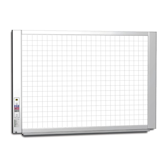
Names of the Parts Front Main unit Frame cover Sheet Dedicated markers are used on the sheet to draw diagrams and to write. Control panel (See Page E-8) Pen tray Input/output terminals (see next page) * Located on the bottom surface. Printer table The printer* is placed here. (See the Assembly and Setup Manual.) * The printer is sold separately. -
Page 6: Input/Output Terminals
Names of the Parts Input/output terminals The connector is located on the bottom sur- face of the main unit. The diagram view is seen from the bottom. * This illustration does not show the printer or connection cords. DC input connector Connect this with the DC plug end of the AC power Personal computer (PC) dedicated USB adapter. (See Page E-10.) (Only connect the supplied port (Type B) AC power adapter; nothing else.) Connect this with the USB port (type A) of the PC. Used to connect the copyboard to a computer to make the copyboard’s device settings. Can also be used to copy scanned images onto the computer. -
Page 7: Changing The Height Of The Unit
Names of the Parts Changing the Height of the Unit This is the height adjustment when setting up the copyboard on the optional stand. The stand height can be adjusted to 3 levels by 100 mm. CAUTION • At least two persons should hold the main unit. If not, the main unit could drop or tip, resulting in accidental injury. • Lock the stand’s casters by pressing the bottom of the caster lock button. If not, the stand could move while the main unit is being mounted or removed, resulting in accidental injury. -
Page 8: Control Panel
Names of the Parts Control Panel When pressing a button, please press the center area (the square bulge). The button may not work if it is pressed on a corner. ON/Standby ( ) button Turns the copyboard’s power on and off (standby mode). Display window The number of copies, operating status and error mes- sages are displayed on the 7-segment LEDs. -
Page 9: Operation Steps
Operation Steps The copyboard uses a CIS (Contact Image Sensor) image sensor to read the diagrams and text that have been written down with special (4-color) markers, and accumulates the image data in internal memory. The sheet surface’s image data is printed out from the printer when the Color Print ( ) or B/W Print ( ) button is pressed, or stored as image data on the USB memory device or in the main unit’s internal memory when the... -
Page 10: Connecting The Power
Connecting the Power Note About the connection and the AC adapter box Place the AC power adapters of the main unit and printer in the AC adapter box. If you only have one power outlet, connect the AC power adapters of the main unit and printer to a commercially available cable tap, place them in the AC adapter box, and connect the cable tap’s power plug to the wall power outlet. Also, if not connected or placed in the AC adapter box, see the separate “Assembly and Setup Manual” and connect accord- ing to the purpose. Wall outlet Printer’s AC power adapter AC adaptor box Copyboard’s AC power adapter * Be sure to insert all the plugs securely. To use the copyboard, connect the copyboard’s AC power plug to a wall power outlet. The main power turns on. In this manual, this is referred to as the “standby mode”. The descriptions in this manual assume that the AC power plug is connected (that the unit is in the standby mode). About the printer’s power supply • When using a printer, connect its power plug to a wall power outlet. Also, turn on the printer’s power before printing. -
Page 11: Printing (Printer Sold Separately
Printing (printer sold separately) Use a printer to print out the image that has been drawn on the sheet surface. Use a PLUS-designated printer. Operations and names of parts differ from printer to printer. For details of operations, see your printer’s operat- ing instructions. -
Page 12: Basic Printing Operation
Printing Basic Printing Operation Preparation: Preparation: Check that the AC power plugs of the copyboard and printer are connected to wall power outlets. See Page E-10. Press the ON/Standby button and switch on the power. Prepare the printer. (See the previous page.) Note • When turning on the power, wait about 5 seconds after connecting the copyboard’s AC power plug to the wall power outlet or after turning off the power (standby mode) before pressing the ON/Standby button. • Press the ON/Standby button to switch on the power. The LED of the display window will light. • Turn on the copyboard’s power before turning on the printer’s power. Press the Scroll/Stop button and display the sheet sur- face you want to print. -
Page 13: Moving The Sheet Surface Manually
Printing Press the Color Print or the B/W Print button to print. • The reading operation is performed for a one-sheet portion (while the sheet is scrolled) and the printing operation is performed. Cancellation of the print operation in progress When the ON/Standby button is pressed, the reading of the sheet stops, and the partially read image data is printed. Wait until the sheet is expelled from the printer. Note • If the ON/Standby button is pressed while the sheet surface is being read, printing is interrupted and only part of the image will be printed. To move the sheet surface, wait until scrolling stops, then press the Scroll/Stop button . • The one-screen portion is reduced to A4 paper size and printed. For wide type copyboards (model M-18W), the image is compressed about 75% in the horizontal direction. To print with the same proportions as the image on the sheet surface, see “Making the Device Settings” (page E-22). -
Page 14: Using Usb Memory
3-digit number starting from 001 (ex.: PV-001.pdf). Notice • No USB flash memory device is included. When purchasing a USB flash memory device, pay attention to the following: 1. USB flash memory devices formatted in FAT16/FAT32 are supported. USB flash memory devices in NTFS/exFAT format cannot be used. 2. USB flash memory devices protected by a security function cannot be used. 3. USB flash memory devices with a capacity of over 32 GB cannot be used. 4. If the USB flash memory device is divided into multiple partitions, only one partition can be recognized with this unit. • See the PLUS website for more information on USB memory devices usable with this unit. USB Memory Storage Procedure Preparation: Check that the copyboard’s AC power plug is connected to a wall power outlet. See page E-10. Press the ON/Standby button and switch on the power. Note • When turning on the power, wait about 5 seconds after connecting the copyboard’s AC power plug to the wall power outlet or after turning off the... - Page 15 Using USB Memory Press the Scroll/Stop button and display the sheet surface you want to store. The procedure for displaying the sheet surface you want to store is the same as for printing. See “Basic Printing Operation” on page E-12. Note • The one screen portion that is viewable will be saved in USB memory. • Saving of the portion located around the sheet surface might not be possible. Please see “Effective reading size” on Page E-5. Press the Save button to store. Flashing indicator “rotates” sequentially during USB memory storage operation. Display window • The reading operation is performed for a one-sheet portion (while the sheet is scrolled) and USB memory storage starts after the scrolling completes.
- Page 16 Using USB Memory When the copyboard is not going to be used, press the ON/Standby button and switch off the power (standby mode). Note • “ ” letters appearing at one-second intervals in a moving display in the display window indicate that a USB memory device is mounted. Unplugging the USB memory device will switch off the power. (A function that serves as a reminder to unplug the USB memory device) • When the copyboard and a computer are connected by USB cable, the auto power off function (which turns the power off automatically) is canceled. • Scanned images files stored in the copyboard’s internal memory are cleared when the power is turned off (set to standby) with the ON/Standby button or when the computer is disconnected. E-16...
-
Page 17: Using The Copyboard Connected To A Computer
Using the copyboard connected to a computer When the copyboard and a computer are connected by USB cable, the copyboard is recognized as an exter- nal memory device (removable device). Below is the procedure for copying the “CBImage” file from this device onto the computer. -
Page 18: Cb Setup Procedure
CB Setup Procedure There are two ways to make the device settings: using the copyboard’s operation buttons to make the settings (“CB Setup”), making the settings using a USB connection. CB Setup (operating the copyboard’s buttons) Basic setting operation • Check that the power is on (that the display window is lit). •... -
Page 19: Table Of Function Numbers And Settings
CB Setup Procedure Table of Function Numbers and Settings Function Setting Item Description Setting Status Indicators Number The date and time are stamped on the printing paper Year, month, Not lit Time Setting and recorded in the file information when files are day, hours, stored. (See Page E-20) minutes Selection of whether to print in A4 paper size or letter Copyboard Device size. (Lit) (Off) Paper Size • This operates when the copyboard is connected to Letter Copyboard Device... -
Page 20: Cb Setup Procedure (Setting The Time
CB Setup Procedure (Setting the Time) The date and time are stamped on the printing paper and recorded in the file information when files are stored on the copyboard, so set the copyboard’s time correctly. Description of Operations Switch to “CB Setup”. With the power turned on, press the Number of Copies but- ton while pressing the ON/Standby button, then release the... - Page 21 CB Setup Procedure (Setting the Time) Press the Save button to move to the last dig- its of the year The display switches to “c2” (last 2 digits of year). Notice: The first two digits of the year (“20”) are fixed. Simply press the Save button to switch to the last 2 digits of the year setting position. Use the Color Print (Increase) and B/W Print (Decrease) buttons to select “20” (the last 2 digits of the year), then press the Save button to enter.
-
Page 22: Making The Device Settings
Making the Device Settings Make the copyboard’s device settings (paper size, aspect ratio setting, graphics file format and time setting) using a computer. When the copyboard and a computer are connected, the copyboard is recognized as an external memory device (removable device). Notice • Do not save data from a computer into the copyboard’s internal memory. • The copyboard’s internal memory cannot be formatted from a computer. • Do not disconnect the USB cable or access the copyboard while the data is being saved after pressing the copyboard’s Save ( ) button/. Doing so may cause operation of the computer to become unstable. • Do not press any operation buttons on the main unit while the copyboard’s internal memory is being accessed from the computer. The response time could be long and the operation may not be possible. Turn on the copyboard’s power and connect the PC dedicated USB port (type B) and com- puter using the USB cable. - Page 23 Making the Device Settings Make the device settings and save the “setting.ini” settings file, overwriting the previous file. Description example: Item Date Date=2011/02/03 ......Time Time=00:00 ........Paper size A4Page=0 ........Stretch=1 ......... Printing Image Color Printing=0 ....... Color Printing Graphic File Format=2 ..... Image file format Item Item Name Setting Value (numbers to be input) Restrictions Date Date Current date Use “/” to separate the year, month and day.
-
Page 24: Meaning Of Error Messages
• Did you press the ON/Standby button • A USB memory device is plugged into is flowing...Warning that dis- while the USB memory device was plugged the main unit. When the USB memory connection of USB memory into the main unit? device is disconnected, the power will has been forgotten be switched off and the unit will enter the standby mode. If the problem persists, please contact your nearby PLUS Corporation sales office, dealer, or store. E-24... -
Page 25: Troubleshooting
When the copyboard and PC are con- • Check whether the copyboard is in an operable condition, and whether the nected, the PC does not recognize the USB cable is connected properly. copyboard • Is the copyboard connected to the PC via a USB hub? (Connect the copyboard directly to the USB port of the PC.) The date is not updated. • The copyboard’s battery is dead. Contact your store of purchase. * If the problem persists, please contact your nearby PLUS Corporation sales office, dealer, or store. Condition Please Check The copyboard’s power turns on, but the • Check whether the printer’s power plug (DC plug) is securely inserted. printer’s power does not. If the power still does not turn on, disconnect the AC adapter box and check whether the printer’s AC power adapter side plug is unplugged from the AC power adapter. (For some printers it is directly mounted.) A press of the Print button does not result • Check that the power cable of the printer and the printer cable are securely... - Page 26 Troubleshooting Test Printing 1) With the copyboard’s power on (with the display window lit), press the Number of Copies button repeatedly to display “ ” on the display window. 2) Press the Color Print ( ) button for a color print, the B/W Print ( ) button for a black-and-white print. * Test printing starts. Check the print • Is the each color line printed uniformly? • Are there missing dots, pale lines, lines with thinner ink than others, etc.? Remedy • If the nozzle is partially choked, clean it. • If the quality of the print does not improve even though the nozzle has been cleaned, wipe off the ink on the surface of te nozzle. For details, see the “User’s Guide” included with the printer. * Please see your printer manual for information about printing problems, printer maintenance, and details related to printing. E-26...
-
Page 27: Scanning Adjustment (White Calibration
Scanning Adjustment (White Calibration) If dark lines (horizontal black lines) on a printed out hard copy or image on the screen are generated, you need to optimally adjust the sensitivity of reading the sheet surface. If the scanning image does not work due to generation of dark lines, update the program and perform the white calibration in the following steps. -
Page 28: Specifications
Specifications BOARD TYPE (Model name) Standard (M-18S) Wide (M-18W) Installation method Self-standing with stand, or wall mounting External dimensions (T-shaped W1480 × D675 × H1947*² mm W1980 × D675 × H1947*² mm legs*¹) Form Main unit weight 20 kg*³ 25 kg*³... -
Page 29: Appendix
Appendix Connections and Wiring Diagram • The connections and wiring diagram below is included here for checking the connections. [Copyboard and Printer Connections Diagram] Copyboard front panel To Printer connector To DC INPUT connector USB cable (supplied with the printer) To USB connector Printer To DC connector Printer AC power adapter AC power adapter (supplied) (supplied with the printer) To wall power outlet * Appearance of printer is for illustration purposes. Note • The AC power adapters of accessories and printers that have been verified to be operation many differ from the ones shown on the connections diagram (they may be of the built-in or mounted-on type). - Page 30 ©2011 PLUS Corporation 26-4601-11D...
Need help?
Do you have a question about the M-18S and is the answer not in the manual?
Questions and answers