Advertisement
Quick Links
Owner's Guide and Installation Manual
Attach sales receipt to this card and retain as your proof of purchase
DATE OF PURCHASE:
MODEL NUMBER:
To register your fixture, please visit our website www.montecarlofans.com
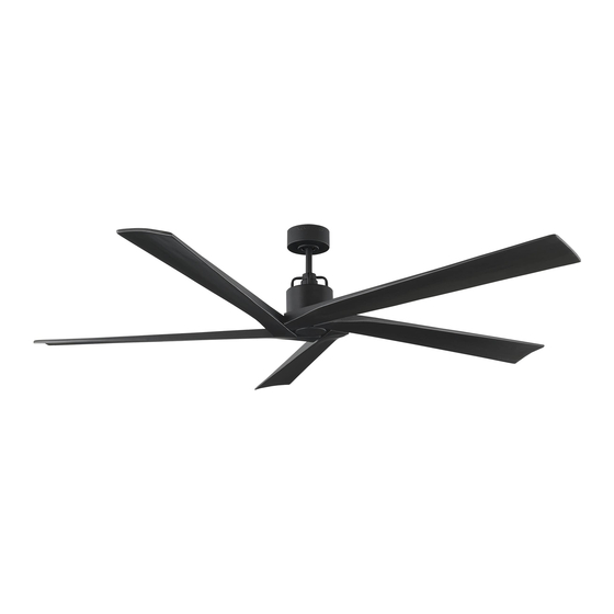
5ASPR70XXX Series Fan
cETL Model NO. : 5ASPR70
RETAILER NAME:
RETAILER ADDRESS:
7.34 kg
16.15 lbs
Total fan weight
Advertisement

Related Manuals for Monte Carlo Fan Company 5ASPR70 Series


Summary of Contents for Monte Carlo Fan Company 5ASPR70 Series
- Page 1 Owner’s Guide and Installation Manual 5ASPR70XXX Series Fan cETL Model NO. : 5ASPR70 Attach sales receipt to this card and retain as your proof of purchase DATE OF PURCHASE: RETAILER NAME: RETAILER ADDRESS: MODEL NUMBER: To register your fixture, please visit our website www.montecarlofans.com 7.34 kg 16.15 lbs Total fan weight...
-
Page 2: Cautions And Warnings
Cautions and Warnings WARNING: TO REDUCE THE RISK OF FIRE, ELECTRIC SHOCK, OR INJURY TO PERSONS, OBSERVE THE FOLLOWING READ AND SAVE THESE INSTRUCTIONS Installation work and electrical wiring must be done by qualified person(s) in accordance with applicable codes and standards (ANSI/NFPA 70), including fire-rated construction. - Page 3 Mounting bracket Before you begin installing the fan, Switch Before installing this fan make sure the Use metal outlet box suitable for fan power off at Service panel and lock outlet box is properly installed to the support and use only the screws provided service disconnecting means to prevent house structure.
- Page 4 Keeper pin Cross pin Thread lead wires and safety cable from For easy assembling of the Slip downrod into motor housing yoke, Helpful hint: aligning holes and install cross pin and keeper motor assembly through downrod. cross pin on the next installation step. pin.
- Page 5 Wall Switch Black (Live) Power source White (Neutral) Blue (For Light) Ground/Green White (For Light) Red (Motor 1) Purple (Motor 2) Gray (Motor 3) Green/Ground Receiver Black (AC IN L) White (AC IN N) Partially loosen one and remove one Make wiring connections using wire connectors provided as indicated above.
-
Page 6: Remote Control Setting And Operation
REMOTE CONTROL SETTING and OPERATION Transmitter Operation Remove the battery cover from the remote control transmitter and install battery, battery provided. Replace the cover. Note: Use 2 1.5V/AAA battery. Note: If not using for long period of time, remove battery to prevent damage to remote transmitter, and store the remote transmitter away from excess heat or humidity. - Page 7 The buttons on the remote control transmitter control the fan speed and light as follows. Fan speed 1 = minimum speed 2 = low speed 3 = medium low speed 4 = medium speed 5 = medium high speed 6 = high speed This button turns the fan off.
-
Page 8: Troubleshooting
Trouble Shooting or wiring. In some cases, these installation errors may be mistaken for defects. If you experience any faults, installation, please call our Customer Service Center at the number printed on your parts list insert sheet. Warning means to prevent power from being switched on accidentally. When the service disconnecting means cannot be locked, securely fasten a prominent warning device, such as a tag, to the service panel. - Page 9 Jan.2021...
Need help?
Do you have a question about the 5ASPR70 Series and is the answer not in the manual?
Questions and answers