Table of Contents
Advertisement
Quick Links
Advertisement
Table of Contents

Subscribe to Our Youtube Channel
Related Manuals for Direct IP DC-E Series


Summary of Contents for Direct IP DC-E Series
- Page 1 DC-E Series Installation Manual DC-E4213WRX Powered by...
- Page 2 Before reading this manual This is a basic installation manual for use of an IDIS network camera. Users who are using this product for the first time, as well as users with experience using comparable products, must read this operation manual carefully before use and heed to the warnings and precautions contained herein while using the product.
- Page 3 Safety Precautions WARNING RISK OF ELECTRIC SHOCK DO NOT OPEN WARNING: TO REDUCE THE RISK OF ELECTRIC SHOCK, DO NOT REMOVE COVER (OR BACK). NO USER-SERVICEABLE PARTS INSIDE. REFER SERVICING TO QUALIFIED SERVICE PERSONNEL. Important Safeguards 1. Read Instructions 9. Overloading All the safety and operating instructions should be read before the Do not overload wall outlets and extension cords as this can result in appliance is operated.
- Page 4 Warning: This product emits infrared light. Do not look into the IR LED. FCC Compliance Statement THIS EQUIPMENT HAS BEEN TESTED AND FOUND TO COMPLY WITH THE LIMITS FOR A CLASS A DIGITAL DEVICE, PURSUANT TO PART 15 OF THE FCC RULES. THESE LIMITS ARE DESIGNED TO PROVIDE REASONABLE PROTECTION AGAINST HARMFUL INTERFERENCE WHEN THE EQUIPMENT IS OPERATED IN A COMMERCIAL ENVIRONMENT.
-
Page 5: Table Of Contents
Table of Contents Part 1 – Introduction ......... 6 Product Features . -
Page 6: Part 1 - Introduction
Part 1 – Introduction Product Features • IP filtering, HTTPS, SSL, IEEE 802.1X, and configurable user authority levels for greater security • Network bandwidth limitation and MAT features for DC-E4213WRX is an IP-based network camera that more efficient use of network bandwidth compresses and transmits video over ethernet. -
Page 7: Accessories
Part 1 – Introduction Accessories Upon purchasing the product, check inside the box to make sure all the following accessories are included. External appearances and colors of the accessories may vary depending on the model. RJ45 moduler jack, RJ45 waterproof rubber ring, RJ45 Network Camera connector protect cover, cable waterproof rubber ring, RJ45 connector back cover... -
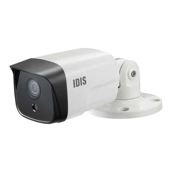
Page 8: Overview
Part 1 – Introduction Overview Product color and design may vary depending on the model. Body • Lens Fixed lens is installed. • IR LED A sensor in the bottom middle monitors lighting levels and activates the IR LED during low-lighting conditions. -
Page 9: Cable
Part 1 – Introduction Cable • Alarm in Connect an alarm-in device to this port. Connect a mechanical or electrical switch to the IN and GND (ground) connectors. Alarm in range is 0V to 5V. In order to detect alarm input from an electrical switch, the signal must be higher than 4.3V from an NC switch or less than 0.3V from an NO switch and must last for longer than 0.5 seconds. -
Page 10: Inserting A Sd Memory Card
Part 1 – Introduction Inserting a SD Memory Card Make sure that the cover is joined properly when screwing it; otherwise, the IP67 level is not guaranteed. Loosen the screws counterclockwise and remove the cover. Waterproof Cable Installation RJ45 waterproof rubber ring RJ45 modular jack RJ45 waterproof rubber ring RJ45 modular jack... -
Page 11: Installation
Part 1 – Introduction Not pulling the cable back may cause water to seep in and damage the product. Installation • Check the wall or ceiling to see if it needs to be reinforced. The camera may fall off if the wall or ceiling is not strong enough to support its weight. -
Page 12: Dimensions
Part 1 – Introduction Connect external devices, network and power f=4.0mm, 6.0mm adapter. 197mm Apply power. Dimensions f=2.8mm 195.8mm 17mm 85.8mm 80mm 31.2mm 75mm 17mm 85.8mm 80mm 30mm... -
Page 13: Part 2 - Camera Connection
Part 2 - Camera Connection Use the camera by connecting to DirectIP™ NVR or non DirectIP™ NVR, VMS such as IDIS Solution Suite Compact. With DirectIP™ NVR-based Layout Audio In Audio Out Sensor In Power Alarm Out Network Camera Monitor Out Power Network Remote Monitoring... -
Page 14: With Non Directip™ Nvr-Based Layout
Part 2 - Camera Connection With non DirectIP™ NVR-based Layout Sensor In Alarm Out Audio In Network Camera Audio Out microSD Memory Card Network Remote Monitoring Remote Recording (IDIS Solution Suite (IDIS Solution Suite Compact or IDIS Web) Compact) Control the camera over the network from software installed on a computer. Ideal for using the camera over the network from a remote location. -
Page 15: Part 3 - Appendix
Part 3 - Appendix Troubleshooting Problem Check The main unit won't turn • Check the power cable connection. • Check the power outlet. PoE switch isn't being Check the grounding status of the I/O device connected to the camera and the PoE recognized. -
Page 16: Specifications
Part 3 - Appendix Specifications These product specifications may change without prior notice. Video Image Sensor 1/2.8" CMOS Max. Resolution 1920 x 1080 Scanning Mode Progressive Scan Lens type Fixed-focal Focal Length f=2.8mm / f=4.0mm / f=6.0mm Aperture F2.0 / F2.15 / F1.6 Angular Field of View 134.45°(D) 113.74°... - Page 17 Part 3 - Appendix Network Video Compression H.265, H.264(MP), M-JPEG Bitrate Control CBR / VBR Max. Frame Rate 30fps : 1920 x 1080(WDR) Audio Compression ADPCM 16K, G.726, G.711 u-Law, G.711 a-Law Supported Resolution 1920x1080, 1280x720, 704x480, 640x360, 352x240 Multi-Video Streaming Quadruple Ethernet RJ45(10/100BASE-T)
- Page 18 IDIS Co., Ltd. For more information, please visit at www.idisglobal.com...
Need help?
Do you have a question about the DC-E Series and is the answer not in the manual?
Questions and answers