Table of Contents
Advertisement
Quick Links
140° F - Max Water Temp
1-1/2" - Suction
1" - Outlet
AR80BP - 550
m
odeL
AR80BP-C
AR80BP-SP
AR80BP-GR3/4-GCI
GCI - Pump with a mounted control unit.
d
K
iAPHRAgm
iTS
m
d
odeL
eScRiPTion
AR43247
BlueFlex
AR43245
Desmopan
AR43244
NBR
AR43246
Viton
INSTRUCTION MANUAL
- S
-H
RPm
emi
ydRAuLic
m
gPm
m
L/m
Ax
Ax
20.2
76.4
20.2
76.4
20.2
76.4
V
K
ALVe
iTS
m
d
odeL
eScRiPTion
AR42805
Valves
AR 80 bp
T
-d
HRee
iAPHRAgm
m
PSi
m
in
Ax
Ax
290
20
290
20
290
20
o-R
K
ing
iTS
m
d
odeL
eScRiPTion
AR42857
O-Rings
P
umP
B
HP P
AR
oweR
3.4
3.4
3.4
o
iL
d
m
odeL
AR64532D
Oil
AR64532D-C Case (6)Oil
w
eigHT
L
.
BS
30.9
30.9
40.0
eScRiPTion
Advertisement
Table of Contents

Related Manuals for Annovi Reverberi AR 80 bp Series


Summary of Contents for Annovi Reverberi AR 80 bp Series
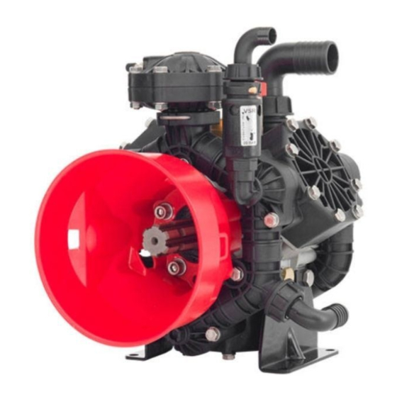
- Page 1 AR 80 bp 140° F - Max Water Temp 1-1/2” - Suction 1” - Outlet INSTRUCTION MANUAL AR80BP - 550 ydRAuLic HRee iAPHRAgm eigHT HP P odeL oweR AR80BP-C 20.2 76.4 30.9 AR80BP-SP 20.2 76.4 30.9 AR80BP-GR3/4-GCI 20.2 76.4 40.0 GCI - Pump with a mounted control unit.
- Page 2 Application Kits Low Pressure AR31058 AR43329 Shaft Kit AR43392: 1 3/8” Male Spline Shaft Pulley Kit AR31058 Pulley 2A 11” Diameter 1" ³⁄₈ universal shaft For AR45, AR80 86,5 For Models: AR70, AR115 & AR135 Hydraulic Motor Flange Kit AR55371 AR55371 AR1514 $281.40...
-
Page 3: Important Safety Information
IMPORTANT SAFETY INFORMATION Intended uses The pump is designed and constructed for incorporation in plants and machinery (spraying machines for the protective treatment of agricultural crops and garden plants). All other uses constitute misuse unless ap- proved by the manufacturer's technical service The pump must be used in a manner appropriate to its technical data (see “Technical Data”), and must not be modified or improperly used. - Page 4 Installation diagram (guideline) The following is a simplified illustration of the typical installation layout and is purely a guideline. Control Unit by-pass Tank Agitation Control Unit Intake filter Pump Delivery line filter...
-
Page 5: Installation Instructions
INSTALLATION INSTRUCTIONS General guidelines on water supply connection To operate correctly, the diaphragm pump must draw in liquids from containers at atmospheric pressure. Do not supply the pump with pressurised liquids. For continuous duty, the pump should not draw in water by gravity from containers with liquid level at heights above 3 m. - Page 6 Safety recommendations for handling and lifting Before starting the operations, organise the intended working area so that the materials can be lifted and handled in safety. Unloading, loading, handling and lifting operations must be carried out by skilled, authorised, specifi cally trained staff.
-
Page 7: Installation
Installation • The crankshaft may turn in either direction. • The water connection with the pump must be made using hoses of suitable diameter, in all case no less than that of the pump fittings, securing them to the fittings using good quality clamps. The intake hose must be coil-reinforced to prevent restrictions. -
Page 8: Preliminary Checks
Safety recommendations for use Before start-up, the operator must perform the necessary safety checks. In the event of leaks from the pressurized pipes, stop the pump at once and fix the leak. Do not operate the pump above the limits set by the manufacturer to increase its performance. Preliminary checks If the pump has a pressure accumulator, check its level of inflation, see "Checking the inflation pressure". - Page 9 Safety recommendations for maintenance Before doing any maintenance work, depressurise the water system and isolate the pump from all en- ergy sources. When the jobs are done, before restarting the pump, check that no tools, rags or other materials have been left close to moving parts or in hazardous zones.
- Page 10 Table of lubricants The pump is delivered complete with high-performance 30 weight, non-detergent oil suitable for the intended ambient conditions (see "Environmental operating limits"). Inspecting the pump mounting Check that the pump's fixing screws have not become loose. If necessary, tighten them with the driving torque stated in the installation design. Inspecting the connections and pipes - Inspect the connections for leaks.
-
Page 11: Pump Storage
Pump Storage It is important to comply with the recommendations for storage in the operator's manual of the machine into which the pump is incorporated. For the pump itself, at the end of pumping operations it is essential to flush out the pump by pumping clean water. -
Page 12: Troubleshooting
TROUBLESHOOTING The information provided is intended to provide guidance how to deal with malfunctions which may occur during use. Some of these procedures may be carried out by skilled staff, while others have to be performed at specialised service centres since they require the use of specific equipment as well as detailed knowledge of repair opera tions. - Page 13 TROUBLESHOOTING Remedy Problem Cause Oil seal on pump Replace the worn oil seal. shaft worn. Oil on pump body or base. Oil pressure inside pump too high. Restore correct oil level in tank. Pump using too much oil (oil flowing from delivery port) or oil Stop the pump at once.
- Page 14 A . . R R . . NOR T T H H A A M M E E R R I I C C A A AR 60bp GR-GCI / AR 80bp GR-GCI Warning! Fit with molybdenum disul de grease between plate and diaphragm.
- Page 15 AR 60bp GR-GCI / AR 80bp GR-GCI Code Description Note Code Description Note 1880240 Pin 3240031 Manifold 3/8" G 660171 O-ring Ø 31.42x2.62 390292 O-ring Ø 28.25x2.62 Viton 394211 O-ring Ø 29.82x2.62 Viton 3240040 Manifold 3240391 Piston 3240030 Manifold 3240421 Plug 380211 Bolt SS T88* 720031 O-ring...
- Page 16 AR60bp -S P / AR80 bp -SP Warning! A.R. NORTH AMERICA A.R. NORTH AMERICA Fit with molybdenum disul de grease between plate and diaphragm. 19 20 14 - 1 14 - 2 14 - 3 14 - 4 14 - 5 14 - 6 2021 AR North America...
- Page 17 AR60LFP-SP / AR80LFP-SP 33154 AR60LFP AR80LFP 33086 Code Description Note Code Description Note 3240030 Manifold closed vavle 3240190 Shaft SP marcate EB AR80 390292 O-ring Ø 28.25x2.62 Viton 3240180 Shaft AR60 3240040 Manifold asp./mandate 3240460 Adaptor 1" G 3240050 Manifold asp.
Need help?
Do you have a question about the AR 80 bp Series and is the answer not in the manual?
Questions and answers