Annovi Reverberi AR 30 Series Instruction Manual
550 rpm semi-hydraulic two diaphragm pump
Hide thumbs
Also See for AR 30 Series:
- Instruction manual (100 pages) ,
- Installation, operation, and parts manual (23 pages)
Advertisement
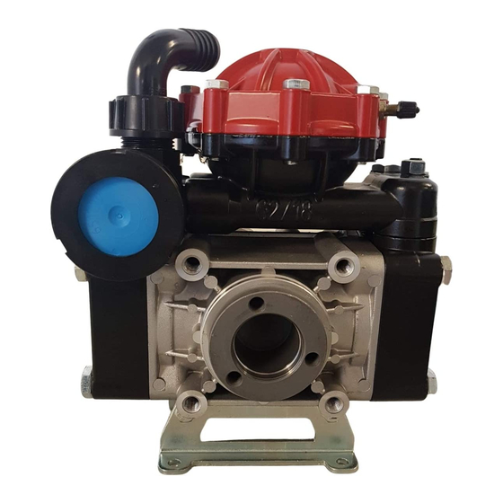
140° F - Max Water Temp
1" - Suction AR30
1 1/4" Suction AR40
1/2" NPT - Outlet
AR30 - 550
M
ODEL
AR30-SP
AR30-SP/A3/4
AR30-GR3/4-GCI
AR40 - 550
M
ODEL
AR40-SP
AR40-SP/A3/4
AR40-GR3/4-GCI
GCI - Pump with a mounted control unit.
DIAPHRAGM KITS
M
D
ODEL
ESCRIPTION
AR43285
BlueFlex
AR43283
Desmopan
AR43282
Buna
INSTRUCTION MANUAL
- S
-H
RPM
EMI
YDRAULIC
M
GPM M
AX
9.6
9.6
9.6
- S
-H
RPM
EMI
YDRAULIC
M
GPM M
AX
12.2
12.2
12.2
V
K
ALVE
ITS
M
D
ODEL
ESCRIPTION
AR1917
Valves
T
D
P
WO
IAPHRAGM
UMP
L/M
M
PSI
M
AX
IN
AX
36.2
580
36.2
580
36.2
580
T
D
P
WO
IAPHRAGM
UMP
L/M
M
PSI
M
AX
IN
AX
46.3
580
46.3
580
46.3
580
O-R
K
ING
ITS
M
D
ODEL
ESCRIPTION
AR1916
O-Rings
W
EIGHT
B
HP P
L
AX
AR
OWER
BS
40
2.9
20.5
40
2.9
20.5
40
2.9
33.0
W
EIGHT
B
HP P
L
AX
AR
OWER
BS
40
3.5
20.5
40
3.5
20.5
40
3.5
33.0
O
IL
M
D
ODEL
AR64532D
Oil
AR64532D-C Case (6)Oil
AR 30
AR 40
.
.
ESCRIPTION
Advertisement
Table of Contents

Related Manuals for Annovi Reverberi AR 30 Series


Summary of Contents for Annovi Reverberi AR 30 Series
- Page 1 AR 30 AR 40 140° F - Max Water Temp 1” - Suction AR30 1 1/4" Suction AR40 1/2” NPT - Outlet INSTRUCTION MANUAL AR30 - 550 YDRAULIC IAPHRAGM EIGHT GPM M HP P ODEL OWER AR30-SP 36.2 20.5 AR30-SP/A3/4 36.2 20.5 36.2...
- Page 2 AR30 AR40 AR30-EM230-1 AR30-SP/A3/4 AR30-SP 3 HP 230 Volt AR40-SP/A3/4 AR40-SP Single Phase Motor Pump with Pump with Base 3/4" Thru Shaft AR30-GR3/4-GCI AR30-CR3/4-GCI AR40-GR3/4-GCI AR40-CR3/4-GCI Pump with Gearbox & Pump with Gearbox Control Unit & Control Unit...
- Page 3 O t on Gearbox Kit AR1666: 4” o 5 6 H En n Gearbox Kit AR1636: 3/4” for 5-6HP En n Gearbox for four stroke engines Gearbox for four stroke engines with SAE J609a flange with SAE J609a flange Shaft Kit AR43394: 1 3/8” 6 pline Shaft Kit AR43393: 1 3/8”...
- Page 4 AR 0 M 0 1 0 olt Single Phase Motor 4 Pole 1700 RPM Operation IP54 Protection Against Rain and Splashing Water. L1 AND L2 ARE THE TERMINALS FOR THE CONNECTIONS OF THE WIRES FROM THE POWER CABLE AR30 EM 0 1 550 YDRAULIC IAPHRAGM EIGHT ODEL 36.2 AR30-...
-
Page 5: Control Unit Operation
Control Unit Control Unit o trol u ts are a a lable or eas lo a ressure co trol our s ra er s ste ese u ts clu e a a ual al e a a ustable ressure rel e al e to co trol ressure a l u ressure au e to... -
Page 6: Important Safety Information
IMPORTANT SAFETY INFORMATION Intended uses The pump is designed and constructed for incorporation in plants and machinery (spraying machines for the protective treatment of agricultural crops and garden plants). All other uses constitute misuse unless ap- proved by the manufacturer's technical service The pump must be used in a manner appropriate to its technical data (see “Technical Data”), and must not be modified or improperly used. - Page 7 Installation diagram (guideline) The following is a simplified illustration of the typical installation layout and is purely guideline. Control Unit by-pass Tank Agitation Control Unit Intake filter Pump Delivery line filter...
-
Page 8: Installation Instructions
INSTALLATION INSTRUCTIONS General guidelines on water supply connection To operate correctly, the diaphragm pump must draw in liquids from containers at atmospheric pressure. Do not supply the pump with pressurised liquids. For continuous duty, the pump should not draw in water by gravity from containers with liquid level at heights above 3 m. - Page 9 Safety recommendations for handling and lifting Before starting the operations, organise the intended working area so that the materials can be lifted and handled in safety. Unloading, loading, handling and lifting operations must be carried out by skilled, authorised, specifi cally trained staff.
- Page 10 Installation • The crankshaft may turn in either direction. • The water connection with the pump must be made using hoses of suitable diameter, in all case no less than that of the pump fittings, securing them to the fittings using good quality clamps. The intake hose must be coil-reinforced to prevent restrictions.
- Page 11 Safety recommendations for use Before start-up, the operator must perform the necessary safety checks. In the event of leaks from the pressurized pipes, stop the pump at once and fix the leak. Do not operate the pump above the limits set by the manufacturer to increase its performance. Preliminary checks If the pump has a pressure accumulator, check its level of inflation, see "Checking the inflation pressure".
- Page 12 Safety recommendations for maintenance Before doing any maintenance work, depressurise the water system and isolate the pump from all en- ergy sources. When the jobs are done, before restarting the pump, check that no tools, rags or other materials have been left close to moving parts or in hazardous zones.
-
Page 13: Maintenance Instructions
MAINTENANCE INSTRUCTIONS Table of lubricants The pump is delivered complete with high-performance 30 weight, non-detergent oil suitable for the intended ambient conditions (see "Environmental operating limits"). Inspecting the pump mounting Check that the pump's fixing screws have not become loose. If necessary, tighten them with the driving torque stated in the installation design. - Page 14 MAINTENANCE INSTRUCTIONS Checking the inflation pressure If the pump has a pressure accumulator, check its level of inflation, with the pump shutoff using an air chuck fitted with a pressure gauge. The ac cumulator is inflated by the manufacturer for use of the pump at its maximum pressure.
- Page 15 Pump Storage It is important to comply with the recommendations for storage in the operator's manual of the machine into which the pump is incorporated. For the pump itself, at the end of pumping operations it is essential to flush out the internal circuit by pump ing clean water.
-
Page 16: Troubleshooting
TROUBLESHOOTING The information provided is intended to provide guidance how to deal with malfunctions which may occur during use. Some of these procedures may be carried out by skilled staff, while others have to be performed at specialised service centres since they require the use of specific equipment as well as detailed knowledge of repair opera tions. - Page 17 TROUBLESHOOTING Remedy Problem Cause Oil seal on pump Replace the worn oil seal. shaft worn. Oil on pump body or base. Oil pressure inside pump too high. Restore correct oil level in tank. Pump using too much oil (oil flowing from delivery port) or oil Stop the pump at once.
- Page 18 A.R. NORTH AMERICA A.R. NORTH AMERICA AR 30 / AR 40 50 49 66 67 44 - 1 44 - 2 UP TO SERIAL NUMBER FROM SERIAL NUMBER 910400 910399 21 22 23 68 69 70 20 44 - 3 44 - 4 651670 available...
- Page 19 SP/A3/4 AR 30 / AR 40 AR30 31732 31733 AR40 33044 33045 Code Description Note Code Description Note 620011 Pump body 620230 Semi air chamber upper 620101 Head 629211 Semi air chamber upper / w-air valve 620102 Head 550194 Air chamber BlueFlex Diaphragm 621430 Bolt...
- Page 20 A.R. NORTH AMERICA A.R. NORTH AMERICA GI 40 / GIC40 AR 503 - AR 713 - AR 813 94 - 2 94 - 6 Code Description Note Code Description Note 620220 Relief valve body 329202 Seat GIC40 Guide assembly 130171 Plug 3/8”...
- Page 21 GI 40 / GIC 40 For GI 40 KIT 977 “I” KIT 982 “S” KIT 980“S” Build-in control unit and remote control AR 977 "I" AR 980 "S" AR 982 "S" Build in control Remote control Remote control Pos. Pos. Pos.
- Page 22 A.R. NORTH AMERICA A.R. NORTH AMERICA A.R. NORTH AMERICA A.R. NORTH AMERICA A.R. NORTH AMERICA A.R. NORTH AMERICA A.R. NORTH AMERICA A.R. NORTH AMERICA A.R. NORTH AMERICA A.R. NORTH AMERICA A.R. NORTH AMERICA A.R. NORTH AMERICA A.R. NORTH AMERICA A.R. NORTH AMERICA A.R.
- Page 23 A.R. NORTH AMERICA A.R. NORTH AMERICA AR 1666 : Gear Reduction Per - For: AR 30 - AR 303 - AR 403 Ø 3/4" Straight Keyed Shaft 153 - 2 94 - 1 Cod. Description Q.ty Note 540331 Seal 200390 Snap ring Øi 62 621130 Bearing 4 2960050 Bolt...
Need help?
Do you have a question about the AR 30 Series and is the answer not in the manual?
Questions and answers