Advertisement
Quick Links
140° F - Max Water Temp 1 1/2"
- Suction
1" - Outlet
AR80LFP - 550
m
odeL
AR80LFP-C
AR80LFP-SP
AR80LFP-AP-SP/C
AR80LFP-AP-C/C
AR80LFP-GR-GCI*
*Model comes standard with Viton diaphragms.
d
K
iAPHRAgm
iTS
m
odeL
AR43247
BlueFlex
AR43245
Desmopan
AR43244
NBR
AR43246
Viton
INSTRUCTION MANUAL
- S
-H
RPm
emi
ydRAuLic
m
gPm
m
L/m
Ax
Ax
20.2
76.4
20.2
76.4
20.2
76.4
20.2
76.4
20.2
76.4
V
K
ALVe
iTS
m
odeL
AR43138 Valves
316SS
AR 80 LFP
140° F - Max Water
Temp 1 1/2" - Suction
1/2" - Hose Barb Outlets
1" - Bypass Hose Barb
T
-d
HRee
iAPHRAgm
m
PSi
m
in
Ax
Ax
290
20
290
20
290
20
290
20
290
20
o-R
K
ing
iTS
m
d
odeL
eScRiPTion
AR43128
O-Rings
P
umP
B
HP P
AR
oweR
3.4
3.4
3.4
3.4
3.4
o
iL
m
odeL
AR64532D
AR64532D-C Case (6)Oil
w
eigHT
L
.
BS
30.8
30.8
30.8
30.8
40.0
d
eScRiPTion
Oil
Advertisement

Related Manuals for Annovi Reverberi AR 80 LFP


Summary of Contents for Annovi Reverberi AR 80 LFP
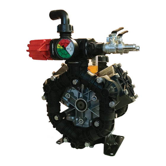
- Page 1 AR 80 LFP 140° F - Max Water 140° F - Max Water Temp 1 1/2” - Suction Temp 1 1/2” - Suction 1” - Outlet 1/2” - Hose Barb Outlets 1" - Bypass Hose Barb INSTRUCTION MANUAL AR80LFP - 550...
- Page 2 INSTALLATION INSTRUCTIONS Full Bypass Full Pressure Lever Position Lever Position Bypass Pressure / Bypass Lever Pressure utlet ust ent no ose Barbs e ote ount nlet ose Bar GS35V Control Unit Model No.AR3249006 C Version SP Version AP SP/C Version 1 3/8”...
- Page 3 CONTROL UNIT INSTRUCTIONS Red Pressure Adjustment Knob Bypass Hose Press/Bypass Barb Lever shown in Pressure Position Outlet Hose Barb 2 Places Remote Mount Inlet Hose Barb 1. When starting the pump, keep the control unit in the full bypass position until the pump has primed.
- Page 4 IMPORTANT SAFETY INFORMATION Intended uses The pump is designed and constructed for incorporation in plants and machinery (spraying machines for the protective treatment of agricultural crops and garden plants). All other uses constitute misuse unless ap- proved by the manufacturer's technical service The pump must be used in a manner appropriate to its technical data (see “Technical Data”), and must not be modified or improperly used.
- Page 5 Installation diagram (guideline) The following is a simplified illustration of the typical installation layout and is purely a guideline. Control Unit by-pass Tank Agitation Control Unit Intake filter Pump Delivery line filter...
- Page 6 INSTALLATION INSTRUCTIONS General guidelines on water supply connection To operate correctly, the diaphragm pump must draw in liquids from containers at atmospheric pressure. Do not supply the pump with pressurised liquids. For continuous duty, the pump should not draw in water by gravity from containers with liquid level at heights above 3 m.
- Page 7 Safety recommendations for handling and lifting Before starting the operations, organise the intended working area so that the materials can be lifted and handled in safety. Unloading, loading, handling and lifting operations must be carried out by skilled, authorised, specifi cally trained staff.
- Page 8 Installation • The crankshaft may turn in either direction. • The water connection with the pump must be made using hoses of suitable diameter, in all case no less than that of the pump fittings, securing them to the fittings using good quality clamps. The intake hose must be coil-reinforced to prevent restrictions.
- Page 9 Safety recommendations for use Before start-up, the operator must perform the necessary safety checks. In the event of leaks from the pressurized pipes, stop the pump at once and fix the leak. Do not operate the pump above the limits set by the manufacturer to increase its performance. Preliminary checks If the pump has a pressure accumulator, check its level of inflation, see "Checking the inflation pressure".
- Page 10 Safety recommendations for maintenance Before doing any maintenance work, depressurise the water system and isolate the pump from all en- ergy sources. When the jobs are done, before restarting the pump, check that no tools, rags or other materials have been left close to moving parts or in hazardous zones.
- Page 11 Table of lubricants The pump is delivered complete with high-performance 30 weight, non-detergent oil suitable for the intended ambient conditions (see "Environmental operating limits"). Inspecting the pump mounting Check that the pump's fixing screws have not become loose. If necessary, tighten them with the driving torque stated in the installation design. Inspecting the connections and pipes - Inspect the connections for leaks.
- Page 12 Pump Storage It is important to comply with the recommendations for storage in the operator's manual of the machine into which the pump is incorporated. For the pump itself, at the end of pumping operations it is essential to flush out the pump by pumping clean water.
- Page 13 TROUBLESHOOTING The information provided is intended to provide guidance how to deal with malfunctions which may occur during use. Some of these procedures may be carried out by skilled staff, while others have to be performed at specialised service centres since they require the use of specific equipment as well as detailed knowledge of repair opera tions.
- Page 14 TROUBLESHOOTING Remedy Problem Cause Oil seal on pump Replace the worn oil seal. shaft worn. Oil on pump body or base. Oil pressure inside pump too high. Restore correct oil level in tank. Pump using too much oil (oil flowing from delivery port) or oil Stop the pump at once.
- Page 15 A.R. NORTH AMERICA A.R. NORTH AMERICA AR60LFP / AR80LFP / AR 80 bp Attention! Assemble with grease between the plate and the membrane 19 20 18 - 1 18 - 2 18 - 3 18 - 4 SP/AP C/AP Appl. C 18 - 5 18 - 6 2021 AR North America...
- Page 16 BlueFlex diaphragms Pump and manufacturer AR 43244 identification. NBR diaphragms AR 42857 - AR 80 bp AR 43246 Suggested oil AR 43128 - AR 80 LFP Viton diaphragms AR 42805 O-Rings Valves - AR80bp Type AR 43245 AR 43138 Pos.
- Page 17 A.R. NORTH AMERICA A.R. NORTH AMERICA AR 60LFP GR-GCI / AR 80LFP GR-GCI Warning! Fit with molybdenum disul de grease between plate and diaphragm. 69 70 72 71 ∆ 16 - 1 16 - 2 16 - 3 16 - 4 Gear Box AR31185 Suggested Oil Type...
- Page 18 AR 60LFP GR-GCI / AR 80LFP GR-GCI Code Description Note Code Description Note 1880240 Pin 3240031 Manifold 3/8" G 660171 O-ring Ø 31.42x2.62 390292 O-ring Ø 28.25x2.62 Viton 394211 O-ring Ø 29.82x2.62 Viton 3240040 Manifold 3240391 Piston 3240030 Manifold 3240421 Plug 380211 Bolt SS T88* 720031 O-ring...
- Page 19 A.R. NORTH AMERICA AR 31185 : Gear Reduction Use of engine : 31185: B&S Vanguard 6.5 Kohler SH265 - CH270 Subaru E17 - 21 Honda GP160 - GX160 Ø 3/4" Straight Keyed Shaft 93 - 1 1.Lubricate the gasket (Ref. 1) on the pump adapter flange (Ref. 2). Slip the flange Cod.
- Page 20 A.R. NORTH AMERICA A.R. NORTH AMERICA GS 35 S GS35S GS35SV WARNING! Time the two holes using the tooth indicated in the position (A) 81 - 1 Code Description Note Code Description Note 3240440 Knob 2840890 O-ring Ø 14x2 3240410 Spring 2840891 O-ring Ø...
Need help?
Do you have a question about the AR 80 LFP and is the answer not in the manual?
Questions and answers