
Related Manuals for IBASE Technology ET980 Series


Summary of Contents for IBASE Technology ET980 Series
- Page 1 ET980 Series Intel ® 12th Gen. Core™ COM Express Type 6 Module User’s Manual Version 1.0 (March 2023)
- Page 2 No part of this publication may be reproduced, copied, stored in a retrieval system, translated into any language or transmitted in any form or by any means, electronic, mechanical, photocopying, or otherwise, without the prior written consent of IBASE Technology, Inc. (hereinafter referred to as “IBASE”). Disclaimer IBASE reserves the right to make changes and improvements to the products described in this document without prior notice.
- Page 3 0.1% by weight (1000 ppm) except for cadmium, limited to 0.01% by weight (100 ppm). • Lead (Pb) • Mercury (Hg) • Cadmium (Cd) • Hexavalent chromium (Cr6+) • Polybrominated biphenyls (PBB) • Polybrominated diphenyl ether (PBDE) ET980 Series User’s Manual...
- Page 4 Danger of explosion if the internal lithium-ion battery is replaced by an incorrect type. Replace only with the same or equivalent type recommended by the manufacturer. Dispose of used batteries according to the manufacturer’s instructions or recycle them at a local recycling facility or battery collection point. ET980 Series User’s Manual...
- Page 5 Software in use (such as OS and application software, including the • version numbers) If repair service is required, please login in the RMA system of the website or and contact your distributor or sales representative for assistance. ET980 Series User’s Manual...
-
Page 6: Table Of Contents
Intel® Management Engine Drivers Installation ......... 29 Intel® Serial IO Drivers Installation ............ 32 Chapter 4 BIOS Setup ............35 Appendix ..................57 I/O Port Address Map ................ 58 Interrupt Request Lines (IRQ) ............60 Watchdog Timer Configuration ............61 ET980 Series User’s Manual... -
Page 7: Chapter 1 General Information
Chapter 1 General Information The information provided in this chapter includes: Features • Packing List • • Optional Accessories Specifications • Block Diagram • Board View • • Board Dimensions... -
Page 8: Introduction
● 4x USB 3.2, 8x USB 2.0, 2x SATA III, 2x COM ● 1x PCI-E(x8) [2x PCI-E(4x) signal**], 1x PCI-e(x4), 4x PCI-E(x1) to carrier board **Only one PCI-E (x8) signal from Alder Lake-P 28W/15W CPU skus** ● Digital I/O, TPM (2.0), Watchdog timer ET980 Series User’s Manual... -
Page 9: Packing List
4x USB 3.1 (Gen 2) via carrier board Serial ATA 2x SATA III via carrier board Audio Built-in HD Audio controller 1x PCI-E(x8) [(Gen. 4) (PCIe(4x)+ PCIe(4x)], 1xPCI-E(x4) Expansion Slot (Gen. 3), 4x PCI-E(x1) (Gen. 2) to carrier board ET980 Series User’s Manual... - Page 10 • Operation: 0 ~ 60 °C (32 ~ 140 °F) Temperature • Storage: -20 ~ 80 °C (-4 ~ 176 °F) Relative 10 ~ 95 %, non-condensing Humidity All specifications are subject to change without prior notice. ET980 Series User’s Manual...
-
Page 11: Block Diagram
General Information Block Diagram ET980 Series User’s Manual... -
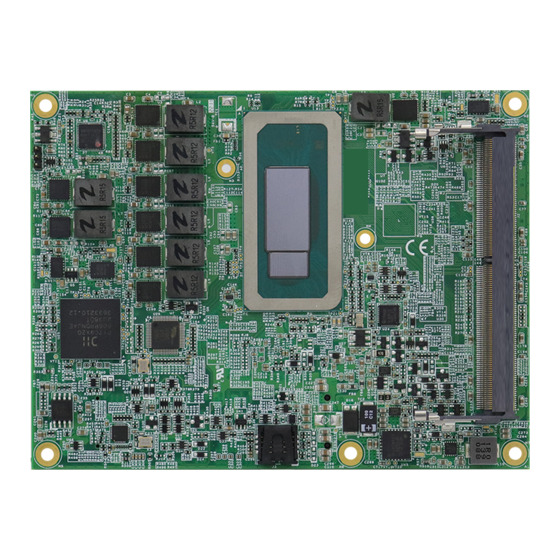
Page 12: Board View
Board View Top View ET980 Series User’s Manual... - Page 13 General Information Bottom View *The pictures are for reference only. Some minor components may differ. ET980 Series User’s Manual...
-
Page 14: Dimensions
Dimensions Unit: mm ET980 Series User’s Manual... -
Page 15: Chapter 2 Hardware Configuration
Chapter 2 Hardware Configuration This section provides information on jumper settings and connectors on the ET980 in order to set up a workable system. On top of that, you will also need to install crucial pieces such as the CPU and the memory before using the product. The topics covered are: •... -
Page 16: Installations
Gently push the module in an upright position until the clips of the slot close to hold the module in place when the module touches the bottom of the slot. To remove the module, press the clips outwards with both hands, and the module will pop-up. ET980 Series User’s Manual... -
Page 17: Switch & Connector Locations
Hardware Configuration Switch & Connector Locations TOP VIEW BOTTOM VIEW Remarks: SW1: ATX / AT Mode J2, J4: SO-DIMM Sockets COM_E_AB1, COM_E_CD1: COM Express Module Type 6 Connector ET980 Series User’s Manual... -
Page 18: Switch & Connector Quick Reference
Switch & Connector Quick Reference Function Jumper Page ATX / AT Mode COM Express Module (COM_E_AB1, Type 6 Connector COM_E_CD1) 2.3.1 ATX / AT Mode (SW1) Function Pin closed Illustration P1-OFF (default) P1-ON ET980 Series User’s Manual... -
Page 19: Com Express Module Type 6 Connector
SATA1_RX+ PCIE_RX6+ PCIE_TX6+ SATA0_RX- SATA1_RX- PCIE_RX6- PCIE_TX6- GND (FIXED) GND (FIXED) GND (FIXED) GND (FIXED) PCIE_RX7+ PCIE_TX7+ PCIE_RX7- PCIE_TX7- SUS_S5# PWR_OK DDI1_HPD RSVD RSVD DDI1_PAIR0+ BATLOW# RSVD DDI1_PAIR0- SATA_ACT# RSVD RSVD HDA_SYNC DDI1_PAIR1+ HDA_RST# HDA_SDIN0 DDI1_PAIR1- ET980 Series User’s Manual... - Page 20 A70 GND (FIXED) GND (FIXED) C70 GND (FIXED) D70 GND (FIXED) LVDS_A0+/ RSVD RSVD LVDS_B0+ eDP_TX2+ LVDS_A0-/ RSVD RSVD LVDS_B0- eDP_TX2- LVDS_A1+/ LVDS_B1+ C73 GND D73 GND eDP_TX1+ LVDS_A1-/ RSVD RSVD LVDS_B1- eDP_TX1- LVDS_A2+/ RSVD RSVD LVDS_B2+ eDP_TX0+ ET980 Series User’s Manual...
- Page 21 A107 VCC_12V B107 VCC_12V C107 VCC_12V D107 VCC_12V A108 VCC_12V B108 VCC_12V C108 VCC_12V D108 VCC_12V A109 VCC_12V B109 VCC_12V C109 VCC_12V D109 VCC_12V A110 GND (FIXED) B110 GND (FIXED) C110 GND (FIXED) D110 GND (FIXED) ET980 Series User’s Manual...
- Page 22 This page is intentionally left blank. ET980 Series User’s Manual...
-
Page 23: Chapter 3 Drivers Installation
Chapter 3 Drivers Installation This chapter introduces installation of the following drivers: • Intel ® Chipset Software Installation Utility • Graphics Driver HD Audio Driver • LAN Driver • • Intel® Management Engine Drivers Intel® Serial IO Drivers •... -
Page 24: Introduction
INF files for Plug & Play function for Intel chipset components. Follow the instructions below to complete the installation. Insert the disk enclosed in the package with the board. Click Intel on the left pane and then Intel(R) AlderLake-P Chipset Drivers on the right pane. ET980 Series User’s Manual... - Page 25 Driver Installation Click Intel(R) Chipset Software Installation Utility. When the Welcome screen to the Intel ® Chipset Device Software appears, click Next. ET980 Series User’s Manual...
- Page 26 Accept the software license agreement. On the Readme File Information screen, click Install. The driver has been completely installed. Click Finish. ET980 Series User’s Manual...
-
Page 27: Graphics Driver Installation
Driver Installation Graphics Driver Installation Click Intel on the left pane and then Intel(R) AlderLake-P Chipset Drivers on the right pane. Click Intel(R) HD Graphics Driver. ET980 Series User’s Manual... - Page 28 On the next screen shown below, click Begin installation. Click I agree. ET980 Series User’s Manual...
- Page 29 Driver Installation Click Start. When installation is complete, restart your system in order to apply the driver changes. ET980 Series User’s Manual...
-
Page 30: Hd Audio Driver Installation
- Intel_Sound.bat in the directory shown in the picture below: I-12_Gen-P-1.0\Intel\AlderLake-P\Sound\Windows 10_11 Right-click Intel_Sound.bat and run the batch file as administrator. After running the batch file, install the audio drivers. Click Intel on the left pane and then Intel(R) AlderLake-P Chipset Drivers on the right. ET980 Series User’s Manual... - Page 31 Driver Installation Click Realtek High Definition Audio Drivers. On the Welcome screen of the InstallShield Wizard, click Next. When the InstallShield Wizard has completed the installation, restart your computer to be able to use the program. ET980 Series User’s Manual...
-
Page 32: Lan Driver Installation
LAN Driver Installation Click Intel on the left pane and then Intel(R) AlderLake-P Chipset Drivers on the right pane. Click Intel(R) PRO LAN Network Drivers.. ET980 Series User’s Manual... - Page 33 Driver Installation Click Install Drivers and Software. On the Welcome screen appears, click Next. Accept the license agreement and click Next. ET980 Series User’s Manual...
- Page 34 In the Setup Options, click Next. Click Install. Install wiazard has completed the installation. Click Finish. ET980 Series User’s Manual...
-
Page 35: Intel® Management Engine Drivers Installation
Driver Installation Intel® Management Engine Drivers Installation Click Intel on the left pane and then Intel(R) AlderLake-P Chipset Drivers on the right pane. Click Intel(R) ME Drivers. ET980 Series User’s Manual... - Page 36 When the Welcome screen appears, click Next. Accept the license agreement and click Next until the installation starts. ET980 Series User’s Manual...
- Page 37 Driver Installation Click Next to install to the default folder or click Change to choose another destination folder. When installation has been completed, click Finish. ET980 Series User’s Manual...
-
Page 38: Intel® Serial Io Drivers Installation
Intel® Serial IO Drivers Installation Click Intel on the left pane and then Intel(R) AlderLake-P Chipset Drivers on the right pane. Click Intel(R) Serial IO Drivers. ET980 Series User’s Manual... - Page 39 Driver Installation Agree with the license terms and conditions and click Install. Installation has been successfully completed. Click Restart. ET980 Series User’s Manual...
- Page 40 This page is intentionally left blank. ET980 Series User’s Manual...
-
Page 41: Chapter 4 Bios Setup
Chapter 4 BIOS Setup This chapter describes the different settings available in the AMI BIOS that comes with the board. The topics covered in this chapter are as follows: Main Settings • • Advanced Settings Chipset Settings • Security Settings •... - Page 42 These defaults have been carefully chosen by both AMI and your system manufacturer to provide the absolute maximum performance and reliability. Changing the defaults could make the system unstable and crash in some cases. ET980 Series User’s Manual...
- Page 43 System Language Choose the system default language. Sets the date. Use the <Tab> key to switch between System Date the date elements. Set the time. Use the <Tab> key to switch between System Time the time elements. ET980 Series User’s Manual...
- Page 44 4.4 Advanced Settings This section allows you to configure, improve your system and allows you to set up some system features according to your preference. 4.4.1 CPU Configuration ET980 Series User’s Manual...
- Page 45 Options: 3, 2, 1 Number of cores to enable in each processor Active Efficient-cores package. Options: 7, 6, 5, 4, 3, 2, 1 Enables / Disables Hyperthreading Hyper-Threading Technology. Enables / Disables AES (Advanced Encryption Standard). ET980 Series User’s Manual...
- Page 46 4.4.2 Power & Performance ET980 Series User’s Manual...
- Page 47 Configurable TDP Mode as Nominal/Level/Leve2/Deactivate TDP Boot Mode selection. Deactivate option will set MSR to Nominal and MMIO to Zero. 4.4.3 PCH-FW Configuration Displays the information of PCH firmware, such as the firmware version, mode, and SKU. ET980 Series User’s Manual...
- Page 48 TPM 2.0 will restrict support to TPM 2.0 devices only. Device Select Auto will support both with the default being • set to TPM 2.0 deices if not found, and TPM 1.2 device will be enumerated. ET980 Series User’s Manual...
- Page 49 BIOS Setup 4.4.4 ACPI Settings BIOS Setting Description Enables / Disables the system ability to hibernate Enable Hibernation (OS/S4 Sleep State). This option may be not effective with some OS. ET980 Series User’s Manual...
- Page 50 Panel Type 768 / 1440 x 900 / 1600 x 900 / 1600 x 1200 / 1680 x 1050 / 1920 x 1080 / 1920 x 1200 LVDS Backlight Options: 0 (Min) ~ 7 (Max) Control ET980 Series User’s Manual...
- Page 51 BIOS Setup 4.4.6 F81966 Super IO Configuration ET980 Series User’s Manual...
- Page 52 4.4.7 F81804SEC Super IO Configuration ET980 Series User’s Manual...
- Page 53 BIOS Setup 4.4.8 Hardware Monitor Displays the information of the computer health status. 4.4.9 AMI Graphic Output Protocol Policy User Select Monitor Output by Graphic Output Protocol. ET980 Series User’s Manual...
- Page 54 Maximum time the device will take before it properly reports itself to the Host Controller. Device power-up “Auto” uses default value: for a root port it is 100 delay ms, for a hub port, the delay is taken from hub descriptor. ET980 Series User’s Manual...
- Page 55 BIOS Setup 4.4.11 Network Stack Configuration ET980 Series User’s Manual...
- Page 56 4.4.12 NVMe Configuration ET980 Series User’s Manual...
- Page 57 BIOS Setup 4.5 Chipset Settings 4.5.1 System Agent (SA) Configuration BIOS Setting Description Memory Configuration Memory Configuration Parameters VT-d Enables / Disables VT-d capability. ET980 Series User’s Manual...
- Page 58 ET980 Series User’s Manual...
- Page 59 BIOS Setup PCH-IO Configuration ET980 Series User’s Manual...
- Page 60 User Password Sets a user password. Secure boot feature is Active if Secure Boot is enabled. Platform Key(PK) is enrolled and the Secure Boot system is in user mode. The mode change requires platform reset. ET980 Series User’s Manual...
- Page 61 65535 (0xFFFF) means indefinite waiting. Bootup NumLock Selects the keyboard NumLock state. State Quiet Boot Enables / Disables Quiet Boot option. Boot mode select Selects a Boot mode, Legacy / UEFI. Boot Option Priorities Sets the system boot order priorities. ET980 Series User’s Manual...
- Page 62 Restores / Loads defaults values for all the setup Restore Defaults options. Save as User Defaults Saves the changes done so far as User Defaults. Restores the user defaults to all the setup Restore User Defaults options. ET980 Series User’s Manual...
-
Page 63: Appendix
Appendix This section covers the following topics: A. I/O Port Address Map B. Interrupt Request Lines (IRQ) C. Watchdog Timer Configuration... -
Page 64: I/O Port Address Map
0x0000002C-0x0000002D Programmable interrupt controller 0x00000030-0x00000031 Programmable interrupt controller 0x00000034-0x00000035 Programmable interrupt controller 0x00000038-0x00000039 Programmable interrupt controller 0x0000003C-0x0000003D Programmable interrupt controller 0x000000A0-0x000000A1 Programmable interrupt controller 0x000000A4-0x000000A5 Programmable interrupt controller 0x000000A8-0x000000A9 Programmable interrupt controller 0x000000AC-0x000000AD Programmable interrupt controller ET980 Series User’s Manual... - Page 65 PCI Express Root Complex 0x00000040-0x00000043 System timer 0x00000050-0x00000053 System timer 0x0000EFA0-0x0000EFBF Intel(R) SMBus - 51A3 0x00002000-0x000020FE Motherboard resources 0x00003090-0x00003097 Standard SATA AHCI Controller 0x00003080-0x00003083 Standard SATA AHCI Controller 0x00003060-0x0000307F Standard SATA AHCI Controller 0x00001854-0x00001857 Motherboard resources ET980 Series User’s Manual...
-
Page 66: Interrupt Request Lines (Irq)
Microsoft ACPI-Compliant System IRQ 41 Trusted Platform Module 2.0 IRQ 4294967293 Intel(R) PCI Express Root Port #10 - 51B1 IRQ 4294967288 Standard SATA AHCI Controller Intel(R) USB 3.10 eXtensible Host IRQ 4294967285 Controller - 1.20 (Microsoft) ET980 Series User’s Manual... -
Page 67: Watchdog Timer Configuration
**endptr; char SIO; printf("Fintek 81804 watch dog program\n"); SIO = Init_F81804(); if (SIO == 0) printf("Can not detect Fintek 81804, program abort.\n"); return(1); }//if (SIO == 0) if (argc != 2) printf(" Parameter incorrect!!\n"); return (1); ET980 Series User’s Manual... - Page 68 &= ~0x01; Set_F81804_Reg(0xFA, bBuf); //disable WDTO output bBuf = Get_F81804_Reg(0xF5); bBuf &= ~0x20; bBuf |= 0x40; Set_F81804_Reg(0xF5, bBuf); //disable WDT //--------------------------------------------------------------------------- //--------------------------------------------------------------------------- // THIS CODE AND INFORMATION IS PROVIDED "AS IS" WITHOUT WARRANTY OF ANY ET980 Series User’s Manual...
- Page 69 F81804_BASE = 0x00; result = F81804_BASE; Init_Finish: return (result); //--------------------------------------------------------------------------- void Unlock_F81804 (void) outportb(F81804_INDEX_PORT, F81804_UNLOCK); outportb(F81804_INDEX_PORT, F81804_UNLOCK); //--------------------------------------------------------------------------- void Lock_F81804 (void) outportb(F81804_INDEX_PORT, F81804_LOCK); //--------------------------------------------------------------------------- void Set_F81804_LD( unsigned char LD) Unlock_F81804(); outportb(F81804_INDEX_PORT, F81804_REG_LD); outportb(F81804_DATA_PORT, LD); Lock_F81804(); //--------------------------------------------------------------------------- ET980 Series User’s Manual...
- Page 70 F81804_DATA_PORT (F81804_BASE+1) //--------------------------------------------------------------------------- #define F81804_REG_LD 0x07 //--------------------------------------------------------------------------- #define F81804_UNLOCK 0x87 #define F81804_LOCK 0xAA //--------------------------------------------------------------------------- unsigned int Init_F81804(void); void Set_F81804_LD( unsigned char); void Set_F81804_Reg( unsigned char, unsigned char); unsigned char Get_F81804_Reg( unsigned char); //--------------------------------------------------------------------------- #endif // F81804_H ET980 Series User’s Manual...
Need help?
Do you have a question about the ET980 Series and is the answer not in the manual?
Questions and answers