Table of Contents
Advertisement
Quick Links
Advertisement
Table of Contents

Related Manuals for NORDICCO NORTHERN AIR AMPLIFY


Summary of Contents for NORDICCO NORTHERN AIR AMPLIFY
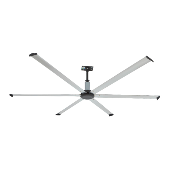
- Page 1 INSTALLATION MANUAL NORTHERN AIR ® AMPLIFY ENGLISH Vers. 1.0...
-
Page 2: Table Of Contents
® NORTHERN AIR AMPLIFY Table of Contents Overhead Ceiling Fans Quick Start Guide Step 1 - Step 12 Installation, Operation and Maintenance Manual General Information Required Tools Please read and save these instructions for future reference. Read carefully before attempting to assemble, install, General Safety Information operate or maintain the product described. -
Page 3: Quick Start Guide
Quick Start Guide STEP #2 - MOTOR INSTALLATION REFER TO INSTALLATION MANUAL FOR COMPLETE INSTALLATION INSTRUCTIONS. QUICK START GUIDE DOES NOT REPLACE INSTALLATION MANUAL INSTRUCTIONS. M4 - 0.7 x 10 MACHINE SCREW DOWNTUBE AND MOUNT ASSEMBLY STEP #1 - MOUNT INSTALLATION MOTOR INSTALLATION •... - Page 4 STEP #4 - AIRFOIL INSTALLATION STEP #7 - MOTOR CABLE CONNECTION TO VFD MOTOR CABLE CONNECTION TO VFD • GO TO SECTION MECHANICAL INSTALLATION IMPORTANT: PLUGS MUST BE FULLY SEATED AND IN PROPER ORIENTATION FOR FAN OPERATION HALL CABLE COLOR MOTOR POWER PINOUT REFERENCE TORQUE TO 25 FT LBF...
- Page 5 STEP #10 - FAN NETWORKING - IF WIRED INSTALLATION STEP #11 - CONTROLS INSTALLATION - IF WIRED INSTALLATION FIRST FAN IN SERIES ALL OTHER FANS IN SERIES FIRST FAN IN DAISY-CHAIN SURFACE MOUNT KEYPAD CONTROL (HMI) • GO TO SECTION FAN NETWORKING •...
-
Page 6: General Information
General Information assumes responsibility of the fan and accessories while in storage The manufacturer will not be responsible General Safety Information for damage during storage These suggestions are WARNING IMPORTANT: To reduce the risk of fire, electric shock, or provided solely as a convenience to the user injury to persons, AMPLIFY fans must be installed with This appliance can be used by children aged from 8 Indoor - The ideal environment for the storage of... - Page 7 Fan Components NOTE: Hardware quantities listed below indicate what Optional Fan Components is required to complete installation Hardware kits may Verify that all of the following parts and hardware I-Beam Mounting Kit (Optional) include extra fasteners as a convenience have been received prior to beginning installation Contact your local representative or the manufacturer if replacement parts are required NOTE: Additional parts (provided by others) may be...
-
Page 8: Pre-Installation
Pre-Installation Minimum Spacing Requirements Pre-Installation Checks If the fan is to be mounted in an area where materials or equipment may be elevated into its IMPORTANT: Consult all applicable national and local path, ensure that the floor is marked or painted codes to ensure that all necessary code requirements to alert personnel of the overhead location of the are met It is the sole responsibility of the installer to... - Page 9 Mechanical Installation Steel Truss Mounting Kit ft∙lbf (108 5 N∙m) STRUCTURAL STEEL ANGLES IMPORTANT: A Structural Engineer must perform (BY OTHERS) STEEL TRUSS / BAR JOIST Mounting Installation Hardware/Tools Needed (Not Included): thorough evaluation of mounting structure and • Torque Wrench determine final mounting requirements before fan is DANGER •...
-
Page 10: Wood Beam Mounting
Wood Beam Mounting Kit Motor/Hub to Downtube Installation M14 NYLON LOCKNUT (BY OTHERS) (For Beams 115-225 mm Wide) Required Loose Components (Included): WASHER IMPORTANT: A Structural Engineer must perform WOOD BEAM • Motor/Hub Assembly (1) BRACKET DOWNTUBE AND MOUNT ASSEMBLY thorough evaluation of mounting structure and •... -
Page 11: Safety Retention Cable Installation
Gripple ® Hardware (Optional) Install the supplied (2) grade 8 hex bolts into the From the top of the downtube, pull the safety locknuts attached to the downtube Torque the retention cable until it is taut inside the downtube Components required: Insert the loose end of the safety cable into the bolts to a value of 33 ft∙lbf (44 75 N∙m) ®... -
Page 12: Guy Wire Installation
Gripple ® Hardware (Optional) Guy Wire Installation IMPORTANT: Steel cable clamps consist of two parts: 4 Place a level against the downtube and tighten all (4) turnbuckles by hand in a crisscross pattern IMPORTANT: Guy wires must be installed 45º to 60º the u-bolt and the saddle Steel cable clamps must be IMPORTANT: Guy wires must be installed 45º... -
Page 13: Hub Plate Installation
Fire System Integration Install one winglet per airfoil blade using the screw locknuts Re-use increases the risk of locknuts loosening bosses located in each blade on the opposite end during operation, which may result in unwanted noise Fire System Integration (Optional) from the mounting holes Use a #2 phillips bit to and/or unsafe operation of the fan Contact your local IMPORTANT: The fire alarm relay should only be... -
Page 14: Electrical Installation
Motor Power and Ground Cable Connection Electrical Installation Motor Cable Connection IMPORTANT: The motor power, motor ground, and hall sensor cables are not long enough to reach the VFD Using a phillips screwdriver, remove the black circuit board from the rear side If the cables are not plastic cover on the front side of the VFD and set properly routed to the front of the VFD, the motor must aside... -
Page 15: Power Wiring
Hall Sensor Cable Connection Power Wiring Without Optional Electrical Plug If the fan is not supplied with the optional DANGER electrical plug, refer to the wiring diagrams below Always disconnect, lock and tag power source before to complete power wiring installing or servicing. -
Page 16: Communication Wiring
Communication Wiring a Connect a shielded CAT-5/6 control cable to the first fan in the daisy-chain using steps 1-3 IMPORTANT: Amplify fans not installed with Northern above Modbus Address Settings - Dipswitch 3 Sky must be installed with the supplied CAT-5/6 IMPORTANT: Positions 6 - 8 are used to set parameters b Plug an additional CAT-5/6 control cable into Modbus... -
Page 17: First Fan
First Fan All Remaining Fans Modbus Address Settings - Dipswitch 3 Set dipswitch 2 as shown below Dipswitch 2 is Modbus Position Position Position Position Position Position Number Address 6, 7, 8 used to set parameters that improve network RESERVED FOR HVLS FAN CONTROLS function and will need to be adjusted for all fans in the network except for the first fan Position 1 –... -
Page 18: Operation And Maintenance
All Remaining Fans Operation And Maintenance Pre-Start-Up Checks Fan Maintenance NOTE: Installation and maintenance are to be Disconnect and lock-out all power switches to fan performed only by qualified personnel who are familiar Check all fasteners on the ceiling mount, mounting with local codes and regulations and have experience kit, blades, VFD, motor and accessories for with this type of equipment... - Page 19 Downloads Other manuals as well as manuals in other languages can be downloaded from our website: www.nordicco.eu/downloads Address contact +45 73 70 90 83 Nordicco A/S info@nordicco.eu Strevelinsvej 22 www.nordicco.eu 7000 Fredericia Comp. Reg. No.: Denmark DK36085118...
Need help?
Do you have a question about the NORTHERN AIR AMPLIFY and is the answer not in the manual?
Questions and answers