
Subscribe to Our Youtube Channel
Related Manuals for NORDICCO NORTHERN AIR MINI


Summary of Contents for NORDICCO NORTHERN AIR MINI
- Page 1 INSTALLATION MANUAL INSTALLATIONSMANUAL INSTALLATIONSHANDBUCH NORDICCO NORTHERN AIR MINI ® ENGLISH - DANSK - DEUTSCH Vers. 2.0...
-
Page 2: Table Of Contents
Content/Indholdsfortegnelse/Inhaltsverzeichnis English ..........................1 Caution & Safety ........................... 1 Introduction ........................... 2 Pre-Installation ..........................5 Installing the fan ........................... 8 Information ..........................14 Dansk ..........................16 Generel sikkerhedsinformation ....................16 Introduktion ..........................17 Før installationen ........................20 Installation af ventilatoren ......................23 Information .......................... -
Page 3: English
2. Do not damage existing wiring and other hidden utilities/devices when cutting or drilling into a wall or ceiling. 3. Use this unit only in the manner intended by the manufacturer. If you have questions, contact Nordicco A/S or a distributor. Mounting of and replacement of parts of the suspension system must be performed by the manufacturer, its service agent, or suitably qualified persons. -
Page 4: Introduction
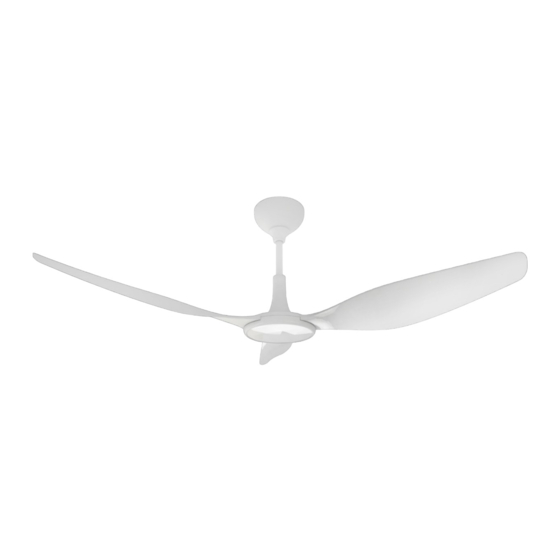
Introduction Thanks for choosing our products. The NORTHERN AIR ® MINI fan is an efficient, economical, and stylish choice. It's energy-saving, eco-friendly design brings excellent airflow to your space. We assure you this appliance will make space more comfortable in the near future. your Fan Outline 5 ft / 1,5 m... - Page 5 Installation Precautions 1. Installation of this fan requires a proper platform which can support the weight of fan plus installers, such as an aerial work platform. 2. Please switch off all power before installation to avoid the risk of electric shock. 3.
- Page 6 The Placement & Clearance between Fan and Obstructions A. The tip of an airfoil needs at least 2 ft (0,6 m) distance to any equipment/obstacles. B. The fan needs at least 8.17 ft (2,5 m) distance to the floor. C. The tip of the airfoil needs at least 0.98 ft (0,3 m) distance from beam / ceiling and no obstacles. D.
-
Page 7: Pre-Installation
Pre-Installation Inside the box Motor*1 Fixed Bracket*1 Yoke*1 Extension Tube Unit*1 Canopy*1 Circuit Box Unit*1 Remote Control *1 Airfoil Bolt Kit (M6 20L Bolt Kit) Closed-End Wire Connector*6 Standard Allen Wrench Kit Airfoil *3 NORTHERN AIR ® MINI FAN Installation Manual... - Page 8 Tools Required for Installation Mechanical Installation Electrical Installation Yoke Installation Secure the yoke to the Guy wire cutter Utility Knife Torque wrench 4.9-24.51 Nm. (50-250 Multimeter mounting structure with Crimping Pliers Kgf.cm) for inspection purpose suitable hardware (We Pair if #10 to #24 AWG Standard Allen wrench set recommend M6 bolt kits) strippers...
- Page 9 Pre-Installation Checklist Equipped with appropriate mounting kit for roof pitch. The fan is designed to be installed on straight ceilings. The mounting structure is approved by structural engineers. The mounting system must be able to withstand the torque generated by the fan. Familiarity with the functions of the safety cable.
-
Page 10: Installing The Fan
Installing the fan Installation Method 1-1 Secure yoke to the mounting structure with suitable hardware. * We recommend M6 bolt kits. 2-1 Take out the motor unit and the extension tube unit. Loosen the bolt kits of the extension tube unit. 2-2¨Pass through the extension tube unit with motor wire and safety cable. - Page 11 4-1 Slide the motor unit into the yoke. 4-2 Secure all fixed bracket parts in sequence. *Recommended Tightening Torque: 5 Nm. (50 Kgf.cm) 5-1 Separate circuit box unit and bracket. 5-2 Slide the bracket into yoke then secure it. *Recommended Tightening Torque: 5 Nm.
- Page 12 6-1 Use a wire connector to connect the corresponding red/yellow/black wires both from the circuit box and the motor. 6-2 Install the safety cable to the yoke with bolt kit. *Recommended Tightening Torque: 5 Nm. (50 Kgf.cm) The antenna must not be entangled with any wires and covered in canopy.
- Page 13 9-1 Loosen attach bolt kits on yoke, raise the canopy, then secure it to the fixed bracket. *Make sure all wires and safety cable are tucked in the canopy. 10-1 Align two mounting holes in each airfoil with the motor and secure it with airfoil bolt kit.
- Page 14 Fan Connection Warning • To avoid the risk of electric shock, please make sure that the wiring is in good electrical condition and all electricity supply should be disconnected. Above wiring should be implemented by a qualified electrician. • To avoid the risk of electric shock, please make sure that all wires are insulated properly before the fan is turned on.
- Page 15 RF Remote Control BUTTON FUNCTION Press each button to turn on the fan, then you can set air volume. The numbers increase air volume from low to high in numerical order (1 is the lowest, 6 is the highest volume). Press each button and the fan will give a short beep indicating that you activated the fan successfully.
-
Page 16: Information
▲ WARNING – Please use this unit in accordance with manufacturer instructions. If you have any questions, please contact NORDICCO ® ▲ WARNING – Turn the power off before performing maintenance or cleaning the unit. Make sure the power cannot be accidentally switched on during this procedure. - Page 17 If the wires were not installed, Nordicco A/S recommends the wire installation to be performed followed by another check. Please contact customer service if any wobbling persists.
-
Page 18: Dansk
2. Beskadig ikke eksisterende ledninger og andre skjulte hjælpemidler/enheder, når du skærer eller borer i en væg eller et loft. 3. Brug kun dette system på den måde, som producenten har tiltænkt. Har du spørgsmål, kontakt Nordicco A/S eller en forhandler. Montering af ophængningssystemet og udskiftning af dele af sikkerhedsophænget skal udføres af producenten, dennes serviceagent eller passende kvalificerede personer. -
Page 19: Introduktion
Introduktion Tak for at vælge vores produkter. NORTHERN AIR® MINI ventilatoren er et effektivt, økonomisk og stilfuldt valg. Det er energibesparende, har et miljøvenligt design og skaber en fremragende luftstrøm i dit rum. Denne ventilator vil gøre dit lokale mere behageligt i den nærmeste fremtid. Fan Outline 1,5 m/5 ft. - Page 20 Generel sikkerhedsinformation 1. Installation af denne ventilator kræver en ordentlig platform, som kan bære vægten af ventilatoren plus installatører, såsom en arbejdsplatform. 2. Sluk for al strøm før installation for at undgå risikoen for elektrisk stød. 3. Al ledningskonstruktion skal overholde de nationale elektriske regler, standarder og den lokale elektriske lovgivning og skal installeres af professionelle teknikere eller personale.
- Page 21 Placering og afstand mellem ventilator og forhindringer A. Spidsen af en vinge skal have mindst 0,6 m (2 ft.) afstand til udstyr/forhindringer. B. Ventilatoren skal have en afstand på mindst 2,5 m (8.17 ft.) til gulvet. C. Spidsen af vingen skal have mindst 0,3 m (0,98 ft.) afstand fra bjælke/loft og ingen forhindringer. D.
-
Page 22: Før Installationen
Før installationen Præ-installation Hvad indeholder kassen? Motor*1 Fixed Bracket*1 Yoke*1 Extension Tube Unit*1 Canopy*1 Circuit Box Unit*1 Remote Control *1 Airfoil Bolt Kit (M6 20L Bolt Kit) Closed-End Wire Connector*6 Standard Allen Wrench Kit Airfoil *3 NORTHERN AIR ® MINI FAN Installation Manual... - Page 23 Påkrævet værktøj og tilbehør Mekanisk installation Elektrisk installation Yoke installation yoken Fastgør Stålwire-tang til klipning af Schweizer kniv sikkerhedswire Multimeter monteringsstrukturen Momentnøgle 4,9-24,51 Nm. (50-250 Krympetænger med passende hardware Kgf.cm) til inspektionsformål Par hvis #10 til #24 AWG- (vi anbefaler M6 boltsæt) Standard unbrakonøglesæt strippere Standard skruenøgle/fatningssæt...
- Page 24 Præ installations tjek Udstyret med passende monteringssæt til taghældning. Ventilatoren er designet til at blive installeret på lige lofter. Monteringsstrukturen er godkendt af konstruktionsingeniører. Monteringssystemet skal kunne modstå det drejningsmoment, der genereres af ventilatoren. Kendskab til sikkerhedskablets funktioner. Til ventilatorinstallationen skal vingerne være mindst 2,5 meter (8,17 ft.) over jorden. (Se venligst afsnittet "Placering og afstand mellem ventilator og forhindringer") Til ventilatorinstallationen skal afstanden mellem vingerne og andre genstande/bygningsstruktur være mindst 0,6 meter (2 ft.).
-
Page 25: Installation Af Ventilatoren
Installation af ventilatoren Installations metode yoken 1-2 Fastgør til monteringsstrukturen med passende hardware. * Vi anbefaler M6 boltesæt. 2-1 Tag motorenheden og forlængerrørsenheden ud. Løsn boltesættene på forlængerrørsenheden. 2-2 Før gennem forlængerrørsenheden med motorledning og sikkerhedskabel. 2-3 Indsæt motorens aksel mellem to forlængerrørsklemmer, og fastgør derefter sikkerhedskablet og to forlængerrørsklemmer med akslen. - Page 26 yoken 4-3 Skub motorenheden ind i 4-4 Fastgør alle faste beslags dele i rigtig rækkefølge. * Anbefalet tilspændingsmoment: 5 Nm. (50 kgf.cm) 5-1 Separat kredsløbsboksenhed og beslag. 5-2 Skub beslaget ind i bærestykket, og fastgør det derefter. * Anbefalet tilspændingsmoment: 5 Nm.
- Page 27 6-1 Brug et ledningsstik til at forbinde de tilsvarende røde/gule/sorte ledninger både fra kredsløbsboksen og motoren. yoken 6-2 Monter sikkerhedskablet til boltsæt. *Anbefalet tilspændingsmoment: 5 Nm. (50 kgf.cm) Antennen må ikke være viklet ind i nogen ledninger og dækket af baldakin. 7-1 Brug et ledningsstik til at forbinde de indre ledninger med brune/blå...
- Page 28 yoken 9-1 Løsn fastgørelsesboltesæt på , løft baldakinen, og fastgør den derefter til det faste beslag. * Løsn og brug boltsættet til åget. Fastgør yoken kredsløbsboksens jordledning med 10-1 Juster ind, så de to monteringshuller i hver vinge passer med motoren og fastgør den med vingeboltsættet.
- Page 29 Tilslutning af ventilator Advarsel • For at undgå risikoen for elektrisk stød skal du sørge for, at ledningerne er i god elektrisk stand, og at al strømforsyning skal være afbrudt. Ovenstående ledninger bør implementeres af en kvalificeret elektriker. • For at undgå risikoen for elektrisk stød skal du sørge for, at alle ledninger er ordentligt isolerede, før ventilatoren tændes.
- Page 30 RF-fjernbetjening KNAP FUNKTION Tryk på hver knap for at tænde for ventilatoren, så kan du indstille hastigheden. Tallene øger omdrejningshastigheden fra lav til høj i numerisk rækkefølge (1 laveste til 6 højeste hastighed). Tryk på hver knap, og ventilatoren vil give et kort bip, der indikerer, at du har aktiveret ventilatoren.
-
Page 31: Information
Hvis ledningerne ikke blev installeret, anbefaler Nordicco A/S at ledningsinstallationen udføres efterfulgt af endnu en kontrol. Kontakt venligst kundeservice, hvis der stadig opleves slinger. - Page 32 7. Hvis boltsættene løsnes under vedligeholdelse, skal du påføre det anaerobe klæbemiddel igen. 8. Hvis du har spørgsmål, kontakt venligst kundeservice, se kontaktoplysninger på sidste side. ADVARSEL – BRUG IKKE beskadigede ventilatorkomponenter. Kontakt venligst kundeservice. Garanti Købsdato Serienummer Vi tilbyder en standard 2-års garanti på vores produkt fra din købsdato. Forhandlerens stempel Følgende scenarier er udelukket fra vores garantiservice.
-
Page 33: Deutsch
3. Verwenden Sie dieses Gerät nur in der Art und Weise, die vom Hersteller vorgesehen ist. Sollten Sie Fragen haben, wenden Sie sich an Nordicco A/S oder einen Vertreter. Die Montage des Aufhängungssystems und der Austausch von Teilen des Sicherheitsaufhängungssystems müssen vom Hersteller, seinem Servicevertreter oder entsprechend qualifizierten Personen durchgeführt werden. -
Page 34: Introduktion
Introduktion Vielen Dank, dass Sie sich für unsere Produkte entschieden haben. Der NORTHERN AIR ® MINI Ventilator ist eine effiziente, wirtschaftliche und stilvolle Wahl. Sein energiesparendes, umweltfreundliches Design bringt einen hervorragenden Luftstrom in Ihren Raum. Wir versichern Ihnen, dass dieses Gerät Ihren Raum in naher Zukunft komfortabler machen wird. - Page 35 Vorsichtsmaßnahmen bei der Installation 1. Die Installation dieses Ventilators erfordert eine geeignete Plattform, die das Gewicht des Ventilators plus Installateure tragen kann, wie z. B. eine Hebebühne. 2. Bitte schalten Sie vor der Installation die gesamte Stromversorgung aus, um das Risiko eines Stromschlags zu vermeiden.
- Page 36 Platzierung und Abstand zwischen Ventilator und Hindernissen A. Die Spitze eines Profils muss mindestens 0,6 m (2 ft) Abstand zu Ausrüstung/Hindernissen haben. B. Der Ventilator benötigt mindestens 2,5 m (8.17 ft) Abstand zum Boden. C. Die Spitze des Tragflächenprofils muss mindestens 0,3 m (0,98 ft) vom Balken/der Decke entfernt sein und darf keine Hindernisse aufweisen.
-
Page 37: Vor Der Installation
Vor der Installation Motor*1 Fixed Bracket*1 Yoke*1 Extension Tube Unit*1 Canopy*1 Circuit Box Unit*1 Remote Control *1 Airfoil Bolt Kit (M6 20L Bolt Kit) Closed-End Wire Connector*6 Standard Allen Wrench Kit Airfoil *3 NORTHERN AIR ® MINI FAN Installation Manual... - Page 38 Erforderliche Werkzeuge für die Installation Mechanische Installation Electronische Installation Yoke Installation des Yoke Befestigen Sie das Kabelschneider für Allzweckmesser Abspanndraht Multimeter geeigneter Hardware an der Drehmomentschlüssel 4,9-24,51 Crimpzangen Montagestruktur (wir Nm. (50-250 Kgf.cm) für Paar Abisolierzangen Nr. 0 bis empfehlen M6- Inspektionszwecke Nr.
- Page 39 Checkliste vor der Installation Ausgestattet mit entsprechendem Montagesatz für Dachneigung. Der Ventilator ist für die Installation an geraden Decken vorgesehen Die Montagekonstruktion ist von Statiker abgenommen. Das Montagesystem muss den vom Ventilator erzeugten Drehmoment standhalten können. Vertrautheit mit den Funktionen des Sicherheitskabels. Für die Installation des Ventilators sollten sich die Ventilatorflügel mindestens 2,5 m über dem Boden befinden.
-
Page 40: Installation Des Ventilators
Installation des Ventilators Installationsmethode Yoke 1-3 Befestigen Sie das mit geeigneter Hardware an der Montagestruktur. * Wir empfehlen M6-Schraubensätze. 2-1 Nehmen Sie die Motoreinheit und die Verlängerungsrohreinheit heraus. Lösen Sie die Schraubensätze der Verlängerungsrohreinheit. 2-2 Führen Sie das Verlängerungsrohr mit den Motor Wires Safety Cable und dem... - Page 41 Yoke 4-5 Schieben Sie die Motoreinheit in das 4-6 Befestigen Sie alle festen Halterungsteile der Reihe nach. *Empfohlenes Anzugsdrehmoment: 5 Nm. (50 kgf.cm) Circuit Box Unit Bracket 5-1 Separate Bracket Yoke 5-2 Schieben Sie das in das befestigen Sie sie. *Empfohlenes Anzugsdrehmoment: 5Nm.
- Page 42 6-1 Verwenden Sie einen Kabelverbinder, um die entsprechenden roten/gelben/schwarzen Circuit Box Unit Kabel sowohl vom als auch vom Motor anzuschließen. 6-2 Installieren Sie das Sicherheitskabel mit dem Yoke Schraubensatz am *Empfohlenes Anzugsdrehmoment: 5Nm. (50 kgf.cm) Die Antenne darf nicht mit Drähten verheddert und mit einem Baldachin abgedeckt werden.
- Page 43 9-1 Lösen Sie die Befestigungsschraubensätze Yoke , heben Sie den Baldachin an und fixed Bracket befestigen Sie sie dann an der * Stellen Sie sicher, dass alle Drähte und Sicherheitskabel in der Haube verstaut sind. 10-1 Richten Sie zwei Befestigungslöcher in jedem Flügel mit dem Motor aus und sichern Sie ihn mit dem Bolt Kit...
- Page 44 Ventilatoranschluss Achtung • Um das Risiko eines Stromschlags zu vermeiden, vergewissern Sie sich bitte, dass die Verkabelung in einem guten elektrischen Zustand ist und dass die gesamte Stromversorgung getrennt werden ist. Die obige Verkabelung soll von einem qualifizierten Elektriker durchgeführt werden. •...
- Page 45 RF Fernbedienung KNOPF FUNKTION Drücken Sie jede Taste, um den Ventilator einzuschalten, dann können Sie die Luftmenge einstellen. Die Zahlen erhöhen das Luftvolumen in numerischer Reihenfolge von niedrig nach hoch (1 niedrigste bis 6 höchste Lautstärke). Drücken Sie jede Taste und der Lüfter gibt einen kurzen Piepton ab, der anzeigt, dass Sie den Lüfter erfolgreich aktiviert haben.
-
Page 46: Information
▲ ▲ ACHTUNG – Bitte verwenden Sie dieses Gerät gemäß den Anweisungen des Herstellers. Bei Fragen wenden Sie sich bitte an NORDICCO®. ▲ ▲ ACHTUNG – Schalten Sie das Gerät aus, bevor Sie es warten oder reinigen. Stellen Sie sicher, dass die Stromversorgung während dieses Vorgangs nicht versehentlich eingeschaltet werden kann. - Page 47 Sie sicher, dass die Montagestruktur stark genug ist, um den Ventilator und das Kabel zu tragen, stellen Sie sicher, dass Sie Ihre Kabel verwendet und festgezogen haben. Wenn die Kabel nicht installiert wurden, empfiehlt Nordicco A/S die Kabelinstallation mit anschließender erneuter Überprüfung durchzuführen. Wenden Sie sich bitte an den Kundendienst, wenn das Wackeln weiterhin besteht.
- Page 48 CLIMATE-FRIENDLY COMFORT NORDICCO A/S We are a family owned and operated company, wanting to contribute towards the acceleration to a more sustainable economy. We design and manufacture climate-friendly High Volume Low Speed (HVLS) fan based ventilation and desinfection systems. Our solutions help our customers...
Need help?
Do you have a question about the NORTHERN AIR MINI and is the answer not in the manual?
Questions and answers