Table of Contents
Advertisement
Quick Links
Visit our website at
www.MillerWelds.com
PipePro 450 RFC
OM-221 771H
Processes
Stick (SMAW) Welding
MIG (GMAW) Welding
Pulsed MIG (GMAW-P)
Flux Cored (FCAW) Welding
TIG (GTAW) Welding
Air Carbon Arc (CAC-A)
Cutting and Gouging
Multiprocess Welding
Description
Arc Welding Power Source
™
File: Pipe Welding Products
2007−06
Advertisement
Table of Contents
Troubleshooting

Related Manuals for Miller PipePro 450 RFC


Summary of Contents for Miller PipePro 450 RFC
- Page 1 MIG (GMAW) Welding Pulsed MIG (GMAW-P) Flux Cored (FCAW) Welding TIG (GTAW) Welding Air Carbon Arc (CAC-A) Cutting and Gouging Multiprocess Welding Description Arc Welding Power Source ™ PipePro 450 RFC File: Pipe Welding Products Visit our website at www.MillerWelds.com...
- Page 2 We know you don’t have time to do it any other way. That’s why when Niels Miller first started building arc welders in 1929, he made sure his products offered long-lasting value and superior quality.
-
Page 3: Table Of Contents
TABLE OF CONTENTS SECTION 1 − SAFETY PRECAUTIONS - READ BEFORE USING ........1-1. - Page 4 TABLE OF CONTENTS SECTION 7 − TROUBLESHOOTING ............7-1.
-
Page 5: Section 1 − Safety Precautions - Read Before Using
SECTION 1 − SAFETY PRECAUTIONS - READ BEFORE USING som _2007−04 Protect yourself and others from injury — read and follow these precautions. 1-1. Symbol Usage DANGER! − Indicates a hazardous situation which, if Indicates special instructions. not avoided, will result in death or serious injury. The possible hazards are shown in the adjoining symbols or explained in the text. - Page 6 D Do not use welder to thaw frozen pipes. FUMES AND GASES can be hazardous. D Remove stick electrode from holder or cut off welding wire at contact tip when not in use. Welding produces fumes and gases. Breathing D Wear oil-free protective garments such as leather gloves, heavy these fumes and gases can be hazardous to your shirt, cuffless trousers, high shoes, and a cap.
-
Page 7: Additional Symbols For Installation, Operation, And Maintenance
1-3. Additional Symbols For Installation, Operation, And Maintenance FIRE OR EXPLOSION hazard. MOVING PARTS can cause injury. D Do not install or place unit on, over, or near D Keep away from moving parts such as fans. combustible surfaces. D Keep all doors, panels, covers, and guards D Do not install unit near flammables. -
Page 8: California Proposition 65 Warnings
1-4. California Proposition 65 Warnings For Gasoline Engines: Welding or cutting equipment produces fumes or gases which contain chemicals known to the State of California to Engine exhaust contains chemicals known to the State of cause birth defects and, in some cases, cancer. (California California to cause cancer, birth defects, or other reproduc- Health &... -
Page 9: Section 2 − Consignes De Sécurité − Lire Avant Utilisation
SECTION 2 − CONSIGNES DE SÉCURITÉ − LIRE AVANT UTILISATION fre_som_2007−04 Se protéger et protéger les autres contre le risque de blessure — lire et respecter ces consignes. 2-1. Symboles utilisés DANGER! − Indique une situation dangereuse qui si on Indique des instructions spécifiques. - Page 10 Il reste une TENSION DC NON NÉGLIGEABLE dans LE SOUDAGE peut provoquer un in- les sources de soudage onduleur quand on a cendie ou une explosion. coupé l’alimentation. Le soudage effectué sur des conteneurs fermés tels D Arrêter les convertisseurs, débrancher le courant électrique et que des réservoirs, tambours ou des conduites peu décharger les condensateurs d’alimentation selon les instructions provoquer leur éclatement.
-
Page 11: Dangers Supplémentaires En Relation Avec L'installation, Le Fonctionnement Et La Maintenance
D Protéger les bouteilles de gaz comprimé d’une chaleur excessive, ACCUMULATIONS des chocs mécaniques, des dommages physiques, du laitier, des risquent de provoquer des blessures flammes ouvertes, des étincelles et des arcs. ou même la mort. D Placer les bouteilles debout en les fixant dans un support station- D Fermer l’alimentation du gaz protecteur en cas naire ou dans un porte-bouteilles pour les empêcher de tomber ou de non-utilisation. -
Page 12: Proposition Californienne 65 Avertissements
LES FILS DE SOUDAGE peuvent LE RAYONNEMENT HAUTE FRÉ- provoquer des blessures. QUENCE (H.F.) risque de provoquer des interférences. D Ne pas appuyer sur la gâchette avant d’en avoir reçu l’instruction. D Le rayonnement haute fréquence (H.F.) peut D Ne pas diriger le pistolet vers soi, d’autres per- provoquer des interférences avec les équipe- sonnes ou toute pièce mécanique en enga- ments de radio−navigation et de communica-... -
Page 13: Principales Normes De Sécurité
2-5. Principales normes de sécurité Safety in Welding, Cutting, and Allied Processes, ANSI Standard Z49.1, L4W 5NS (téléphone : 800-463-6727 ou à Toronto 416-747-4044, site de Global Engineering Documents (téléphone : 1-877-413-5184, site Internet : www.csa-international.org). Internet : www.global.ihs.com). Safe Practice For Occupational And Educational Eye And Face Protec- tion, ANSI Standard Z87.1, de American National Standards Institute, Recommended Safe Practices for the Preparation for Welding and Cut- 11 West 43rd Street, New York, NY 10036-8002 (téléphone :... - Page 14 OM-221 771 Page 10...
-
Page 15: Section 3 − Installation
SECTION 3 − INSTALLATION Appearance of actual unit may vary from unit shown in manual. 3-1. Specifications Amperes Input At Rated Load Output 60 Hz, Rated Open Input Voltage Input Input Three-Phase Welding Welding Circuit Volt- Circuit Volt- Power Power Range Range Output... -
Page 16: Duty Cycle And Overheating
3-3. Duty Cycle And Overheating Duty Cycle is percentage of 10 minutes that unit can weld at rated load without overheating. If unit overheats, thermostat(s) opens, output stops, and cooling fan runs. Wait fifteen minutes for unit to cool. Reduce amperage or duty cycle before welding. -
Page 17: Selecting A Location
3-5. Selecting A Location Movement Tipping Do not move or operate unit where it could tip. Location Do not stack units. Beware of tipping. Special installation may be required where gasoline or volatile liquids are present − see NEC Article 511 or CEC Section 20. Lifting Forks Use lifting forks to move unit. -
Page 18: Equipment Connection Diagram
3-6. Equipment Connection Diagram A. MIG (GMAW) Connection Diagram Welding Power Source Magnet on end of volt sense cable should be located as close as possible to the welding arc. Negative Volt Sense Cable Connect plug on end of volt sense cable to volt sense receptacle on front of welding power source. - Page 19 B. TIG (GTAW) Connection Diagram Welding Power Source Interconnect Cable Connect 14-pin socket into remote foot control cable or optional extension cable. Connect 72-pin connector to I/O receptacle RC72 on rear of power source. Connect 10-pin connector into receptacle RC8 on rear of power source. Negative (−) Weld Cable Positive (+) Weld Cable Workpiece...
- Page 20 C. Stick (SMAW) Connection Diagram Welding Power Source Interconnect Cable Connect 14-pin socket into remote hand control cable or optional extension cable. Connect 72-pin connector to I/O receptacle RC72 on rear of power source. Connect 10-pin connector into receptacle RC8 on rear of power source. Negative (−) Weld Cable Positive (+) Weld Cable Workpiece...
-
Page 21: Rear Panel Receptacles And Supplementary Protectors
3-7. Rear Panel Receptacles And Supplementary Protectors 115 V 10 A AC Receptacle RC2 Receptacle supplies single-phase power. Maximum output from RC2 is limited by supplementary protector CB1 to 10 amps. Supplementary Protector CB1 Supplementary Protector CB2 CB1 protects 115 volt receptacle RC2 from overload. -
Page 22: Connecting To Weld Terminals
3-8. Connecting To Weld Terminals If using an electrode negative (straight polarity) process, the volt sense lead must be connected to the work. Do not place anything between weld cable terminal and copper bar. Tools Needed: 3/4 in (19mm) Correct Installation Incorrect Installation Ref. -
Page 23: Selecting Weld Cable Sizes
3-9. Selecting Weld Cable Sizes* ARC WELDING can cause Electromagnetic Interference. To reduce possible interference, keep weld cables as short as possible, close together, and down low, such as on the floor. Locate welding operation 100 meters from any sensitive electronic equipment. Be sure this welding machine is installed and grounded according to this manual. -
Page 24: Peripheral Receptacle Functions
3-10. Peripheral Receptacle Functions Function Socket Socket Information Not used. Not used. Circuit common. Not used. Contact closure to F indicates coolant flow switch is closed and recirculating coolant system is Coolant Flow operational. Switch Input Signal Signal Circuit common. Not used. -
Page 25: Motor Control Receptacle Functions
3-11. Motor Control Receptacle Functions Socket Socket Information Not used. +40 volts dc. Not used. +40 volts dc return. Not used. Not used. Electrode sense. Not used. Not used. Not used. Ref. 803 245-B 3-12. Remote 14 Receptacle Information Socket Socket Information +40 volts dc with respect to socket G. -
Page 26: Electrical Service Guide
3-13. Electrical Service Guide Warning: INCORRECT INPUT POWER can damage this welding power source. This welding power source requires a CONTINUOUS supply of 50/60 Hz (+10%) power at +10% of rated input voltage. Phase to ground voltage shall not exceed +10% of rated input voltage. Do not use a generator with automatic idle device (that idles engine when no load is sensed) to supply input power to this welding power source. -
Page 27: Connecting Input Power
3-14. Connecting Input Power = GND/PE Earth Ground WARNING ELECTRIC SHOCK can kill; SIGNIFICANT DC VOLTAGE exists after removal of input power. S Always wait 5 minutes after power Is turned off before working on unit. S Check input capacitor voltage, and be sure it is near 0 before touching any parts. -
Page 28: Section 4 − Operation
SECTION 4 − OPERATION 4-1. Operational Terms The following is a list of terms and their definitions as they apply to this interface unit: General Terms: Adjust Control knob used to change or set parameters and functions. Amps Indicates average amperage while welding and 3 seconds hold value at end of weld. Arc Adjust Term used to represent arc length adjustments in pulse programs. -
Page 29: Front Panel Controls (See Section 4-3)
4-2. Front Panel Controls (See Section 4-3) When an LED is lit, it means the related function is active. 200 410 Program Display the front panel while welding. When this LED is lit, turn the Adjust knob to select the desired wire type, wire alloy, and Displays the number of the active program. -
Page 30: Front Panel Controls - Continued (See Section 4-2)
4-3. Front Panel Controls - Continued (See Section 4-2) Arc Control LED to show weld amperage or wire feed speed in 14 Volts And Arc Adjust LED’s lower display (the applicable LED under the The LED lights to indicate the Arc Control The lit LED indicates whether voltage or arc lower display lights to indicate which is button is active. - Page 31 Table 4-1. Weld Programs Diameter Process Process Wire Type Wire Type Alloy Type Alloy Type Gas Mixture Gas Mixture inch 0.045 0.052 Metal Core Metal Core MCOR MCOR 0.062 0.035 Stainless Steel Stainless Steel 308, 309, 312, 316 308, 309, 312, 316 0.045 0.035 Steel...
- Page 32 Table 4-1. Welding Programs (Continued) Diameter Process Process Wire Type Wire Type Alloy Type Alloy Type Gas Mixture Gas Mixture inch Chrome Moly CrMo 0.045 75% Argon, 25% CO 0.040 90% Argon, 10% CO Metal Core Metal Core MCOR MCOR 0.045 85% Argon, 15% CO 98% Argon, 2% CO...
-
Page 33: Front Panel Switches
4-4. Front Panel Switches Ref. 803 246-B Power Switch XXXX (Adapter Type) Contactor LED Turns unit On or Off. Contactor LED illuminates when weld output is XXXX identifies the adapter being used as The power-up sequence may last up to 30 energized. -
Page 34: Reset Mode
4-5. Reset Mode Reset mode is not active when Program Lock is enabled. The reset mode allows the operator to reload factory program settings for all eight active programs in the unit. System configuration data will be lost during the Reset operation. Enter reset mode by turning power On and pressing the Program Push Button until the RST NO message is displayed. -
Page 35: Checking Software Revision
4-6. Checking Software Revision To enter the software revision mode, turn on welding power source and press the Setup push button until PCM ###X appears on the display (message appears in approximately 15 seconds). Rotate Adjust knob to check the software revision level of each module as follows: PCM (Process Control Module) ###X... -
Page 36: Section 5 − Maintenance
SECTION 5 − MAINTENANCE 5-1. Routine Maintenance Maintain more often Disconnect power before maintaining. during severe conditions. n = Check Z = Change ~ = Clean l = Replace Reference * To be done by Factory Authorized Service Agent Every Every l Unreadable Labels ~ Weld Terminals... -
Page 37: Section 6 − Safety Precautions For Servicing
SECTION 6 − SAFETY PRECAUTIONS FOR SERVICING Protect yourself and others from injury — read and follow these precautions. 6-1. Symbol Usage OM-_221 771 - 2007−04, safety_stm 2007−04 DANGER! − Indicates a hazardous situation which, if Indicates special instructions. not avoided, will result in death or serious injury. The possible hazards are shown in the adjoining symbols or explained in the text. -
Page 38: California Proposition 65 Warnings
OVERUSE can cause OVERHEATING. FALLING UNIT can cause injury. D Allow cooling period; follow rated duty cycle. D Use lifting eye to lift unit only, NOT running gear, gas cylinders, or any other accessories. D Reduce current or reduce duty cycle before D Use equipment of adequate capacity to lift and starting to weld again. -
Page 39: Section 7 − Troubleshooting
SECTION 7 − TROUBLESHOOTING 7-1. Set Value Mode The Set Value mode is a troubleshooting tool Enter the Set Value mode by pressing the bottom display. Press the Wire Feed that allows certain command values to be Setup and Arc Control push buttons at the Speed/Amps push button to toggle between same time. -
Page 40: Diagnostics
7-2. Diagnostics The following error messages are shown on the upper and lower displays to indicate specific errors. Explanations are in the text below: STUK TEMP LINE STRT Indicates a wire Indicates a Indicates an arc Indicates a ground Indicates a line Indicates an arc stuck error. - Page 41 7-2. Diagnostics (Continued) OVER UNIT COMM Indicates an over Indicates a CRC average current error. PCM bus error. OVER AVG UNIT COMM • The over average error indicates that • The unit communication error indicates current is outside the average range for the the data bus on the PCM board is not set program parameters.
-
Page 42: Removing Cover And Measuring Input Capacitor Voltage
7-3. Removing Cover and Measuring Input Capacitor Voltage Turn Off welding power source, and 900 Volts dc can be present on the capacitor bus and disconnect input power. significant DC voltage can remain on capacitors Remove cover after unit is Off. Always check the voltage on both inverter assemblies as shown to be sure the input Power Interconnect Board Tools Needed:... -
Page 43: Process Control Module Pc4 Diagnostic Led's
7-4. Process Control Module PC4 Diagnostic LED’s Process Control Module PC4 Diagnostic LED’s are visible inside unit, located on PC4 mounted on the top tray. Refer to Section 7-5 for information on diagnostic LED’s. Reinstall cover after checking diagnostic LED’s. LED1 LED2 LED3... -
Page 44: User Interface Module Pc7 Diagnostic Led's
7-6. User Interface Module PC7 Diagnostic LED’s LED1 LED2 218 559-A / 803 251-B User Interface Module PC7 Reinstall cover after checking diagnostic Dip switches are used to identify each circuit board on the internal network. Dip LED’s. Diagnostic LED’s are visible inside unit, switch settings are different for each circuit located on PC7 mounted behind the front board. -
Page 45: Automation Interface Module Pc9 Diagnostic Led's
7-8. Automation Interface Module PC9 Diagnostic LED’s LED11 LED13 LED25 LED28 LED12 LED14 LED27 LED31 LED30 LED1 LED2 LED3 LED4 LED5 LED6 LED7 LED8 LED9 LED10 LED32 LED33 LED15 LED20 LED19 LED18 LED16 LED21 LED22 LED23 LED24 LED26 LED29 LED17 216 958-A / Ref. -
Page 46: Diagnostic Led's On Automation Interface Module Pc9
7-9. Diagnostic LED’s On Automation Interface Module PC9 Status Diagnosis Input signal On from robot for jog advance Input signal Off from robot for no jog advance Input signal On from robot to energize contactor Input signal Off from robot to not energize contactor Input signal On remote program A selected Input signal Off remote program A not selected Input signal On remote program C selected... - Page 47 Input signal on for aux. relay energized Input signal off for aux. relay energized Input signal on touch sensor touch detected Input signal off touch sensor touch not detected * Indicates that the signal is used on the PipePro 450 RFC. OM-221 771 Page 43...
-
Page 48: Network And Module Status Led's
7-10. Network And Module Status LED’s Network Status LED’s The following are network status LED’s: LED1 on the UIM circuit board LED4 on the WFM and PCM circuit boards LED30 on the AIM circuit board. Status Diagnosis Both LED’s Off The circuit board is not on-line with the network or there is no power applied to the circuit board. - Page 49 Notes OM-221 771 Page 45...
-
Page 50: Section 8 − Electrical Diagrams
SECTION 8 − ELECTRICAL DIAGRAMS Figure 8-1. Circuit Diagram For Welding Power Source (Part 1 Of 2) OM-221 771 Page 46... - Page 51 221 768-C (Part 1 Of 2) OM-221 771 Page 47...
- Page 52 Figure 8-2. Circuit Diagram For Welding Power Source (Part 2 Of 2) OM-221 771 Page 48...
- Page 53 221 768-C (Part 2 Of 2) OM-221 771 Page 49...
-
Page 54: Section 9 − Parts List
SECTION 9 − PARTS LIST Hardware is common and not available unless listed. 4 − Fig 9-3 5 − Fig 9-2 7 − Fig 9-4 16 − Fig 9-5 Ref. 804 573-A Figure 9-1. Main Assembly OM-221 771 Page 50... - Page 55 Item Dia. Part Mkgs. Description Quantity Figure 9-1. Main Assembly ....212543 . . . Xfmr, Control Toroidal 665 VAC Pri 1900 VA 60 Hz ....
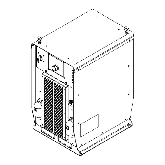
- Page 56 Hardware is common and not available unless listed. 20 21 802 955-A Figure 9-2. Windtunnel Assembly LH And RH OM-221 771 Page 52...
- Page 57 Item Dia. Part Mkgs. Description Quantity Figure 9-2. Windtunnel Assembly LH And RH (Fig 9-1 Item 6) ....214597 . . . Windtunnel, LH w/Components (including).
- Page 58 Hardware is common and not available unless listed. Ref. 802 916-B Figure 9-3. Top Tray Assembly Item Dia. Part Mkgs. Description Quantity Figure 9-3. Top Tray Assembly (Fig 9-1 Item 4) ..PC12 ..209676 .
- Page 59 Hardware is common and not available unless listed. 803 248-D Figure 9-4. Rear Panel Assembly Item Dia. Part Mkgs. Description Quantity Figure 9-4. Rear Panel Assembly (Fig 9-1 Item 8) ... . . 225597 .
- Page 60 Hardware is common and not available unless listed. Ref. 803 249-C Figure 9-5. Front Panel Assembly Item Dia. Part Mkgs. Description Quantity Figure 9-5. Front Panel Assembly (Fig 9-1 Item 14) ....207456 .
- Page 61 Item Dia. Part Mkgs. Description Quantity Figure 9-5. Front Panel Assembly (Fig 9-1 Item 14) (Continued) ....216966 . . . Cover, Connector D-sub 9 pin Male w/Chain .
- Page 62 Notes...
- Page 63 Effective January 1, 2007 (Equipment with a serial number preface of “LH” or newer) This limited warranty supersedes all previous Miller warranties and is exclusive with no other Warranty Questions? guarantees or warranties expressed or implied. LIMITED WARRANTY − Subject to the terms and conditions...
- Page 64 Contact the Delivering Carrier to: File a claim for loss or damage during shipment. For assistance in filing or settling claims, contact your distributor and/or equipment manufacturer’s Transportation Department. © PRINTED IN USA 2007 Miller Electric Mfg. Co. 2007−01...
Need help?
Do you have a question about the PipePro 450 RFC and is the answer not in the manual?
Questions and answers