Table of Contents
Troubleshooting

Related Manuals for Miller AXCESS 450 W/RMD


Summary of Contents for Miller AXCESS 450 W/RMD
- Page 1 OM-220 389M 2009−03 Processes MIG (GMAW) Welding Pulsed MIG (GMAW-P) Flux Cored (FCAW) Welding Description Arc Welding Power Source Axcess 450 Visit our website at File: Advanced Manufacturing Systems www.MillerWelds.com/ams...
- Page 2 We know you don’t have time to do it any other way. That’s why when Niels Miller first started building arc welders in 1929, he made sure his products offered long-lasting value and superior quality.
-
Page 3: Table Of Contents
TABLE OF CONTENTS SECTION 1 − SAFETY PRECAUTIONS - READ BEFORE USING ........1-1. - Page 4 TABLE OF CONTENTS SECTION 9 − TROUBLESHOOTING ............9-1.
- Page 5 DECLARATION OF CONFORMITY for European Community (CE marked) products. MILLER Electric Mfg. Co., 1635 Spencer Street, Appleton, WI 54914 U.S.A. declares that the product(s) identified in this declaration conform to the essential requirements and provisions of the stated Council Directive(s) and Standard(s).
-
Page 7: Section 1 − Safety Precautions - Read Before Using
SECTION 1 − SAFETY PRECAUTIONS - READ BEFORE USING som _2007−04 Protect yourself and others from injury — read and follow these precautions. 1-1. Symbol Usage DANGER! − Indicates a hazardous situation which, if Indicates special instructions. not avoided, will result in death or serious injury. The possible hazards are shown in the adjoining symbols or explained in the text. - Page 8 D Do not use welder to thaw frozen pipes. FUMES AND GASES can be hazardous. D Remove stick electrode from holder or cut off welding wire at contact tip when not in use. Welding produces fumes and gases. Breathing D Wear oil-free protective garments such as leather gloves, heavy these fumes and gases can be hazardous to your shirt, cuffless trousers, high shoes, and a cap.
-
Page 9: Additional Symbols For Installation, Operation, And Maintenance
1-3. Additional Symbols For Installation, Operation, And Maintenance FIRE OR EXPLOSION hazard. MOVING PARTS can cause injury. D Do not install or place unit on, over, or near D Keep away from moving parts such as fans. combustible surfaces. D Keep all doors, panels, covers, and guards D Do not install unit near flammables. -
Page 10: California Proposition 65 Warnings
1-4. California Proposition 65 Warnings For Gasoline Engines: Welding or cutting equipment produces fumes or gases which contain chemicals known to the State of California to Engine exhaust contains chemicals known to the State of cause birth defects and, in some cases, cancer. (California California to cause cancer, birth defects, or other reproduc- Health &... -
Page 11: Section 2 − Consignes De Sécurité − Lire Avant Utilisation
SECTION 2 − CONSIGNES DE SÉCURITÉ − LIRE AVANT UTILISATION fre_som_2007−04 Se protéger et protéger les autres contre le risque de blessure — lire et respecter ces consignes. 2-1. Symboles utilisés DANGER! − Indique une situation dangereuse qui si on Indique des instructions spécifiques. - Page 12 Il reste une TENSION DC NON NÉGLIGEABLE dans LE SOUDAGE peut provoquer un in les sources de soudage onduleur quand on a cendie ou une explosion. coupé l’alimentation. Le soudage effectué sur des conteneurs fermés tels D Arrêter les convertisseurs, débrancher le courant électrique et que des réservoirs, tambours ou des conduites peut décharger les condensateurs d’alimentation selon les instructions provoquer leur éclatement.
-
Page 13: Dangers Supplémentaires En Relation Avec L'installation, Le Fonctionnement Et La Maintenance
D Protéger les bouteilles de gaz comprimé d’une chaleur excessive, ACCUMULATIONS des chocs mécaniques, des dommages physiques, du laitier, des risquent de provoquer des blessures flammes ouvertes, des étincelles et des arcs. ou même la mort. D Placer les bouteilles debout en les fixant dans un support station- D Fermer l’alimentation du gaz protecteur en cas naire ou dans un porte-bouteilles pour les empêcher de tomber ou de non-utilisation. -
Page 14: Proposition Californienne 65 Avertissements
LES FILS DE SOUDAGE peuvent LE RAYONNEMENT HAUTE FRÉ- provoquer des blessures. QUENCE (H.F.) risque de provoquer des interférences. D Ne pas appuyer sur la gâchette avant d’en avoir reçu l’instruction. D Le rayonnement haute fréquence (H.F.) peut D Ne pas diriger le pistolet vers soi, d’autres per- provoquer des interférences avec les équipe- sonnes ou toute pièce mécanique en enga- ments de radio−navigation et de communica-... -
Page 15: Principales Normes De Sécurité
2-5. Principales normes de sécurité Safety in Welding, Cutting, and Allied Processes, ANSI Standard Z49.1, L4W 5NS (téléphone : 800-463-6727 ou à Toronto 416-747-4044, site de Global Engineering Documents (téléphone : 1-877-413-5184, site Internet : www.csa-international.org). Internet : www.global.ihs.com). Safe Practice For Occupational And Educational Eye And Face Protec- tion, ANSI Standard Z87.1, de American National Standards Institute, Recommended Safe Practices for the Preparation for Welding and Cut- 11 West 43rd Street, New York, NY 10036-8002 (téléphone :... - Page 16 OM-220 389 Page 10...
-
Page 17: Section 3 − Definitions
SECTION 3 − DEFINITIONS 3-1. Manufacturer’s Warning Label Definitions Warning! Watch Out! There are possible hazards as shown by the symbols. Electric shock from welding electrode or wiring can kill. 1.1 Wear dry insulating gloves. Do not touch electrode with bare hand. -
Page 18: Weee Label
> 5 min 219 844-A Warning! Watch Out! There are Do not touch fully charged can explode or cause other parts to possible hazards as shown by the capacitors. explode. symbols. Flying pieces of parts can cause Always wait 5 minutes after power is injury. -
Page 19: Symbols And Definitions
3-3. Symbols And Definitions Direct Current Alternating Amperage Voltage (DC) Current (AC) Output Circuit Breaker Remote Positive Negative Voltage Input Protective Earth Arc Force Constant Voltage Inductance (Ground) Three Phase Static Frequency Con- Gas Metal Arc Increase Line Connection verter- Welding (GMAW) Transformer- Rectifier... -
Page 20: Section 4 − Installation
SECTION 4 − NSTALLATION Appearance of actual unit may vary from unit shown in manual. 4-1. Serial Number And Rating Label Location The serial number and rating information for this product is located on the front panel. Use rating label to determine input power requirements and/or rated output. -
Page 21: Duty Cycle And Overheating
4-4. Duty Cycle And Overheating Duty Cycle is percentage of 10 minutes that unit can weld at rated load without overheating. If unit overheats, thermostat(s) opens, output stops, and cooling fan runs. Wait fifteen minutes for unit to cool. Reduce amperage or duty cycle before welding. -
Page 22: Selecting A Location
4-6. Selecting A Location Movement Tipping Do not move or operate unit where it could tip. Location Do not stack units. Beware of tipping. Special installation may be required where gasoline or volatile liquids are present − see NEC Article 511 or CEC Section 20. Lifting Forks Use lifting forks to move unit. -
Page 23: Rear Panel Receptacles And Supplementary Protectors
4-8. Rear Panel Receptacles And Supplementary Protectors 115 V 10 A AC Receptacle RC2 Receptacle supplies single-phase power. Maximum output from RC2 is limited by supplementary protector CB1 to 10 amps. Supplementary Protector CB1 Supplementary Protector CB2 CB1 protects 115 volt receptacle RC2 from overload. -
Page 24: Connecting To Weld Terminals
4-9. Connecting To Weld Terminals If using an electrode negative (straight polarity) process, the volt sense lead must be connected to the work. Do not place anything between weld cable terminal and copper bar. Tools Needed: 3/4 in (19mm) Correct Installation Incorrect Installation Ref. -
Page 25: Network Wire Feeder Receptacle Functions
4-10. Network Wire Feeder Receptacle Functions Pin* Pin Information Not used. Shield. Volt sense. Can low. Can high. +24 volts DC common. + 24 volts DC Motor voltage −40 volts Motor voltage +40 volts Ref. 803 417-A *The remaining pins are not used. 4-11. -
Page 26: Connecting Input Power
4-12. Connecting Input Power = GND/PE Earth Ground Route input conductors to filter board. Route ground conductor Kasjf;laksf;lkasdf'l;aksdf;lkasd;flksadflkasd;lk Kasjf;laksf;lkasdf'l;aksdf;lkasd;flksadflkasd;lk Kasjf;laksf;lkasdf'l;aksdf;lkasd;flksadflkasd;lk through tubing and cur- rent transducer to ground terminal. 219 842-A Tools Needed: 803 855-A / Ref. 803 766-A / 219 842-A 5/16 in applicable, use lugs of proper amperage Disconnect... -
Page 27: Section 5 − Recommended Setup Procedures
SECTION 5 − RECOMMENDED SETUP PROCEDURES 5-1. Selecting Weld Cable Sizes* ARC WELDING can cause Electromagnetic Interference. To reduce possible interference, keep weld cables as short as possible, close together, and down low, such as on the floor. Locate welding operation 100 meters from any sensitive electronic equipment. Be sure this welding machine is installed and grounded according to this manual. -
Page 28: Welding Circuit
5-2. Welding Circuit Minimizing the welding circuit loop can prevent extreme voltage drops that produce poor welding characteristics. Welding Power Source Electrode Cable Feeder Cable Work Cable Standard Welding Circuit Voltage Sensing Lead Wire Feeder Workpiece In pulse welding applications using inverter power sources,... -
Page 29: Arranging Welding Cables To Reduce Welding Circuit Inductance
5-3. Arranging Welding Cables To Reduce Welding Circuit Inductance Welding Power Source Electrode Cable Feeder Cable Work Cable Voltage Sensing Lead Wire Feeder Workpiece The method used to arrange cables has significant affect welding properties. As an example, Accupulse and RMD welding processes can produce high welding circuit inductance depending on cable... -
Page 30: Using Multiple Welding Power Sources
Welding on a single workpiece using multiple welding power sources can cause arc blow and arc impedance to develop or intensify. 5-4. Using Multiple Welding Power Sources Welding Power Source Electrode Cable Feeder Cable Work Cable Voltage Sensing Lead Wire Feeder Workpiece Each welding power source should have a separate work cable connection... -
Page 31: Voltage Sensing Lead And Work Cable Connections For Multiple Welding Arcs
5-5. Voltage Sensing Lead And Work Cable Connections For Multiple Welding Arcs A. Bad Setup Current Flow Path Ref. 804 460-A Welding Power Source Workpiece across the workpiece will not be measured correctly for the voltage feedback signal. Electrode Cable This arrangement is a bad setup due to Voltage feedback to the welding power Feeder Cable... - Page 32 B. Better Setup Current Flow Path Ref. 804 461-A Welding Power Source Wire Feeder the welding power sources. The most accurate voltage sensing may not be Electrode Cable Workpiece achieved due to voltage drops in the Feeder Cable workpiece. This require Work Cable This arrangement is a better setup for...
- Page 33 C. Best Setup Current Flow Path Ref. 804 462-A Welding Power Source Voltage Sensing Lead This arrangement is the best setup for proper voltage sensing at the workpiece. Electrode Cable Wire Feeder Voltage feedback to the welding power Feeder Cable sources will more accurate and result in Work Cable Workpiece...
-
Page 34: Section 6 − Operation
SECTION 6 − OPERATION 6-1. Front Panel Switches Ref. 803 418-B Power Switch Pilot Light PDA Port Light indicates status of welding power Turns unit On or Off. PC Port source, on when unit is on and off when unit is off. -
Page 35: Section 7 − Maintenance
SECTION 7 − MAINTENANCE 7-1. Routine Maintenance Maintain more often Disconnect power before maintaining. during severe conditions. n = Check Z = Change ~ = Clean l = Replace Reference * To be done by Factory Authorized Service Agent Every l Unreadable Labels ~ Weld Terminals l Damaged Gas Hose... -
Page 36: Section 8 − Safety Precautions For Servicing
SECTION 8 − SAFETY PRECAUTIONS FOR SERVICING Protect yourself and others from injury — read and follow these precautions. 8-1. Symbol Usage OM-220 389M - 2009−01, safety_stm 2007−04 DANGER! − Indicates a hazardous situation which, if Indicates special instructions. not avoided, will result in death or serious injury. The possible hazards are shown in the adjoining symbols or explained in the text. -
Page 37: California Proposition 65 Warnings
FALLING UNIT can cause injury. OVERUSE can cause OVERHEATING. D Allow cooling period; follow rated duty cycle. D Use lifting eye to lift unit only, NOT running gear, gas cylinders, or any other accessories. D Reduce current or reduce duty cycle before D Use equipment of adequate capacity to lift and starting to weld again. -
Page 38: Section 9 − Troubleshooting
SECTION 9 − TROUBLESHOOTING 9-1. Removing Cover and Measuring Input Capacitor Voltage Turn Off welding power source, and 900 Volts DC can be present on the capacitor bus disconnect input power. and significant DC voltage can remain on Remove cover capacitors after unit is Off. -
Page 39: Process Control Module Pc4 Diagnostic Led's
9-2. Process Control Module PC4 Diagnostic LED’s Process Control Module PC4 Diagnostic LED’s are visible inside unit, located on PC4 mounted on the top tray. Refer to Section 9-3 for information on diagnostic LED’s. Reinstall cover after checking diagnostic LED’s. LED1 LED2 LED3... -
Page 40: Network And Module Status Led's
9-4. Network And Module Status LED’s Network Status LED’s The following is a network status LED: LED4 on the PCM circuit board. Status Diagnosis The circuit board is not on-line with the network or there is no power applied to the circuit board. Green The circuit board is operating normally and the on-line connection is made with the network. -
Page 41: Troubleshooting
9-5. Troubleshooting Trouble Remedy No weld output; completely inoperative Place line disconnect in On position (see Section 4-12). Check and replace line fuse(s), if necessary, or reset circuit breaker (see Section 4-12). Check for proper input power connections (see Section 4-12). No weld output;... -
Page 42: Section 10 − Electrical Diagrams
SECTION 10 − ELECTRICAL DIAGRAMS Figure 10-1. Circuit Diagram For Welding Power Source OM-220 389 Page 36... - Page 43 220 420-C OM-220 389 Page 37...
-
Page 44: Section 11 − Parts List
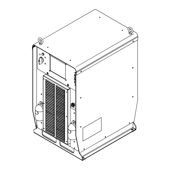
SECTION 11 − PARTS LIST Hardware is common and not available unless listed. 4 − Fig 11-3 5 − Fig 11-2 8 − Fig 11-4 16 − Fig 11-5 Ref. 803 856-B Figure 11-1. Main Assembly OM-220 389 Page 38... - Page 45 Item Dia. Part Mkgs. Description Quantity Figure 11-1. Main Assembly ....210492 . . . Cover, Top ........... .
- Page 46 Item Dia. Part Mkgs. Description Quantity Figure 11-2. Windtunnel Assembly LH And RH (Fig 11-1 Item 6) ....214597 . . . Windtunnel, LH w/Components (including).
- Page 47 Hardware is common and not available unless listed. 803 422-B Figure 11-3. Top Tray Assembly Item Dia. Part Mkgs. Description Quantity Figure 11-3. Top Tray Assembly (Fig 11-1 Item 4) ... . . 239598 .
- Page 48 Hardware is common and not available unless listed. 803 423-C Figure 11-4. Rear Panel Assembly Item Dia. Part Mkgs. Description Quantity Figure 11-4. Rear Panel Assembly (Fig 11-1 Item 8) ....210474 .
- Page 49 Hardware is common and not available unless listed. Ref. 803 424-B Figure 11-5. Front Panel Assembly Item Dia. Part Mkgs. Description Quantity Figure 11-5. Front Panel Assembly (Fig 11-1 Item 14) ....207456 .
- Page 50 Item Dia. Part Mkgs. Description Quantity Figure 11-5. Front Panel Assembly (Continued) ....207896 . . . Box, Louver ...........
- Page 51 Effective January 1, 2009 (Equipment with a serial number preface of LK or newer) This limited warranty supersedes all previous Miller warranties and is exclusive with no other Warranty Questions? guarantees or warranties expressed or implied. LIMITED WARRANTY − Subject to the terms and conditions...
- Page 52 Contact the Delivering Carrier to: File a claim for loss or damage during shipment. For assistance in filing or settling claims, contact your distributor and/or equipment manufacturer’s Transportation Department. © ORIGINAL INSTRUCTIONS − PRINTED IN USA 2009 Miller Electric Mfg. Co. 2009−01...
Need help?
Do you have a question about the AXCESS 450 W/RMD and is the answer not in the manual?
Questions and answers