
Related Manuals for Miller INFINITY 35


Summary of Contents for Miller INFINITY 35
- Page 1 OM-206360 C 2006−07 Effective with serial number: 217 769 Processes MIG (GMAW) Welding Flux Cored (FCAW) Description INFINITY 35/45 OWNER’S MANUAL www.MillerWelds.com...
- Page 2 From Miller to You Thank you and congratulations on choosing Miller. Now you can get the job done and get it done right. We know you don’t have time to do it any other way. That’s why when Niels Miller first started building arc welders in 1929, he made sure his products offered long-lasting value and superior quality.
-
Page 3: Table Of Contents
TABLE OF CONTENTS SECTION 1 − SAFETY PRECAUTIONS - READ BEFORE USING ........1-1. - Page 4 Phone: 39(02)98290-1 20098 San Giuliano Milanese, Italy Phone: 39(02)98290-1 Fax: 39(02)98290203 European Contact Signature: INFINITY 35/45 Declares that this product: conforms to the following Directives and Standards: Directives Low Voltage: 73/23/EEC Machinery Directives: 89/392/EEC And their amendments 91/368/EEC, 93/C, 133/04, 93/68/EEC...
-
Page 5: Section 1 − Safety Precautions - Read Before Using
SECTION 1 − SAFETY PRECAUTIONS - READ BEFORE USING som _3/05 Y Warning: Protect yourself and others from injury — read and follow these precautions. 1-1. Symbol Usage Means Warning! Watch Out! There are possible hazards with this procedure! The possible hazards are shown in the adjoining symbols. - Page 6 ARC RAYS can burn eyes and skin. BUILDUP OF GAS can injure or kill. D Shut off shielding gas supply when not in use. Arc rays from the welding process produce intense visible and invisible (ultraviolet and infrared) rays D Always ventilate confined spaces or use that can burn eyes and skin.
-
Page 7: Additional Symbols For Installation, Operation, And Maintenance
D Read Owner’s Manual before using or servic- support unit. ing unit. D If using lift forks to move unit, be sure forks are D Use only genuine Miller/Hobart replacement long enough to extend beyond opposite side of parts. unit. -
Page 8: Principal Safety Standards
1-5. Principal Safety Standards Safety in Welding, Cutting, and Allied Processes, ANSI Standard Z49.1, Boulevard, Rexdale, Ontario, Canada (phone: from Global Engineering Documents (phone: 1-877-413-5184, website: 800−463−6727 or in Toronto 416−747−4044, website: www.csa−in- www.global.ihs.com). ternational.org). Practice For Occupational And Educational Eye And Face Protection, Recommended Safe Practices for the Preparation for Welding and Cut- ANSI Standard Z87.1, from American National Standards Institute, 11 ting of Containers and Piping, American Welding Society Standard... -
Page 9: Section 2 − Definitions
− SECTION 2 DEFINITIONS 2-1. Warning Label Definitions Warning! Watch Out! There are possible 2.1 Keep your head out of the fumes. Arc rays can burn eyes and injure hazards as shown by the symbols. skin. 2.2 Use forced ventilation or local exhaust to remove the fumes. - Page 10 Warning! Watch Out! There are possible hazards as shown by the symbols. Electric shock from wiring can kill. Disconnect input plug or power before working on machine. Read the Owner’s Manual before working on this machine. Consult rating label for input power requirements, and check power available at the job site −...
-
Page 11: Manufacturer's Rating Labels For Ce Products
2-2. Manufacturer’s Rating Labels For CE Products MADE IN ITALY MADE IN ITALY INFINITY 35 COD. 029015365 INFINITY 45 COD. 029015360 EN 60974 − 1 EN 60974 − 1 8A − 15V 15A − 15V 350A − 31.5V 450A − 36.5 V... -
Page 12: Duty Cycle And Overheating
Duty Cycle is percentage of 10 min- utes that unit can weld at rated load without overheating. If unit overheats, thermostat(s) INFINITY 45 INFINITY 35 opens, output stops, and cooling fan runs. Wait fifteen minutes for Rated Output Rated Output unit to cool. -
Page 13: Weld Output Terminals And Selecting Cable Sizes
2-6. Weld Output Terminals And Selecting Cable Sizes Y ARC WELDING can cause Electromagnetic Interference. To reduce possible interference, keep weld cables as short as possible, close together, and down low, such as on the floor. Locate welding operation 100 meters from any sensitive electronic equipment. Be sure this welding machine is installed and grounded according to this manual. -
Page 14: Section 3 − Installation
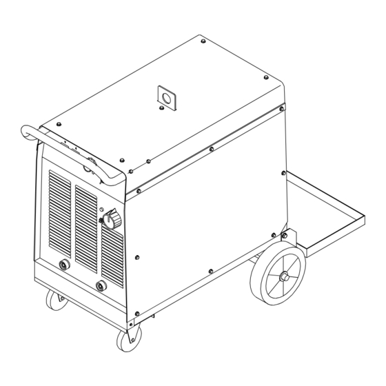
SECTION 3 − INSTALLATION 3-1. Selecting A Location Lifting Eye Lifting Forks Use lifting eye or lifting forks to move unit. Movement If using lifting forks, extend forks beyond opposite side of unit. Position unit so air can circulate. 500 mm 500 mm 500 mm OM-206 360 Page 10... -
Page 15: Typical Mig Connections
3-2. Typical MIG Connections Power source Work clamp (connect to re- ceptacle as shown) Water cooler for torch Cylinder (chain to running gear) Cylinder valve Open valve slightly so gas flow blows dirt from valve. Close valve. Regulator/Flow gauge Install so face is vertical Flow adjust Gas supply line Wire feeder... -
Page 16: Positioning Jumper Links
All these units are connected on 400 V. 230V 400V 400V 3-5. Electrical Service Guide Infinity 35 Infinity 45 Input Voltage Input amperes at rated output Fuse or circuit breaker rating (max. rec) Input conductor size* 6 mm 6 mm... -
Page 17: Connecting Input Power
3-6. Connecting Input Power ST-161 454-A GND/PE Y Have only qualified persons make this installation. Y Special installation may be required where gasoline or volatile liquids are present − consult national or local reg- ulations. GND/PE Connect first. Tools Needed: 3-7. -
Page 18: Control Panel
3-8. Control Panel High temperature shutdown light This lights up when unit overheats and shuts down. Indicator Lamp This lights up when the power switch is placed in the ON position. Power switch − ON/OFF Circuit breaker This circuit protects the auxiliary power High inductance negative out- put terminal... -
Page 19: Section 4 − Maintenance And Troubleshooting
SECTION 4 − MAINTENANCE AND TROUBLESHOOTING 4-1. Routine Maintenance Y Disconnect power before maintaining. 3 Months Replace Repair or Clean and unreadable replace tighten weld labels. cracked weld terminals. cable. 6 Months Blow out or vacuum inside. During heavy service, clean monthly. 4-2. - Page 20 Notes OM-206 360 Page 16...
-
Page 21: Section 5 - Electrical Diagram
SECTION 5 - ELECTRICAL DIAGRAM ACCENDITORE cod.956 142 398 Revised 11/26 OM-206 360 Page 17... -
Page 22: Section 6 - Parts List
SECTION 6 - PARTS LIST 6-1. Main Assembly − Infinity 35/45 OM-206 360 Page 18... - Page 23 Item Ref. Code Item Ref. Code 116121119 XH.0.0.3 156006030 XH.0.0.6 156002044 XH.0.0.20 230/400 058021130 XK.4 000006393 QA.0.0.10 028021449 XH.10 Fiancata SX 116122278 VS.0.0.6 con terz. 027015573 XK.1.1 230/400 Fiancata DX 116122277 VS.0.0.5 senza terz. 027015574 XK.1.2 PC.1 058061050 XH.7 230/400 057095011 ZR.0.11 027015572 XH.8.1 PC.2...
- Page 24 Notes...
- Page 25 Notes...
- Page 26 Notes...
- Page 27 Effective January 1, 2006 This limited warranty supersedes all previous Miller warranties and is exclusive with no other guarantees or warranties expressed or implied. LIMITED WARRANTY − Subject to the terms and conditions APT Model Plasma Cutting Torches below, ITW Welding Products Italy S.r.l., warrants to its...
- Page 28 File a claim for loss or damage during Phone: 39 (0) 2982901 Fax: 39 (0) 298290-203 shipment. email: miller@itw−welding.it For assistance in filing or settling claims, contact your distributor and/or equipment manufacturer’s Transportation Department. © PRINTED IN USA 2006 Miller Electric Mfg. Co. 1/06...
Need help?
Do you have a question about the INFINITY 35 and is the answer not in the manual?
Questions and answers