Tektronix Keithley SourceMeter 2470 User Manual
High voltage instrument
Hide thumbs
Also See for Keithley SourceMeter 2470:
- Reference manual (1125 pages) ,
- User manual (68 pages) ,
- Quick start manual (25 pages)

Related Manuals for Tektronix Keithley SourceMeter 2470


Summary of Contents for Tektronix Keithley SourceMeter 2470
- Page 1 Model 2470 ® High Voltage SourceMeter Instrument User’s Manual 2470-900-01 Rev. B / August 2019 99 Washington Street Melrose, MA 02176 Phone 781-665-1400 Toll Free 1-800-517-8431 Visit us at www.TestEquipmentDepot.com...
- Page 2 Model 2470 High Voltage SourceMeter Instrument User's Manual...
- Page 3 © 2019, Keithley Instruments, LLC Cleveland, Ohio, U.S.A. All rights reserved. Any unauthorized reproduction, photocopy, or use of the information herein, in whole or in part, without the prior written approval of Keithley Instruments, LLC, is strictly prohibited. These are the original instructions in English. ®...
- Page 4 Safety precautions The following safety precautions should be observed before using this product and any associated instrumentation. Although some instruments and accessories would normally be used with nonhazardous voltages, there are situations where hazardous conditions may be present. This product is intended for use by personnel who recognize shock hazards and are familiar with the safety precautions required to avoid possible injury.
- Page 5 For safety, instruments and accessories must be used in accordance with the operating instructions. If the instruments or accessories are used in a manner not specified in the operating instructions, the protection provided by the equipment may be impaired. Do not exceed the maximum signal levels of the instruments and accessories. Maximum signal levels are defined in the specifications and operating information and shown on the instrument panels, test fixture panels, and switching cards.
-
Page 6: Table Of Contents
Table of contents Introduction ........................ 1-1 Welcome ..........................1-1 Introduction to this manual ....................1-2 Extended warranty ....................... 1-2 Contact information ......................1-2 Organization of manual sections ..................1-3 Applications .......................... 1-3 Front-panel overview ....................2-1 Power the instrument on or off ..................... 2-1 Front-panel overview ...................... - Page 7 Table of contents Model 2470 High Voltage SourceMeter Instrument User's Manual Making basic front-panel measurements ..............4-1 Introduction .......................... 4-1 Equipment required for this application ................4-2 Device connections ......................4-2 Make front-panel measurements ..................4-3 How to make front-panel measurements .................. 4-3 Leakage current and insulation resistance .............
- Page 8 Model 2470 High Voltage SourceMeter Instrument User's Manual Table of contents Where can I find updated drivers? ..................7-1 How do I upgrade the firmware? ..................7-2 Why can't the 2470 read my USB flash drive? ..............7-3 How do I change the command set? ................... 7-3 Why am I getting a 5074 event code? .................
-
Page 9: Introduction
Section 1 Introduction In this section: Welcome .................. 1-1 Introduction to this manual ............1-2 Extended warranty ..............1-2 Contact information ..............1-2 Organization of manual sections ..........1-3 Applications ................1-3 Welcome Thank you for choosing a Keithley Instruments product. The 2470 High Voltage SourceMeter Instrument is a precise, low-noise instrument that combines a stable DC power supply with a repeatable, high-impedance multimeter. -
Page 10: Introduction To This Manual
Section 1: Introduction Model 2470 High Voltage SourceMeter Instrument User's Manual Introduction to this manual This manual provides detailed applications to help you achieve success with your Keithley Instruments 2470. This manual also provides information about the basics of the front panel to familiarize you with the instrument. -
Page 11: Organization Of Manual Sections
Model 2470 High Voltage SourceMeter Instrument User's Manual Section 1: Introduction Organization of manual sections This manual is organized into the following sections: • Front-panel overview (on page 2-1): Describes the basics of using the front-panel interface. • Using a remote interface (on page 3-1): Describes the basics of remote communications and using the instrument web interface. -
Page 12: Front-Panel Overview
Section 2 Front-panel overview In this section: Power the instrument on or off ..........2-1 Front-panel overview ..............2-3 Turn the 2470 output on or off ..........2-4 Touchscreen display ..............2-5 Store measurements on a USB flash drive ......2-10 Save screen captures to a USB flash drive ...... - Page 13 Section 2: Front-panel overview Model 2470 High Voltage SourceMeter Instrument User's Manual To connect the power cord: 1. Make sure that the front-panel POWER switch is in the off (O) position. 2. Connect the female end of the supplied power cord to the AC receptacle on the rear panel. 3.
-
Page 14: Front-Panel Overview
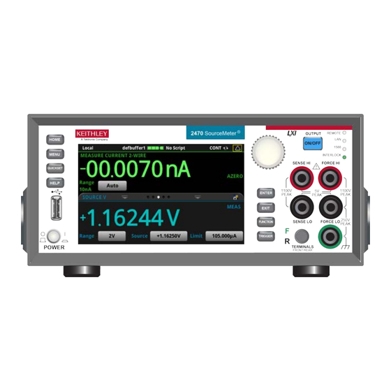
Model 2470 High Voltage SourceMeter Instrument User's Manual Section 2: Front-panel overview Front-panel overview The front panel of the 2470 is shown below. Descriptions of the controls on the front panel follow the figure. Figure 2: Model 2470 front panel Control Graphic Description... -
Page 15: Turn The 2470 Output On Or Off
Section 2: Front-panel overview Model 2470 High Voltage SourceMeter Instrument User's Manual Control Graphic Description Returns to the previous screen or closes a dialog box. For example, EXIT key press the EXIT key when the main menu is displayed to return to the home screen. -
Page 16: Touchscreen Display
Model 2470 High Voltage SourceMeter Instrument User's Manual Section 2: Front-panel overview When the source of the instrument is turned off, it may not completely isolate the instrument from the external circuit. You can use the Output Off setting to place the 2470 in a known, noninteractive state during idle periods, such as when you are changing the device under test. -
Page 17: Select Items On The Touchscreen
Section 2: Front-panel overview Model 2470 High Voltage SourceMeter Instrument User's Manual Select items on the touchscreen To select an item on the displayed screen, do one of the following: • Touch it with your finger • Turn the navigation control to highlight the item, and then press the navigation control to select it The following topics describe the 2470 touchscreen in more detail. - Page 18 Model 2470 High Voltage SourceMeter Instrument User's Manual Section 2: Front-panel overview Swipe screen heading bar The heading bar of the swipe screen contains the following options. Figure 4: Swipe screens, maximized and minimized Screen element Description Minimize indicator You can swipe down to minimize the swipe screens. Swipe screen indicator Each circle represents one swipe screen.
- Page 19 Section 2: Front-panel overview Model 2470 High Voltage SourceMeter Instrument User's Manual SOURCE swipe screen The SOURCE swipe screen shows the present value of the source and the set values for source, source range, and source limit. You can change the set values from the front panel by selecting the buttons on this screen.
- Page 20 Model 2470 High Voltage SourceMeter Instrument User's Manual Section 2: Front-panel overview STATISTICS swipe screen The STATISTICS swipe screen contains information about the readings in the active reading buffer. When the reading buffer is configured to fill continuously and overwrite old data with new data, the buffer statistics include the data that was overwritten.
-
Page 21: Menu Overview
Section 2: Front-panel overview Model 2470 High Voltage SourceMeter Instrument User's Manual Menu overview To access the main menu, press the MENU key on the 2470 front panel. The figure below shows the organization of the main menu. Figure 10: 2470 main menu The main menu includes submenus that are labeled in green across the top of the display. -
Page 22: Save Screen Captures To A Usb Flash Drive
Model 2470 High Voltage SourceMeter Instrument User's Manual Section 2: Front-panel overview Save screen captures to a USB flash drive You can save a screen capture of the front-panel display to a graphic file on a USB flash drive. The instrument saves the graphic file in PNG file format. -
Page 23: Using A Remote Interface
Section 3 Using a remote interface In this section: Remote communications interfaces ......... 3-1 Supported remote interfaces ............ 3-1 GPIB communications .............. 3-2 LAN communications ............... 3-4 USB communications ............... 3-7 Using the web interface ............3-12 Determine the command set to use ........3-15 Remote communications interfaces You can choose from one of several communication interfaces to send commands to and receive responses from the 2470. -
Page 24: Gpib Communications
Section 3: Using a remote interface Model 2470 High Voltage SourceMeter Instrument User's Manual GPIB communications The 2470 GPIB interface is IEEE Std 488.1 compliant and supports IEEE Std 488.2 common commands and status model topology. You can have up to 15 devices connected to a GPIB interface, including the controller. The maximum cable length is the lesser of either: •... - Page 25 Model 2470 High Voltage SourceMeter Instrument User's Manual Section 3: Using a remote interface To allow many parallel connections to one instrument, stack the connectors. Each connector has two screws on it to ensure that connections remain secure. The figure below shows a typical connection diagram for a test system with multiple instruments.
-
Page 26: Set The Gpib Address
Section 3: Using a remote interface Model 2470 High Voltage SourceMeter Instrument User's Manual Set the GPIB address The default GPIB address is 18. You can set the address from 1 to 30 if it is unique in the system. This address cannot conflict with an address that is assigned to another instrument or to the GPIB controller. -
Page 27: Set Up Lan Communications On The Instrument
Model 2470 High Voltage SourceMeter Instrument User's Manual Section 3: Using a remote interface Contact your network administrator to confirm your specific network requirements before setting up a LAN connection. If you have problems setting up the LAN, refer to LAN troubleshooting suggestions (on page 3-13). -
Page 28: Set Up Lan Communications On The Computer
Section 3: Using a remote interface Model 2470 High Voltage SourceMeter Instrument User's Manual Set up manual LAN configuration If necessary, you can set the IP address on the instrument manually. You can also enable or disable the DNS settings and assign a host name to the DNS server. Contact your corporate information technology (IT) department to secure a valid IP address for the instrument when placing the instrument on a corporate network. -
Page 29: Usb Communications
Model 2470 High Voltage SourceMeter Instrument User's Manual Section 3: Using a remote interface Verify the LAN connection on the 2470 Make sure that your 2470 is connected to the network by confirming that your instrument was assigned an IP address. To verify the LAN connection: 1. -
Page 30: Connect A Computer To The 2470 Using Usb
Section 3: Using a remote interface Model 2470 High Voltage SourceMeter Instrument User's Manual Connect a computer to the 2470 using USB To communicate from a computer to the instrument you need a USB cable with a USB Type B connector end and a USB type A connector end. - Page 31 Model 2470 High Voltage SourceMeter Instrument User's Manual Section 3: Using a remote interface To use the Keithley Configuration Panel to determine the VISA resource string: 1. Click Start > Keithley Instruments > Keithley Configuration Panel. The Select Operation dialog box is displayed. Figure 13: Select Operation dialog box 2.
- Page 32 Section 3: Using a remote interface Model 2470 High Voltage SourceMeter Instrument User's Manual 4. Select USB. 5. Click Next. The Select Instrument Driver dialog box is displayed. Figure 15: Select Instrument Driver dialog box 6. Select Auto-detect Instrument Driver - Model. 7.
- Page 33 Model 2470 High Voltage SourceMeter Instrument User's Manual Section 3: Using a remote interface 9. In the Virtual Instrument Name box, enter a name that you want to use to refer to the instrument. 10. Select Finish. 11. Select Cancel to close the Wizard. 12.
-
Page 34: Using The Web Interface
Section 3: Using a remote interface Model 2470 High Voltage SourceMeter Instrument User's Manual Using the web interface The 2470 web interface allows you to make settings and control your instrument through a web page. The web page includes: • Instrument status. -
Page 35: Lan Troubleshooting Suggestions
Model 2470 High Voltage SourceMeter Instrument User's Manual Section 3: Using a remote interface LAN troubleshooting suggestions If you are unable to connect to the web interface of the instrument, check the following items: • The network cable is in the LAN port on the rear panel of the instrument, not one of the ®... -
Page 36: Web Interface Home Page
Section 3: Using a remote interface Model 2470 High Voltage SourceMeter Instrument User's Manual Web interface Home page Figure 18: 2470 web interface Home page The Home page of the instrument provides information about the instrument. It includes: • The instrument model number, manufacturer, serial number, and firmware revision number. •... -
Page 37: Review Events In The Event Log
Model 2470 High Voltage SourceMeter Instrument User's Manual Section 3: Using a remote interface Review events in the event log Under LXI Home, the Log option opens the event log. The event log records all LXI events that the instrument generates and receives. The log includes the following information: •... - Page 38 Section 3: Using a remote interface Model 2470 High Voltage SourceMeter Instrument User's Manual To change to the SCPI command set from a remote interface: Send the command: *LANG SCPI Reboot the instrument. To change to the TSP command set from a remote interface: Send the command: *LANG TSP Reboot the instrument.
-
Page 39: Making Basic Front-Panel Measurements
Section 4 Making basic front-panel measurements In this section: Introduction ................4-1 Equipment required for this application ........4-2 Device connections ..............4-2 Make front-panel measurements ..........4-3 Introduction You can use the 2470 to source voltage or current and make measurements from the front panel. Make sure you select functions before you make changes to other instrument settings. -
Page 40: Equipment Required For This Application
Section 4: Making basic front-panel measurements Model 2470 High Voltage SourceMeter Instrument User's Manual Equipment required for this application Equipment required for this application: • 2470 High Voltage SourceMeter Instrument • Two insulated banana cables; you can use the set that is provided with the 2470, the Keithley Instruments Model 8608 High-Performance Clip Lead Set •... -
Page 41: Make Front-Panel Measurements
Model 2470 High Voltage SourceMeter Instrument User's Manual Section 4: Making basic front-panel measurements Make front-panel measurements For this application, you will: • Select the source and measure functions • Select the source range • Set the source value • Set the source limit •... -
Page 43: Leakage Current And Insulation Resistance
Section 5 Leakage current and insulation resistance In this section: Introduction ................5-1 Equipment required ..............5-2 Set up remote communications ..........5-2 Device connections ..............5-2 Measuring leakage current ............5-4 Measuring insulation resistance ..........5-9 Introduction Tests to measure the leakage current or insulation resistance of a device are very similar. In both cases, you can apply a fixed bias voltage and measure the resulting current. -
Page 44: Equipment Required
Section 5: Leakage current and insulation resistance Model 2470 High Voltage SourceMeter Instrument User's Manual Equipment required • One 2470 High Voltage SourceMeter Instrument • Two TRX-1100V-X 3-Slot High-Voltage Low-Noise Triaxial Cables (available from Keithley Instruments) • One high-voltage capacitor for the leakage current application •... - Page 45 Model 2470 High Voltage SourceMeter Instrument User's Manual Section 5: Leakage current and insulation resistance The following figure shows schematic diagrams. One shows measuring the leakage current of a capacitor. The other shows measuring the insulator resistance between two conductors of a coaxial cable.
-
Page 46: Measuring Leakage Current
Section 5: Leakage current and insulation resistance Model 2470 High Voltage SourceMeter Instrument User's Manual Figure 23: Rear-panel connections insulation resistance test Measuring leakage current The following application demonstrates how to use the 2470 to measure the leakage current of a high-voltage 10 µF capacitor by sourcing a voltage and measuring the resulting current using the front panel or over the remote interface. -
Page 47: Set Up The Leakage Current Application Using The Front Panel
Model 2470 High Voltage SourceMeter Instrument User's Manual Section 5: Leakage current and insulation resistance When you use the 2470 to measure small current values, ensure that the device under test is electrostatically shielded. If the capacitor rating is greater than 20 nF, enable the high capacitance mode for best results. -
Page 48: View The Measurements On The Front-Panel Graph
Section 5: Leakage current and insulation resistance Model 2470 High Voltage SourceMeter Instrument User's Manual View the measurements on the front-panel graph To view the leakage current measurements on the front-panel graph: 1. Press the MENU key. 2. Under Views, select Graph. 3. -
Page 49: Set Up The Leakage Current Application Using Scpi Commands
Model 2470 High Voltage SourceMeter Instrument User's Manual Section 5: Leakage current and insulation resistance Set up the leakage current application using SCPI commands The following SCPI code performs a capacitor leakage measurement by sourcing 300 V and measuring the resulting leakage current. The DurationLoop trigger model template applies the voltage for 30 seconds and makes measurements at 200 ms intervals. - Page 50 Section 5: Leakage current and insulation resistance Model 2470 High Voltage SourceMeter Instrument User's Manual To enable TSP commands: 1. Press the MENU key. 2. Under System, select Settings. 3. Set the Command Set to TSP. 4. At the prompt to reboot, select Yes. The following TSP code performs a capacitor leakage measurement by sourcing 300 V and measuring the resulting leakage current.
-
Page 51: Measuring Insulation Resistance
Model 2470 High Voltage SourceMeter Instrument User's Manual Section 5: Leakage current and insulation resistance The graph in the following figure shows the results of this application. Notice the exponential current response of the capacitor as it charges up to 300 V over time. Figure 25: Leakage current test results Measuring insulation resistance The following application demonstrates how to use the 2470 to measure insulator resistance. -
Page 52: Set Up The Insulation Resistance Application Using The Front Panel
Section 5: Leakage current and insulation resistance Model 2470 High Voltage SourceMeter Instrument User's Manual Set up the insulation resistance application using the front panel To set up the application from the front panel: 1. Connect the device under test (DUT) to the rear panel of the 2470, as described in Devi ce connections (on page 5-2). -
Page 53: Viewing The Measurements On The Front-Panel Graph
Model 2470 High Voltage SourceMeter Instrument User's Manual Section 5: Leakage current and insulation resistance Viewing the measurements on the front-panel graph To view the insulation resistance measurements on the front-panel graph: 1. Press the MENU key. 2. Under Views, select Graph. The following figure shows the front-panel graph for this application. -
Page 54: Set Up The Application Using Scpi Commands
Section 5: Leakage current and insulation resistance Model 2470 High Voltage SourceMeter Instrument User's Manual Set up the application using SCPI commands The following SCPI commands make insulation resistance measurements by sourcing 700 V and measuring the resistance. The Simple Loop trigger model template is used to make 10 measurements at 100 ms intervals. - Page 55 Model 2470 High Voltage SourceMeter Instrument User's Manual Section 5: Leakage current and insulation resistance The following TSP commands make insulation resistance measurements by sourcing 700 V and measuring the resistance. The Simple Loop trigger model template is used to make 10 measurements at 100 ms intervals.
- Page 56 Section 5: Leakage current and insulation resistance Model 2470 High Voltage SourceMeter Instrument User's Manual The graph in the following figure demonstrates what the plotted results might look like. Figure 27: Insulation resistance test results 5-14 2470-900-01 Rev. B / August 2019...
-
Page 57: Measure I-V Characteristics Of Fets
Section 6 Measure I-V characteristics of FETs In this section: Introduction ................6-1 Equipment required ..............6-2 Set up remote communications ..........6-2 Set up external hardware triggers ..........6-3 Device connections ..............6-5 Remote control of FET testing using SCPI commands .... 6-8 Remote control of FET testing using TSP commands .... -
Page 58: Equipment Required
Section 6: Measure I-V characteristics of FETs Model 2470 High Voltage SourceMeter Instrument User's Manual The SCPI and TSP examples differ in this application. The TSP version uses Keithley Instruments ® TSP-Link , which is a high-speed trigger synchronization and communication bus that test system builders can use to connect multiple instruments in a master and subordinate configuration. -
Page 59: Set Up External Hardware Triggers
Model 2470 High Voltage SourceMeter Instrument User's Manual Section 6: Measure I-V characteristics of FETs Set up external hardware triggers To enable synchronization between the two 2470 instruments for stepping and sweeping voltages, connect the external triggers of each instrument to the other. The cabling you use depends on which 2470 programming command set you choose to control the test. -
Page 60: Connections For The Tsp Command Set
Section 6: Measure I-V characteristics of FETs Model 2470 High Voltage SourceMeter Instrument User's Manual If you are using USB cables to connect the computer and 2470 instruments, each instrument must be connected to the computer with a separate USB cable. If you are using ethernet connections to connect the computer and 2470 instruments, the instruments and computer must be connected using an ethernet switch or hub. -
Page 61: Device Connections
Model 2470 High Voltage SourceMeter Instrument User's Manual Section 6: Measure I-V characteristics of FETs To set the 2470 TSP-Link nodes from the front panel: 1. Press the MENU key. 2. Under System, select Communication. The SYSTEM COMMUNICATION window opens. 3. - Page 62 Section 6: Measure I-V characteristics of FETs Model 2470 High Voltage SourceMeter Instrument User's Manual Figure 31: Drain leakage current measurement device connections The following figure shows the connections from the rear-panel terminals of the 2470. Figure 32: Drain leakage current measurement rear-panel terminal connections 2470-900-01 Rev.
-
Page 63: Subthreshold Current Or Drain Family Of Curves Measurement Device Connections
Model 2470 High Voltage SourceMeter Instrument User's Manual Section 6: Measure I-V characteristics of FETs Subthreshold current or drain family of curves measurement device connections Both a subthreshold current and a drain family of curves measurement use the same instrument connections. -
Page 64: Remote Control Of Fet Testing Using Scpi Commands
Section 6: Measure I-V characteristics of FETs Model 2470 High Voltage SourceMeter Instrument User's Manual The following figure shows the connections from the rear-panel terminals of both 2470s to the FET. Figure 34: Two 2470s set up to test a three-terminal FET Remote control of FET testing using SCPI commands The two example sequences of SCPI commands for this application generate a drain family of curves on a FET using two 2470 instruments. - Page 65 Model 2470 High Voltage SourceMeter Instrument User's Manual Section 6: Measure I-V characteristics of FETs Send the following commands for this example application: SMU 1, Commands Description SMU 2, or pseudocode SMU 1 *RST Reset the instrument. :SENS:FUNC "CURR" ...
- Page 66 Section 6: Measure I-V characteristics of FETs Model 2470 High Voltage SourceMeter Instrument User's Manual SMU 2 *RST Reset the instrument. :SENS:FUNC "CURR" Set to measure current. :SENS:CURR:RANG:AUTO ON :ROUT:TERM REAR Set to measure with autorange enabled. :SOUR:FUNC VOLT ...
-
Page 67: Set Up The Application Using Scpi Commands In A Linear Sweep
Model 2470 High Voltage SourceMeter Instrument User's Manual Section 6: Measure I-V characteristics of FETs SMU 2 :INIT Initiate the trigger model. *WAI Wait for the model to complete. Pseudocode vds = [] Create an empty array to hold ids = [] measured voltage values. - Page 68 Section 6: Measure I-V characteristics of FETs Model 2470 High Voltage SourceMeter Instrument User's Manual SMU 1, Commands Description SMU 2, or pseudocode SMU 1 *RST Reset the instrument. :SENS:FUNC "CURR" Set to measure current. :SENS:CURR:RANG:AUTO ON :ROUT:TERM REAR Set to measure with autorange :SOUR:FUNC VOLT...
-
Page 69: Remote Control Of Fet Testing Using Tsp Commands
Model 2470 High Voltage SourceMeter Instrument User's Manual Section 6: Measure I-V characteristics of FETs Remote control of FET testing using TSP commands The following TSP code is designed to be run from Keithley Instruments Test Script Builder (TSB). You can install and use TSB to write code and develop scripts for TSP-enabled instruments. Information about how to use TSB is in the online help for TSB and in the “Introduction to TSP operation”... -
Page 70: Set Up A Subthreshold Current Measurement Using Tsp Commands
Section 6: Measure I-V characteristics of FETs Model 2470 High Voltage SourceMeter Instrument User's Manual -- Parse index and data into three columns. print("Rdg #, Time (s), Current (A)") for i = 1, defbuffer1.n do print(string.format("%i, %.5f, %.6e", i, defbuffer1.relativetimestamps[i], defbuffer1[i])) The graph in the following figure demonstrates what the plotted drain leakage current might look like. - Page 71 Model 2470 High Voltage SourceMeter Instrument User's Manual Section 6: Measure I-V characteristics of FETs Send the following commands for this example application: --######################## Settings and TSP-Link setup ################ local gateVstart = 0 local gateVstop = 5 local gateStepSize = 0.1 local gateIlimit = 0.1 local drainV = 10 local drainIlimit = 0.1...
- Page 72 Section 6: Measure I-V characteristics of FETs Model 2470 High Voltage SourceMeter Instrument User's Manual local stepPoints = (gateVstop - gateVstart) * (1 / gateStepSize) + 1 -- Set up the trigger model. gate.trigger.model.setblock(1, gate.trigger.BLOCK_CONFIG_RECALL, "stepVals") gate.trigger.model.setblock(2, gate.trigger.BLOCK_SOURCE_OUTPUT, gate.smu.ON) gate.trigger.model.setblock(3, gate.trigger.BLOCK_MEASURE_DIGITIZE) gate.trigger.model.setblock(4, gate.trigger.BLOCK_NOTIFY, gate.trigger.EVENT_NOTIFY1) gate.trigger.model.setblock(5, gate.trigger.BLOCK_WAIT, gate.trigger.EVENT_TSPLINK1)
-
Page 73: Set Up The Drain Family Of Curves Measurement Using Tsp Commands
Model 2470 High Voltage SourceMeter Instrument User's Manual Section 6: Measure I-V characteristics of FETs -- Find actual gate voltage (and indexes) closest to fitHighV and fitLowV for i = 1, gate.defbuffer1.n do gateV = gate.defbuffer1.sourcevalues[i] if math.abs(gateV - fitHighV) < diffHighV then diffHighV = math.abs(gateV - fitHighV) gateHighV = gateV fitHighIndex = i... - Page 74 Section 6: Measure I-V characteristics of FETs Model 2470 High Voltage SourceMeter Instrument User's Manual Send the following commands for this example application: --######################## Settings and TSP-Link setup ################ local gateVstart = 2 local gateVstop = 5 local gateStepSize = 1 local gateIlimit = 1e-3 local drainVstart = 0 local drainVstop = 5...
- Page 75 Model 2470 High Voltage SourceMeter Instrument User's Manual Section 6: Measure I-V characteristics of FETs --########################## Model 2470 #2 (drain) setup ################ -- Set up the source function. drain.smu.source.configlist.create("sweepVals") drain.smu.source.func = drain.smu.FUNC_DC_VOLTAGE drain.smu.source.autorange = drain.smu.ON drain.smu.source.ilimit.level = drainIlimit -- Set up the measure function. drain.smu.measure.func = drain.smu.FUNC_DC_CURRENT drain.smu.measure.autorange = drain.smu.OFF drain.smu.terminals = drain.smu.TERMINALS_REAR...
- Page 76 Section 6: Measure I-V characteristics of FETs Model 2470 High Voltage SourceMeter Instrument User's Manual -- Print the formatted readings. if defbuffer1.n == 0 then print("\nNo readings in buffer\n") else print(string.format("drainV,\tdrainI(1),\t\tdrainV,\tdrainI(2),\t\tdrainV,\tdrainI( 3),\t\tdrainV,\tdrainI(4)")) for k = 1, sweepPoints do print( string.format("%f,\t%f,\t\t%f,\t%f,\t\t%f,\t%f,\t\t%f,\t%f", drain.defbuffer1.sourcevalues[k], drain.defbuffer1[k], drain.defbuffer1.sourcevalues[k+sweepPoints], drain.defbuffer1[k+sweepPoints],...
-
Page 77: Troubleshooting Faqs
Section 7 Troubleshooting FAQs In this section: About this section ..............7-1 Where can I find updated drivers? ..........7-1 How do I upgrade the firmware? ..........7-2 Why can't the 2470 read my USB flash drive? ......7-3 How do I change the command set? ........7-3 Why am I getting a 5074 event code? ........ -
Page 78: How Do I Upgrade The Firmware
Section 7: Troubleshooting FAQs Model 2470 High Voltage SourceMeter Instrument User's Manual How do I upgrade the firmware? Do not turn off power or remove the USB flash drive until the upgrade process is complete. The firmware file must be in the root subdirectory of the flash drive and must be the only firmware file in that location. -
Page 79: Why Can't The 2470 Read My Usb Flash Drive
Model 2470 High Voltage SourceMeter Instrument User's Manual Section 7: Troubleshooting FAQs Why can't the 2470 read my USB flash drive? Verify that the flash drive is formatted with the FAT32 file system. The 2470 only supports FAT and FAT32 drives using MBR (Master Boot Record). ®... -
Page 80: Why Am I Getting A 5074 Event Code
Section 7: Troubleshooting FAQs Model 2470 High Voltage SourceMeter Instrument User's Manual To change to the SCPI command set from a remote interface: Send the command: *LANG SCPI Reboot the instrument. To change to the TSP command set from a remote interface: Send the command: *LANG TSP Reboot the instrument. -
Page 81: How Do I Save The Present State Of The Instrument
Model 2470 High Voltage SourceMeter Instrument User's Manual Section 7: Troubleshooting FAQs How do I save the present state of the instrument? You can save the settings in the instrument as a script using the front-panel menus or from a remote interface. -
Page 82: What Are The Quick Setup Options
Section 7: Troubleshooting FAQs Model 2470 High Voltage SourceMeter Instrument User's Manual What are the Quick Setup options? The QUICKSET key opens a screen that provides access to function selection, performance adjustments, and quick setups. The Function button on the Quickset menu allows you to select a source or measure function. The options are the same as those available when you use the front-panel FUNCTION key. - Page 84 99 Washington Street Melrose, MA 02176 Phone 781-665-1400 Toll Free 1-800-517-8431 Visit us at www.TestEquipmentDepot.com Specifications are subject to change without notice. All Keithley trademarks and trade names are the property of Keithley Instruments. All other trademarks and trade names are the property of their respective companies. 12/17...
Need help?
Do you have a question about the Keithley SourceMeter 2470 and is the answer not in the manual?
Questions and answers