Table of Contents
Advertisement
Quick Links
Advertisement
Chapters
Table of Contents

Subscribe to Our Youtube Channel
Related Manuals for Tektronix TekRanger 2 TFS3031


Summary of Contents for Tektronix TekRanger 2 TFS3031
- Page 1 sales@artisantg.com artisantg.com (217) 352-9330 | Visit our website - Click HERE...
- Page 2 Mini Optical Time-Domain Reflectometer 070-9026-05 Warning The servicing instructions are for use by qualified personnel only. To avoid personal injury, do not perform any servicing unless you are qualified to do so. Refer to all safety summaries prior to performing service. www.tektronix.com...
- Page 3 Copyright Tektronix, Inc. All rights reserved. Tektronix products are covered by U.S. and foreign patents, issued and pending. Information in this publication supercedes that in all previously published material. Specifications and price change privileges reserved. Tektronix, Inc., P.O. Box 500, Beaverton, OR 97077...
- Page 4 WARRANTY Tektronix warrants that this product will be free from defects in materials and workmanship for a period of one (1) year from the date of shipment. If any such product proves defective during this warranty period, Tektronix, at its option, either will repair the defective product without charge for parts and labor, or will provide a replacement in exchange for the defective product.
-
Page 6: Table Of Contents
Contacting Tektronix .......... - Page 7 Table of Contents Specifications – TekRanger 2 (serial nos. B052000 and above) ..1–61 Standard 850 nm Multimode, Options 01 and 03 ......1–61 Standard 1300 nm Multimode, Option 03 .
- Page 8 Table of Contents Singlemode Range Test Fixture ........4–6 Singlemode Dead-Zone Test Fixture .
-
Page 9: List Of Figures
Table of Contents List of Figures Figure 1–1: Connector Adapter Installation ..... 1–6 Figure 1–2: NiCad Battery Recharging Setup ....1–13 Figure 1–3: NiCad Battery Removal . - Page 10 Table of Contents Figure 4–14: Singlemode Dynamic-Range Check, 500-m Pulse Width, 98% Noise Level ........4–29 Figure 4–15: Singlemode Dynamic-Range Test Waveform, 20-m Pulse Width...
- Page 11 Table of Contents Figure 5–6: Mechanical Parts Locator (Electrical Modules are Dimmed and Included for Reference Only) ....5–9 Figure 6–1: Case and Connector Panel Assemblies .
-
Page 12: List Of Tables
Table of Contents List of Tables Table 1–1: TFS3031 Functional Modules ..... . . 1–1 Table 1–2: Keyboard Text-Entry Functions . - Page 13 Table of Contents Table 1–21: Optical Signal Characteristics (Standard 1310 nm Singlemode, Options 04 and 06) ......1–26 Table 1–22: Vertical System Measurements (Standard 1310 nm Singlemode, Options 04 and 06)
- Page 14 Table of Contents Table 1–42: Single-Event Distance Measurement Repeatability (Extended Range 1310 nm Singlemode, Option 08) ... 1–39 Table 1–43: Vertical System Dynamic Range (Extended Range 1310 nm Singlemode, Option 08) .
-
Page 15: Table 1-4: Optical Signal Characteristics (850 Nm Multimode, Options 01 And 03)
Table of Contents Table 1–63: Horizontal System Distance Span and Range (Extended Range 1550 nm Singlemode, Option 09) ... 1–54 Table 1–64: Sample Density, Pulsewidth, and Range Combinations (Extended Range 1550 nm Singlemode, Option 09) . - Page 16 Table of Contents Table 1–84: Bandwidth and Transient Characteristics (1300 nm Multimode, Option 03) ......1–70 Table 1–85: Optical Signal Characteristics (Standard 1310 nm Singlemode, Options 04 and 06)
- Page 17 Table of Contents Table 1–105: Single-Event Distance Measurement Repeatability (Extended Range 1310/1550 nm Singlemode, Option 10) ..1–84 Table 1–106: System Measurement Accuracy (Extended Range 1310/1550 nm Singlemode, Option 10) ..... . 1–84 Table 1–107: Vertical System Dynamic Range (Extended Range 1310/1550 nm Singlemode, Option 10)
-
Page 18: General Safety Summary
General Safety Summary Review the following safety precautions to avoid injury and prevent damage to this product or any products connected to it. To avoid potential hazards, use this product only as specified. Only qualified personnel should perform service procedures. Injury Precautions WARNING. - Page 19 General Safety Summary To Avoid Fire or Replace Batteries Properly. Replace batteries only with the proper type and rating Personal Injury specified. Recharge Batteries Properly. Recharge batteries for the recommended charge cycle only. Use Proper AC Adapter. Use only the AC adapter specified for this product. Do Not Operate Without Covers.
- Page 20 General Safety Summary Battery Do not expose the battery to fire or intense heat. Do not open or mutilate the battery. Avoid contact with released electrolyte which is corrosive and may damage eyes, skin and clothing. Check with local codes for special disposal instructions.
- Page 21 General Safety Summary Safety Terms and Symbols Terms in This Manual These terms may appear in this manual: WARNING. Warning statements identify conditions or practices that could result in injury or loss of life. CAUTION. Caution statements identify conditions or practices that could result in damage to this product or other property.
-
Page 22: Preface
6:00 a.m. – 5:00 p.m. Pacific time This phone number is toll free in North America. After office hours, please leave a voice mail message. Outside North America, contact a Tektronix sales office or distributor; see the Tektronix web site for a list of offices. xvii... -
Page 23: Assumptions
Preface Assumptions The procedures in this manual assume that you are a qualified electronics technician, and have a working knowledge of service procedures for fiber-optic test equipment. Before Servicing To prevent injury to yourself or damage to equipment: You must be a qualified service person. Read the Safety Summary at the beginning of this manual. -
Page 24: Module-Level Service
Module-Level Service Overview This manual is used for servicing the TFS3031 (both TekRanger and TekRanger 2 instruments) to module level only. A module is defined as a complete circuit board assembly or other electrical part that performs a specific function. When a problem is traced to a module, the usual corrective procedure is to replace the module. -
Page 25: Optical Modules
Module-Level Service Table 1–1: TFS3031 Functional Modules Module Module Name Function Assembly Number MAIN31 Instrument board controller Power Supply Power supply board DC/AC Converter Powers the backlight board Assembly numbers and part descriptions are in Section 5. Optical Modules The Multimode Optical Module assembly includes the MMDAS board and its optical module. -
Page 26: Static-Sensitive Components
Module-Level Service Static-Sensitive Components CAUTION. All modules in the TFS3031 contain components that are sensitive to electrostatic discharge (ESD) When servicing the TFS3031, work only at a static-free work station, and practice standard anti-static handling procedures. Service Procedure The direct service-related sections in this manual are: Section 2. - Page 27 Module-Level Service 1–4 TFS3031 TekRanger/TekRanger 2 Service Manual...
-
Page 28: Operator Information
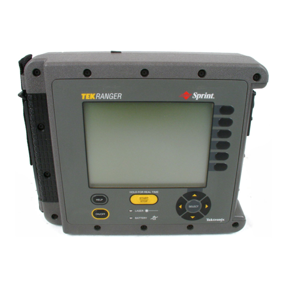
Operator Information This section summarizes TFS3031 connector, button, and softkey functions. A quick review of this section will familiarize you with the basic operation of the TFS3031, which may help when servicing the instrument. For complete operator information, refer to the TFS3031 TekRanger/TekRanger 2 User Manual. -
Page 29: Figure 1-1: Connector Adapter Installation
Operator Information Laser Output Port and Laser Output Port Connector Adapter The test fiber connects to the Laser Output port located on the side panel. Laser light is emitted into the test fiber from the Laser Output port. If both singlemode and multimode Laser Output ports are installed, the singlemode port is in top position and multimode port in bottom position. - Page 30 Operator Information CAUTION. Do not touch the exposed end of the Laser Output port with anything but the proper cleaning materials. See page NO TAG for cleaning instructions. To protect against damage, all ports should be capped with their dust caps when not in use.
-
Page 31: Updating The Instrument Software
Operator Information 4. Push the softkey again to confirm formatting. If you insert an unformatted disk while already in file storage, steps 2, 3, and 4 are displayed when you use the Save, Load, Copy, Delete, or Print file options that involve accessing the floppy disk (when toggling the softkey). -
Page 32: Buttons And Keys
Operator Information Buttons and Keys button and arrow keys: Move the cursors, manipulate the waveform, and edit events in the wave- form/table display. Select and change instrument setups. button powers the TFS3031 on and off. button provides on-screen descriptive information about the current instrument function or status. -
Page 33: Keyboard Definitions
Operator Information Keyboard Definitions The functions of the TFS3031’s front-panel controls can be duplicated using an optional keyboard connected to the keyboard connector (on upgraded instru- ments and instruments with serial numbers B030000 and above). The instrument accepts text entry from the keyboard whevever a character-selec- tion box is on the display (i.e., when entering fiber notes, a file name, or event notes). -
Page 34: Battery Recharging And Replacement
Battery Recharging and Replacement CAUTION. To prevent overheating, remove the TFS3031 from its carrying case during recharging. Do not open or mutilate the battery, nor expose it to fire or intense heat. It may explode. Avoid contact with electrolyte, which may damage eyes, skin, and clothing. -
Page 35: Power/Charger Adapter
The power/charger adapter may also be used to power the TFS3031 when the battery is discharged or removed. CAUTION. Using a power/charger adapter other than the one supplied by Tektronix may damage the TFS3031. Do not connect the power/charger adapter to the TFS3031 when the ambient temperature exceeds 40 C (104 F). -
Page 36: Nicad Battery Recharging Procedure
Battery Recharging and Replacement NiCad Battery Recharging Procedure To recharge the NiCad battery, plug the power/charger adapter into the port on the top of the TFS3031, and into an appropriate active power source (see Figure 1–2). The battery recharges as long as the power/charger adapter remains connected to the instrument and power source. -
Page 37: Tips For Maximizing Battery Life
Battery Recharging and Replacement LED glows a steady green when the power/charger adapter is connected and the battery has reached full charge. When the battery reaches full charge, the TFS3031 goes to trickle charge to maintain the full charge level. LED is off when the power/charger adapter disconnected (except for the flashing red condition). -
Page 38: Figure 1-3: Nicad Battery Removal
Battery Recharging and Replacement 2. Loosen the six screws that hold the battery compartment cover in place on the back of the instrument (see Figure 1–3). The screws are captive to prevent loss. 3. Disconnect the NiCad battery cable plug and lift the battery out of the case. The plug and connector snap together. - Page 39 Battery Recharging and Replacement 1–16 TFS3031 TekRanger/TekRanger 2 Service Manual...
-
Page 40: Specifications - Tekranger (Serial Nos. Below B052000)
Specifications – TekRanger (serial nos. below B052000) Standard 850 nm Multimode, Options 01 and 03 Table 1–4: Optical Signal Characteristics (850 nm Multimode, Options 01 and 03) µ 1–17 TFS3031 TekRanger/TekRanger 2 Service Manual... -
Page 41: Table 1-7: Single-Event Distance Measurement Repeatability
Specifications – TekRanger (serial nos. below B052000) Table 1–5: Vertical System Measurements (850 nm Multimode, Options 01 and 03) Table 1–6: Measurement Range (850 nm Multimode, Options 01 and 03) Table 1–7: Single-Event Distance Measurement Repeatability (850 nm Multimode, Options 01 and 03) 1–18 TFS3031 TekRanger/TekRanger 2 Service Manual... - Page 42 Specifications – TekRanger (serial nos. below B052000) Table 1–8: Vertical System Dynamic Range (850 nm Multimode, Options 01 and 03) µ Table 1–9: Horizontal System Dead Zone (850 nm Multimode, Options 01 and 03) µ 1–19 TFS3031 TekRanger/TekRanger 2 Service Manual...
- Page 43 Specifications – TekRanger (serial nos. below B052000) Table 1–10: Horizontal System Distance Span and Range (850 nm Multimode, Options 01 and 03) Table 1–11: System Measurement Accuracy (850 nm Multimode, Options 01 and 03) Table 1–12: Sample Density, Pulsewidth, and Range Combinations (850 nm Multimode, Options 01 and 03) Table 1–13: Bandwidth and Transient Characteristics (850 nm Multimode, Options 01 and 03) 1–20 TFS3031 TekRanger/TekRanger 2 Service Manual...
-
Page 44: Standard 1300 Nm Multimode, Option 03
Specifications – TekRanger (serial nos. below B052000) Standard 1300 nm Multimode, Option 03 Table 1–14: Optical Signal Characteristics (1300 nm Multimode, Option 03) µ 1–21 TFS3031 TekRanger/TekRanger 2 Service Manual... - Page 45 Specifications – TekRanger (serial nos. below B052000) 1–22 TFS3031 TekRanger/TekRanger 2 Service Manual...
- Page 46 Specifications – TekRanger (serial nos. below B052000) Table 1–15: Vertical System Dynamic Range (1300 nm Multimode, Option 03) µ Table 1–16: System Measurement Accuracy (1300 nm Multimode, Option 03) 1–23 TFS3031 TekRanger/TekRanger 2 Service Manual...
- Page 47 Specifications – TekRanger (serial nos. below B052000) Table 1–17: Horizontal System Dead Zone (1300 nm Multimode, Option 03) µ Table 1–18: Horizontal System Distance Span and Range (1300 nm Multimode, Option 03) 1–24 TFS3031 TekRanger/TekRanger 2 Service Manual...
- Page 48 Specifications – TekRanger (serial nos. below B052000) Table 1–19: Sample Density, Pulsewidth, and Range Combinations (1300 nm Multimode, Option 03) Table 1–20: Bandwidth and Transient Characteristics (1300 nm Multimode, Option 03) 1–25 TFS3031 TekRanger/TekRanger 2 Service Manual...
- Page 49 Specifications – TekRanger (serial nos. below B052000) Standard 1310 nm Singlemode, Options 04 and 06 Table 1–21: Optical Signal Characteristics (Standard 1310 nm Singlemode, Options 04 and 06) µ 1–26 TFS3031 TekRanger/TekRanger 2 Service Manual...
-
Page 50: Standard 1310 Nm Singlemode, Options 04 And 06
Specifications – TekRanger (serial nos. below B052000) Table 1–22: Vertical System Measurements (Standard 1310 nm Singlemode, Options 04 and 06) Table 1–23: Measurement Range (Standard 1310 nm Singlemode, Options 04 and 06) Table 1–24: Single-Event Distance Measurement Repeatability (Standard 1310 nm Singlemode, Options 04 and 06) 1–27 TFS3031 TekRanger/TekRanger 2 Service Manual... - Page 51 Specifications – TekRanger (serial nos. below B052000) Table 1–25: Vertical System Dynamic Range (Standard 1310 nm Singlemode, Options 04 and 06) 1–28 TFS3031 TekRanger/TekRanger 2 Service Manual...
- Page 52 Specifications – TekRanger (serial nos. below B052000) Table 1–26: Horizontal System Dead Zone (Standard 1310 nm Singlemode, Options 04 and 06) µ 1–29 TFS3031 TekRanger/TekRanger 2 Service Manual...
- Page 53 Specifications – TekRanger (serial nos. below B052000) Table 1–27: Horizontal System Distance Span and Range (Standard 1310 nm Singlemode, Options 04 and 06) 1–30 TFS3031 TekRanger/TekRanger 2 Service Manual...
- Page 54 Specifications – TekRanger (serial nos. below B052000) Table 1–28: Sample Density, Pulsewidth, and Range Combinations (Standard 1310 nm Singlemode, Options 04 and Table 1–29: Bandwidth and Transient Characteristics (Standard 1310 nm Singlemode, Options 04 and 06) 1–31 TFS3031 TekRanger/TekRanger 2 Service Manual...
- Page 55 Specifications – TekRanger (serial nos. below B052000) Standard 1550 nm Singlemode, Option 06 Table 1–30: Optical Signal Characteristics (Standard 1550 nm Singlemode, Option 06) µ 1–32 TFS3031 TekRanger/TekRanger 2 Service Manual...
-
Page 56: Standard 1550 Nm Singlemode, Option 06
Specifications – TekRanger (serial nos. below B052000) Table 1–31: Vertical System Measurements (Standard 1550 nm Singlemode, Option 06) Table 1–32: Measurement Range (Standard 1550 nm Singlemode, Option 06) Table 1–33: Single-Event Distance Measurement Repeatability (Standard 1550 nm Singlemode, Option 06) 1–33 TFS3031 TekRanger/TekRanger 2 Service Manual... - Page 57 Specifications – TekRanger (serial nos. below B052000) Table 1–34: Vertical System Dynamic Range (Standard 1550 nm Singlemode, Option 06) 1–34 TFS3031 TekRanger/TekRanger 2 Service Manual...
- Page 58 Specifications – TekRanger (serial nos. below B052000) Table 1–35: Horizontal System Dead Zone (Standard 1550 nm Singlemode, Option 06) µ 1–35 TFS3031 TekRanger/TekRanger 2 Service Manual...
- Page 59 Specifications – TekRanger (serial nos. below B052000) Table 1–36: Horizontal System Distance Span and Range (Standard 1550 nm Singlemode, Option 06) 1–36 TFS3031 TekRanger/TekRanger 2 Service Manual...
- Page 60 Specifications – TekRanger (serial nos. below B052000) Table 1–37: Sample Density, Pulsewidth, and Range Combinations (Standard 1550 nm Singlemode, Option 06) Table 1–38: Bandwidth and Transient Characteristics (Standard 1550 nm Singlemode, Option 06) 1–37 TFS3031 TekRanger/TekRanger 2 Service Manual...
- Page 61 Specifications – TekRanger (serial nos. below B052000) Extended Range 1310 nm Singlemode, Option 08 Table 1–39: Optical Signal Characteristics (Extended Range 1310 nm Singlemode, Option 08) µ 1–38 TFS3031 TekRanger/TekRanger 2 Service Manual...
-
Page 62: Extended Range 1310 Nm Singlemode, Option 08
Specifications – TekRanger (serial nos. below B052000) Table 1–40: Vertical System Measurements (Extended Range 1310 nm Singlemode, Option 08) Table 1–41: Measurement Range (Extended Range 1310 nm Singlemode, Option 08) Table 1–42: Single-Event Distance Measurement Repeatability (Extended Range 1310 nm Singlemode, Option 08) 1–39 TFS3031 TekRanger/TekRanger 2 Service Manual... - Page 63 Specifications – TekRanger (serial nos. below B052000) Table 1–43: Vertical System Dynamic Range (Extended Range 1310 nm Singlemode, Option 08) 1–40 TFS3031 TekRanger/TekRanger 2 Service Manual...
- Page 64 Specifications – TekRanger (serial nos. below B052000) Table 1–44: Horizontal System Dead Zone (Extended Range 1310 nm Singlemode, Option 08) µ 1–41 TFS3031 TekRanger/TekRanger 2 Service Manual...
- Page 65 Specifications – TekRanger (serial nos. below B052000) Table 1–45: Horizontal System Distance Span and Range (Extended Range 1310 nm Singlemode, Option 08) 1–42 TFS3031 TekRanger/TekRanger 2 Service Manual...
- Page 66 Specifications – TekRanger (serial nos. below B052000) Table 1–46: Sample Density, Pulsewidth, and Range Combinations (Extended Range 1310 nm Singlemode, Option 08) Table 1–47: Bandwidth and Transient Characteristics (Extended Range 1310 nm Singlemode, Option 08) 1–43 TFS3031 TekRanger/TekRanger 2 Service Manual...
- Page 67 Specifications – TekRanger (serial nos. below B052000) Extended Range 1550 nm Singlemode, Option 08 Table 1–48: Optical Signal Characteristics (Extended Range 1550 nm Singlemode, Option 08) µ 1–44 TFS3031 TekRanger/TekRanger 2 Service Manual...
-
Page 68: Extended Range 1550 Nm Singlemode, Option 08
Specifications – TekRanger (serial nos. below B052000) Table 1–49: Vertical System Measurements (Extended Range 1550 nm Singlemode, Option 08) Table 1–50: Measurement Range (Extended Range 1550 nm Singlemode, Option 08) Table 1–51: Single-Event Distance Measurement Repeatability (Extended Range 1550 nm Singlemode, Option 08) 1–45 TFS3031 TekRanger/TekRanger 2 Service Manual... - Page 69 Specifications – TekRanger (serial nos. below B052000) Table 1–52: Vertical System Dynamic Range (Extended Range 1550 nm Singlemode, Option 08) 1–46 TFS3031 TekRanger/TekRanger 2 Service Manual...
- Page 70 Specifications – TekRanger (serial nos. below B052000) Table 1–53: Horizontal System Dead Zone (Extended Range 1550 nm Singlemode, Option 08) µ 1–47 TFS3031 TekRanger/TekRanger 2 Service Manual...
- Page 71 Specifications – TekRanger (serial nos. below B052000) Table 1–54: Horizontal System Distance Span and Range (Extended Range 1550 nm Singlemode, Option 08) 1–48 TFS3031 TekRanger/TekRanger 2 Service Manual...
- Page 72 Specifications – TekRanger (serial nos. below B052000) Table 1–55: Sample Density, Pulsewidth, and Range Combinations (Extended Range 1550 nm Singlemode, Option 08) Table 1–56: Bandwidth and Transient Characteristics (Extended Range 1550 nm Singlemode, Option 08) 1–49 TFS3031 TekRanger/TekRanger 2 Service Manual...
- Page 73 Specifications – TekRanger (serial nos. below B052000) Extended Range 1550 nm Singlemode, Option 09 Table 1–57: Optical Signal Characteristics (Extended Range 1550 nm Singlemode, Option 09) µ 1–50 TFS3031 TekRanger/TekRanger 2 Service Manual...
-
Page 74: Extended Range 1550 Nm Singlemode, Option 09
Specifications – TekRanger (serial nos. below B052000) Table 1–58: Vertical System Measurements (Extended Range 1550 nm Singlemode, Option 09) Table 1–59: Measurement Range (Extended Range 1550 nm Singlemode, Option 09) Table 1–60: Single-Event Distance Measurement Repeatability (Extended Range 1550 nm Singlemode, Option 09) 1–51 TFS3031 TekRanger/TekRanger 2 Service Manual... - Page 75 Specifications – TekRanger (serial nos. below B052000) Table 1–61: Vertical System Dynamic Range (Extended Range 1550 nm Singlemode, Option 09) 1–52 TFS3031 TekRanger/TekRanger 2 Service Manual...
- Page 76 Specifications – TekRanger (serial nos. below B052000) Table 1–62: Horizontal System Dead Zone (Extended Range 1550 nm Singlemode, Option 09) µ 1–53 TFS3031 TekRanger/TekRanger 2 Service Manual...
- Page 77 Specifications – TekRanger (serial nos. below B052000) Table 1–63: Horizontal System Distance Span and Range (Extended Range 1550 nm Singlemode, Option 09) 1–54 TFS3031 TekRanger/TekRanger 2 Service Manual...
- Page 78 Specifications – TekRanger (serial nos. below B052000) Table 1–64: Sample Density, Pulsewidth, and Range Combinations (Extended Range 1550 nm Singlemode, Option 09) Table 1–65: Bandwidth and Transient Characteristics (Extended Range 1550 nm Singlemode, Option 09) 1–55 TFS3031 TekRanger/TekRanger 2 Service Manual...
-
Page 79: Power
Specifications – TekRanger (serial nos. below B052000) Power Display Size and Weight 1–56 TFS3031 TekRanger/TekRanger 2 Service Manual... -
Page 80: Rs232C Serial Port
Specifications – TekRanger (serial nos. below B052000) RS232C Serial Port Parallel Port Keyboard Port 1–57 TFS3031 TekRanger/TekRanger 2 Service Manual... -
Page 81: Environmental
Specifications – TekRanger (serial nos. below B052000) Environmental 1–58 TFS3031 TekRanger/TekRanger 2 Service Manual... - Page 82 Specifications – TekRanger (serial nos. below B052000) 1–59 TFS3031 TekRanger/TekRanger 2 Service Manual...
- Page 83 Specifications – TekRanger (serial nos. below B052000) 1–60 TFS3031 TekRanger/TekRanger 2 Service Manual...
-
Page 84: Specifications - Tekranger 2 (Serial Nos. B052000 And Above)
Specifications – TekRanger 2 (serial nos. B052000 and above) Standard 850 nm Multimode, Options 01 and 03 Table 1–66: Optical Signal Characteristics (850 nm Multimode, Options 01 and 03) µ 1–61 TFS3031 TekRanger/TekRanger 2 Service Manual... - Page 85 Specifications – TekRanger 2 (serial nos. B052000 and above) Table 1–67: Vertical System Measurements (850 nm Multimode, Options 01 and 03) Table 1–68: Single-Event Distance Measurement Repeatability (850 nm Multimode, Options 01 and 03) 1–62 TFS3031 TekRanger/TekRanger 2 Service Manual...
- Page 86 Specifications – TekRanger 2 (serial nos. B052000 and above) Table 1–69: Vertical System Dynamic Range (850 nm Multimode, Options 01 and 03) µ Table 1–70: System Measurement Accuracy (850 nm Multimode, Options 01 and 03) 1–63 TFS3031 TekRanger/TekRanger 2 Service Manual...
- Page 87 Specifications – TekRanger 2 (serial nos. B052000 and above) Table 1–71: Horizontal System Dead Zone (850 nm Multimode, Options 01 and 03) µ Table 1–72: Horizontal System Distance Span and Range (850 nm Multimode, Options 01 and 03) 1–64 TFS3031 TekRanger/TekRanger 2 Service Manual...
- Page 88 Specifications – TekRanger 2 (serial nos. B052000 and above) Table 1–73: Sample Density, Pulsewidth, and Range Combinations (850 nm Multimode, Options 01 and 03) Table 1–74: Bandwidth and Transient Characteristics (850 nm Multimode, Options 01 and 03) 1–65 TFS3031 TekRanger/TekRanger 2 Service Manual...
-
Page 89: Standard 1300 Nm Multimode, Option 03
Specifications – TekRanger 2 (serial nos. B052000 and above) Standard 1300 nm Multimode, Option 03 Table 1–75: Optical Signal Characteristics (1300 nm Multimode, Option 03) µ 1–66 TFS3031 TekRanger/TekRanger 2 Service Manual... - Page 90 Specifications – TekRanger 2 (serial nos. B052000 and above) Table 1–76: Vertical System Measurements (1300 nm Multimode, Option 03) Table 1–77: Measurement Range (1300 nm Multimode, Option 03) Table 1–78: Single-Event Distance Measurement Repeatability (1300 nm Multimode, Option 03) 1–67 TFS3031 TekRanger/TekRanger 2 Service Manual...
- Page 91 Specifications – TekRanger 2 (serial nos. B052000 and above) Table 1–79: Vertical System Dynamic Range (1300 nm Multimode, Option 03) µ 1–68 TFS3031 TekRanger/TekRanger 2 Service Manual...
- Page 92 Specifications – TekRanger 2 (serial nos. B052000 and above) Table 1–80: Horizontal System Dead Zone (1300 nm Multimode, Option 03) µ Table 1–81: Horizontal System Distance Span and Range (1300 nm Multimode, Option 03) 1–69 TFS3031 TekRanger/TekRanger 2 Service Manual...
- Page 93 Specifications – TekRanger 2 (serial nos. B052000 and above) Table 1–82: System Measurement Accuracy (1300 nm Multimode, Options 03) Table 1–83: Sample Density, Pulsewidth, and Range Combinations (1300 nm Multimode, Option 03) Table 1–84: Bandwidth and Transient Characteristics (1300 nm Multimode, Option 03) 1–70 TFS3031 TekRanger/TekRanger 2 Service Manual...
- Page 94 Specifications – TekRanger 2 (serial nos. B052000 and above) Standard 1310 nm Singlemode, Options 04 and 06 Table 1–85: Optical Signal Characteristics (Standard 1310 nm Singlemode, Options 04 and 06) µ 1–71 TFS3031 TekRanger/TekRanger 2 Service Manual...
-
Page 95: Standard 1310 Nm Singlemode, Options 04 And 06
Specifications – TekRanger 2 (serial nos. B052000 and above) Table 1–86: Vertical System Measurements (Standard 1310 nm Singlemode, Options 04 and 06) Table 1–87: Single-Event Distance Measurement Repeatability (Standard 1310 nm Singlemode, Options 04 and 06) Table 1–88: System Measurement Accuracy (Standard 1310 nm Singlemode, Options 04 and 06) 1–72 TFS3031 TekRanger/TekRanger 2 Service Manual... - Page 96 Specifications – TekRanger 2 (serial nos. B052000 and above) Table 1–89: Vertical System Dynamic Range (Standard 1310 nm Singlemode, Options 04 and 06) 1–73 TFS3031 TekRanger/TekRanger 2 Service Manual...
- Page 97 Specifications – TekRanger 2 (serial nos. B052000 and above) Table 1–90: Horizontal System Dead Zone (Standard 1310 nm Singlemode, Options 04 and 06) µ 1–74 TFS3031 TekRanger/TekRanger 2 Service Manual...
- Page 98 Specifications – TekRanger 2 (serial nos. B052000 and above) Table 1–91: Horizontal System Distance Span and Range (Standard 1310 nm Singlemode, Options 04 and 06) 1–75 TFS3031 TekRanger/TekRanger 2 Service Manual...
- Page 99 Specifications – TekRanger 2 (serial nos. B052000 and above) Table 1–92: Sample Density, Pulsewidth, and Range Combinations (Standard 1310 nm Singlemode, Options 04 and Table 1–93: Bandwidth and Transient Characteristics (Standard 1310 nm Singlemode, Options 04 and 06) 1–76 TFS3031 TekRanger/TekRanger 2 Service Manual...
- Page 100 Specifications – TekRanger 2 (serial nos. B052000 and above) Standard 1550 nm Singlemode, Option 06 Table 1–94: Optical Signal Characteristics (Standard 1550 nm Singlemode, Option 06) µ 1–77 TFS3031 TekRanger/TekRanger 2 Service Manual...
-
Page 101: Standard 1550 Nm Singlemode, Option 06
Specifications – TekRanger 2 (serial nos. B052000 and above) Table 1–95: Vertical System Measurements (Standard 1550 nm Singlemode, Option 06) Table 1–96: Single-Event Distance Measurement Repeatability (Standard 1550 nm Singlemode, Option 06) Table 1–97: System Measurement Accuracy (Standard 1550 nm Singlemode, Option 06) 1–78 TFS3031 TekRanger/TekRanger 2 Service Manual... - Page 102 Specifications – TekRanger 2 (serial nos. B052000 and above) Table 1–98: Vertical System Dynamic Range (Standard 1550 nm Singlemode, Option 06) 1–79 TFS3031 TekRanger/TekRanger 2 Service Manual...
- Page 103 Specifications – TekRanger 2 (serial nos. B052000 and above) Table 1–99: Horizontal System Dead Zone (Standard 1550 nm Singlemode, Option 06) µ 1–80 TFS3031 TekRanger/TekRanger 2 Service Manual...
- Page 104 Specifications – TekRanger 2 (serial nos. B052000 and above) Table 1–100: Horizontal System Distance Span and Range (Standard 1550 nm Singlemode, Option 06) 1–81 TFS3031 TekRanger/TekRanger 2 Service Manual...
- Page 105 Specifications – TekRanger 2 (serial nos. B052000 and above) Table 1–101: Sample Density, Pulsewidth, and Range Combinations (Standard 1550 nm Singlemode, Option 06) Table 1–102: Bandwidth and Transient Characteristics (Standard 1550 nm Singlemode, Option 06) 1–82 TFS3031 TekRanger/TekRanger 2 Service Manual...
-
Page 106: Extended Range 1310/1550 Nm Singlemode, Option 10
Specifications – TekRanger 2 (serial nos. B052000 and above) Extended Range 1310/1550 nm Singlemode, Option 10 Table 1–103: Optical Signal Characteristics (Extended Range 1310/1550 nm Singlemode, Option 10) µ 1–83 TFS3031 TekRanger/TekRanger 2 Service Manual... - Page 107 Specifications – TekRanger 2 (serial nos. B052000 and above) Table 1–104: Vertical System Measurements (Extended Range 1310/1550 nm Singlemode, Option 10) Table 1–105: Single-Event Distance Measurement Repeatability (Extended Range 1310/1550 nm Singlemode, Option 10) Table 1–106: System Measurement Accuracy (Extended Range 1310/1550 nm Singlemode, Option 10) 1–84 TFS3031 TekRanger/TekRanger 2 Service Manual...
- Page 108 Specifications – TekRanger 2 (serial nos. B052000 and above) Table 1–107: Vertical System Dynamic Range (Extended Range 1310/1550 nm Singlemode, Option 10) 1–85 TFS3031 TekRanger/TekRanger 2 Service Manual...
- Page 109 Specifications – TekRanger 2 (serial nos. B052000 and above) Table 1–108: Horizontal System Dead Zone (Extended Range 1550 nm Singlemode, Option 08) µ 1–86 TFS3031 TekRanger/TekRanger 2 Service Manual...
- Page 110 Specifications – TekRanger 2 (serial nos. B052000 and above) Table 1–109: Horizontal System Distance Span and Range (Extended Range 1550 nm Singlemode, Option 08) 1–87 TFS3031 TekRanger/TekRanger 2 Service Manual...
- Page 111 Specifications – TekRanger 2 (serial nos. B052000 and above) Table 1–110: Sample Density, Pulsewidth, and Range Combinations (Extended Range 1550 nm Singlemode, Option 08) Table 1–111: Bandwidth and Transient Characteristics (Extended Range 1550 nm Singlemode, Option 08) 1–88 TFS3031 TekRanger/TekRanger 2 Service Manual...
- Page 112 Specifications – TekRanger 2 (serial nos. B052000 and above) 1625 nm Singlemode, Option 12 Table 1–112: Optical Signal Characteristics (1625 nm Singlemode, Option 12) µ 1–89 TFS3031 TekRanger/TekRanger 2 Service Manual...
-
Page 113: 1625 Nm Singlemode, Option 12
Specifications – TekRanger 2 (serial nos. B052000 and above) Table 1–113: Vertical System Measurements (1625 nm Singlemode, Option 12) Table 1–114: Single-Event Distance Measurement Repeatability (1625 nm Singlemode, Option 12) 1–90 TFS3031 TekRanger/TekRanger 2 Service Manual... - Page 114 Specifications – TekRanger 2 (serial nos. B052000 and above) Table 1–115: Vertical System Dynamic Range (1625 nm Singlemode, Option 12) 1–91 TFS3031 TekRanger/TekRanger 2 Service Manual...
- Page 115 Specifications – TekRanger 2 (serial nos. B052000 and above) Table 1–116: Horizontal System Dead Zone (1625 nm Singlemode, Option 12) µ 1–92 TFS3031 TekRanger/TekRanger 2 Service Manual...
- Page 116 Specifications – TekRanger 2 (serial nos. B052000 and above) Table 1–117: Horizontal System Distance Span and Range (1625 nm Singlemode, Option 12) 1–93 TFS3031 TekRanger/TekRanger 2 Service Manual...
- Page 117 Specifications – TekRanger 2 (serial nos. B052000 and above) Table 1–118: Sample Density, Pulsewidth, and Range Combinations (1625 nm Singlemode, Option 12) Table 1–119: Bandwidth and Transient Characteristics (1625 nm Singlemode, Option 12) 1–94 TFS3031 TekRanger/TekRanger 2 Service Manual...
-
Page 118: Power
Specifications – TekRanger 2 (serial nos. B052000 and above) Power Display Size and Weight 1–95 TFS3031 TekRanger/TekRanger 2 Service Manual... -
Page 119: Rs232C Serial Port
Specifications – TekRanger 2 (serial nos. B052000 and above) RS232C Serial Port Parallel Port Keyboard Port 1–96 TFS3031 TekRanger/TekRanger 2 Service Manual... -
Page 120: Environmental
Specifications – TekRanger 2 (serial nos. B052000 and above) Environmental 1–97 TFS3031 TekRanger/TekRanger 2 Service Manual... - Page 121 Specifications – TekRanger 2 (serial nos. B052000 and above) 1–98 TFS3031 TekRanger/TekRanger 2 Service Manual...
- Page 122 Specifications – TekRanger 2 (serial nos. B052000 and above) Table 1–120: Certifications and compliances Category Standards or description EC Declaration of Conformity – Meets intent of Directive 89/336/EEC for Electromagnetic Compatibility. Compliance was demonstrated to the following specifications as listed in the Official Journal of the European Union: EN 50081-1 Emissions: EN 55022 Class B Radiated and Conducted Emissions...
- Page 123 Specifications – TekRanger 2 (serial nos. B052000 and above) Table 1–120: Certifications and compliances (cont.) Category Standards or description Installation (Overvoltage) CAT I Secondary (signal level) or battery operated circuits of electronic equipment. Category CAT II Local-level mains (wall sockets). Equipment at this level includes appliances, portable tools, and similar products.
-
Page 124: Accessories And Options
Accessories and Options Table 1–121: Standard Accessories 1–101 TFS3031 TekRanger/TekRanger 2 Service Manual... - Page 125 Accessories and Options Table 1–122: Optional Accessories 1–102 TFS3031 TekRanger/TekRanger 2 Service Manual...
- Page 126 Accessories and Options Table 1–123: Configuration Options 1–103 TFS3031 TekRanger/TekRanger 2 Service Manual...
- Page 127 Accessories and Options Table 1–124: Power/Charger Adapter Cord Options Table 1–125: Laser Output Port Options 1–104 TFS3031 TekRanger/TekRanger 2 Service Manual...
- Page 128 Accessories and Options Table 1–126: Connector Adapter Options Table 1–127: Performance Check Software Table 1–128: Operating System Software 1–105 TFS3031 TekRanger/TekRanger 2 Service Manual...
- Page 129 Accessories and Options 1–106 TFS3031 TekRanger/TekRanger 2 Service Manual...
-
Page 130: Theory Of Operation
Theory of Operation Power–Supply Board External Power Analog Digital Software: Keypad Battery * Power Management * Keypad Speaker Singlemode and Multimode Optical Module Assemblies Laser Output Optical MAIN31 Board User Interfaces Port Keyboard Analog Digital Subsystem Digital RS232C (Print, PC) Parallel (Print) Control Logic Floppy–Disk Drive... -
Page 131: Theory Of Operation
Theory of Operation Theory of Operation The TFS3031 consists of the following major components: User interface Keypad Liquid-crystal display (LCD) Floppy-disk drive Serial port Parallel port Singlemode optical port (optional) Multimode optical port (optional) Keyboard Battery External power port Internal printed circuit boards Singlemode data-acquisition system (SMDAS) board (optional) Multimode data-acquisition system (MMDAS) board (optional) Power-supply board... - Page 132 Theory of Operation The microprocessor on the power-supply board decodes key presses on the keypad and sends the key-press information to the main board. The power-supply board receives commands from the main board and power switch to enable or disable power to the SMDAS board, MMDAS board, main board, and LCD backlight.
- Page 133 Theory of Operation 2–4 TFS3031 TekRanger/TekRanger 2 Service Manual...
-
Page 134: Performance Check - Tekranger
Performance Check – TekRanger Introduction These performance checks ensure that the TFS3031 TekRanger is operating properly and conforms to instrument specifications as listed under Specifications – TekRanger (serial nos. below B052000) in Section 1. This perrformance check procedure applies to TekRanger instruments with serial numbers below B052000. -
Page 135: Adjustments
Performance Check – TekRanger (serial nos. below B052000) Tektronix performance check software The fiber test fixtures are not supplied by Tektronix. See instructions starting on page 3–6 for information about how to build your own fixtures. A characterization and tolerance data sheet for all events on the event-detection test fixtures is required prior to use. - Page 136 Performance Check – TekRanger (serial nos. below B052000) Dynamic range (dB) ~1.5 dB SNR = 1 (1 ) Each of these definitions for noise floor have good points and bad points. The definition for noise floor for the TFS3031 is the 1-sigma level. The 1-sigma level is the level where the signal from the backscatter is equal to the standard deviation of the noise.
- Page 137 Performance Check – TekRanger (serial nos. below B052000) Some of the characteristics of event detection depend on signal level and noise level, which can degrade as lasers age and as the front-panel optical connector becomes worn or damaged. This second group of characteristics will degrade both dynamic-range tests and event-detection tests.
- Page 138 Performance Check – TekRanger (serial nos. below B052000) when the waveform finally recovers to within 0.5 dB of backscatter following the event. Dead Zone (refl) 0.5 dB 0.5 dB Attenuation dead zone should measure the recovery time of the OTDR due to the reflective event, and ignore noise unrelated to the event.
-
Page 139: Singlemode Event-Detection Test Fixture Build Description
Performance Check – TekRanger (serial nos. below B052000) Singlemode Event-Detection Test Fixture Build Description Overview 10 km 25 km 10 km 1 km 0.15 dB 0.15 dB 0.50 dB 7 km 1 km 0.5 dB 0.50 dB Connector 2 km 0.15 dB Connector TFS3031... - Page 140 Performance Check – TekRanger (serial nos. below B052000) The fixture consists of two connector pigtails (FCPC), two 0.5 dB fusion splices, three 0.15 dB fusion splices, one Norland UV-cured mechanical splice, and several construction splices that are 0.1 dB or less. The fixture waveform consists of a series of reflective and nonreflective events.
-
Page 141: Figure 3-2: Scatter Plot For 50 M Event
Performance Check – TekRanger (serial nos. below B052000) Scatter plots are constructed showing loss vs. distance data points for each event. If 40 instruments are used, and each instrument is allowed to scan the fiber five times, the total number of data points is 200. Figure 4–8 is an example scatter plot for a 50 m event. -
Page 142: Singlemode Dynamic-Range Test Fixture Build Description
Tools and equipment required: Optical fiber stripper for removing fiber buffer Optical fiber cleaver Optical fiber fusion splicer Optical time-domain reflectometer, Tektronix TFP2A with FS1315 singlemode optical module Hand tools as required to assemble cabinet 3–9 TFS3031 TekRanger/TekRanger 2 Service Manual... -
Page 143: Figure 3-3: Singlemode Dead-Zone Test Fixture
Performance Check – TekRanger (serial nos. below B052000) All fiber is Corning SMF-28 1310/1550 multiplexer (2 each) 1310 nm 6” 10” 10” Fusion splices 1550 nm 6” 10” 10” 3.9 km FCPC 4.4 km connector 90 degree cleave 5/95% splitter Protective sheath over cleaved end Figure 3–3: Singlemode Dead-Zone Test Fixture... -
Page 144: Figure 3-4: Desired Otdr Signature
Performance Check – TekRanger (serial nos. below B052000) 7. Connect the FCPC connector to the OTDR. Do not use an interface or jumper cable. Measure the 1310-nm reflectance (return loss) at the event located at 3.9 km. (See figure 3–4.) Return loss: 40 dB dB) at 1310 and 1550 nm. -
Page 145: Multimode Dynamic-Range Test Fixture
Performance Check – TekRanger (serial nos. below B052000) Periodic Maintenance At six-month intervals, measure the reflectance at each wavelength to confirm the reflectance is 40 dB ( 1 dB). Multimode Dynamic-Range Test Fixture The multimode dynamic-range test fixture consists of 4.4 to 8.8 kilometers of 62.5/125 µm fiber, with connectors and fusion splices as shown below. -
Page 146: Multimode Event-Detection And Dead-Zone Test Fixture
Performance Check – TekRanger (serial nos. below B052000) Multimode Event-Detection and Dead-Zone Test Fixture Construct the multimode event-detection and dead-zone test fixture as shown in figure 3–6. Denotes cleaved end Denotes splice 1 X 2 multimode 62.5/125 µm 7/93% multimode splitter FC connector Secondary output... -
Page 147: Figure 3-7: Multimode Event-Detection And Dead-Zone Test Fixture: Otdr Trace
Performance Check – TekRanger (serial nos. below B052000) 0.000 1.000 2.000 3.000 Figure 3–7: Multimode Event-Detection and Dead-Zone Test Fixture: OTDR Trace 3–14 TFS3031 TekRanger/TekRanger 2 Service Manual... -
Page 148: Setup
Performance Check – TekRanger (serial nos. below B052000) Setup CAUTION. Do not fire the laser (push the button) unless a fiber is connected to the Laser Output port. Damage to internal electronics can result. 1. Connect the power/charger adapter to the TFS3031 and a suitable AC power source. -
Page 149: Power-On Initialization Check
Performance Check – TekRanger (serial nos. below B052000) Power-On Initialization Check Push the button to power on the TFS3031. This power-on screen indicates successful initialization, and shows that all subsystems are operating properly. 3–16 TFS3031 TekRanger/TekRanger 2 Service Manual... -
Page 150: Power/Charger Adapter Check
Performance Check – TekRanger (serial nos. below B052000) Power/Charger Adapter Check When the power/charger adapter is disconnected, and the TFS3031 has less than 10 minutes of operating time left on the battery, the BATTERY LED on the front panel should flash red. When the power/charger adapter is connected and charging the battery, the BATTERY LED on the front panel should flash green, and a ‘‘power plug’’... -
Page 151: Floppy Disk Drive Check
Performance Check – TekRanger (serial nos. below B052000) Floppy Disk Drive Check This check is to be performed only on instruments that have the optional floppy disk drive. 1. Make sure that the waveform is displayed from the previous optical check (push the softkey to display the waveform). -
Page 152: Keyboard Check (Option 19)
Performance Check – TekRanger (serial nos. below B052000) Keyboard Check (option 19) 1. Connect external keyboard to the TFS3031 (upgraded instruments and instruments with serial numbers B030000 and above). 2. Three LEDs on the keyboard light up for about two seconds, then turn off. This indicates that keyboard power is available. -
Page 153: Singlemode Dynamic Range Check
The singlemode dynamic range check is an automated test using an IBM-com- patible personal computer (386 or better) with a serial port, and the Tektronix performance test software package (part number 119–5130–xx). To use the performance test software, see the instructions contained in the readme file that comes with the software package. -
Page 154: Singlemode Event-Detection Check
Performance Check – TekRanger (serial nos. below B052000) Singlemode Event-Detection Check NOTE. If the instrument has two Laser Output ports, this check must be done on both ports. If the instrument has two wavelengths, this check must be done on both wavelengths. -
Page 155: Singlemode Dead-Zone Check
Performance Check – TekRanger (serial nos. below B052000) Singlemode Dead-Zone Check NOTE. If the instrument has two laser output ports, this check must be done on both ports. If the instrument has two wavelengths, this check must be done on both wavelengths. - Page 156 Performance Check – TekRanger (serial nos. below B052000) 11. Push the softkey to again select the first cursor as the active cursor. 12. Position the active cursor on the steepest part of the rising edge of the pulse of the event in question. 13.
-
Page 157: Multimode Dynamic Range Check
The multimode dynamic range check is an automated test using an IBM-compat- ible personal computer (386 or better) with a serial port, and the Tektronix performance test software package (part number 119–5130–xx). To use the performance test software, see the instructions contained in the readme file that comes with the software package. -
Page 158: Multimode Event-Detection Check
Performance Check – TekRanger (serial nos. below B052000) Multimode Event-Detection Check NOTE. If the instrument has two Laser Output ports, this check must be done on both ports. If the instrument has two wavelengths, this check must be done on both wavelengths. -
Page 159: Multimode Dead-Zone Check
Performance Check – TekRanger (serial nos. below B052000) Multimode Dead-Zone Check NOTE. If the instrument has two laser output ports, this check must be done on both ports. If the instrument has two wavelengths, this check must be done on both wavelengths. - Page 160 Performance Check – TekRanger (serial nos. below B052000) 11. Push the softkey to again select the first cursor as the active cursor. 12. Position the active cursor on the steepest part of the rising edge of the pulse of the event in question. 13.
-
Page 161: Multimode Distance Accuracy Check
Performance Check – TekRanger (serial nos. below B052000) Multimode Distance Accuracy Check The multimode distance accuracy check is a test using a test fixture made up of a 2.2 km length of multimode fiber with known length (time of flight). 1. -
Page 162: Performance Check - Tekranger 2
Performance Check – TekRanger 2 Introduction These performance checks ensure that the TFS3031 TekRanger 2 is operating properly and conforms to instrument specifications as listed under Specifications – TekRanger 2 (serial nos. B052000 and above) in Section 1. This performance check procedure applies to TekRanger 2 instruments, with serial numbers B052000 and above. -
Page 163: Adjustments
Performance Check – TekRanger 2 (serial nos. B052000 and above) ST/PC to ST/PC multimode jumper cable, 1-meter length The fiber test fixtures are not supplied by Tektronix. See instructions starting on page 4–6 for information about how to build your own fixtures. A characterization and tolerance data sheet for all events on the event-detection test fixtures is required prior to use. - Page 164 Performance Check – TekRanger 2 (serial nos. B052000 and above) Dynamic range (dB) ~1.5 dB SNR = 1 (1 ) Event Detection Noise is always present on the measured waveform. This noise causes location and loss measurements to vary slightly from one measurement to the next. The event-detection test measures the repeatability of measuring a series of events on a special test fiber.
- Page 165 Performance Check – TekRanger 2 (serial nos. B052000 and above) 1.5 dB Event dead zone Although it would be nice to verify the event-detection specification by physically moving two reflective events closer together until there is only a 1.5-dB dip between events, this is difficult to do. An alternate method is to measure the displayed pulse width from a reflection, 1.5 dB below the peak.
- Page 166 TFS3031 measures the reflection. The measurement must be within 4 dB of the actual value. Event Loss and Distance Tektronix has developed a unique process to allow the event loss and distance Accuracy accuracy of the TFS3031 singlemode options to be traceable to NIST (National Institute of Standards and Technology).
-
Page 167: Singlemode Range Test Fixture
Performance Check – TekRanger 2 (serial nos. B052000 and above) Singlemode Range Test Fixture This test fixture is used to verify measurement range and dynamic range. Overall, it consists of six 25-km segments of Corning SMF28 fiber intercon- nected with 1-m jumpers. The fixture is to have no more than 48 dB end-to-end loss at 1550 nm. -
Page 168: Singlemode Dead-Zone Test Fixture
Performance Check – TekRanger 2 (serial nos. B052000 and above) Singlemode Dead-Zone Test Fixture The dead-zone test fixture is used to verify event and attenuation dead zone. It consists of two 1.1-km ( 100 m) spools of Corning SMF28 singlemode fiber including: 95/5 singlemode coupler 1310nm/1550 nm WDM... - Page 169 8. Permanently protect cleaves from contamination. 9. Connect a Tektronix TFP2A with an FS1315 module to the FC/PC connector. (The TFP2A must have firmware version 1.03M or higher.) 10. Turn on power to the TFP2A.
-
Page 170: Singlemode Reflectance Test Fixture
Performance Check – TekRanger 2 (serial nos. B052000 and above) Singlemode Reflectance Test Fixture The reflectance test fixture is used to verify the reflectance accuracy of the TFS3031. It consists of one 2.2-km ( 250 m) spool of Corning SMF28 singlemode fiber, including: JDS Fitel BR1 variable backreflector with FC/APC connector FC/PC connector... -
Page 171: Singlemode Loss And Distance Accuracy Test Fixture
Performance Check – TekRanger 2 (serial nos. B052000 and above) Singlemode Loss and Distance Accuracy Test Fixture This test fixture is used to verify the loss and distance accuracy of the TFS3031. It consists of two 4.4-km spools and one 8.8-km spool of Corning SMF28 singlemode fiber. -
Page 172: Multimode Dynamic-Range Test Fixture
Performance Check – TekRanger 2 (serial nos. B052000 and above) Multimode Dynamic-Range Test Fixture The multimode dynamic-range test fixture consists of 8.8 kilometers of 62.5/125 µm fiber, with connectors and fusion splices as shown below. 8.8 km spool of 62.5/125 µm Denotes splice multimode fiber 62.5/125 µm multimode... -
Page 173: Multimode Event-Detection And Dead-Zone Test Fixture
Performance Check – TekRanger 2 (serial nos. B052000 and above) Multimode Event-Detection and Dead-Zone Test Fixture Construct the multimode event-detection and dead-zone test fixture as shown in figure 4–6. Denotes cleaved end Denotes splice 1 X 2 multimode 62.5/125 µm 7/93% multimode splitter... -
Page 174: Figure 4-7: Multimode Event-Detection And Dead-Zone Test Fixture: Otdr Trace
Performance Check – TekRanger 2 (serial nos. B052000 and above) 0.000 1.000 2.000 3.000 Figure 4–7: Multimode Event-Detection and Dead-Zone Test Fixture: OTDR Trace Statistical To characterize test fixture distances and losses, test the fixture using a large Characterization of number (approximately 40 units) of identically configured TFS3031 instruments. -
Page 175: Figure 4-8: Scatter Plot For 50 M Event
Performance Check – TekRanger 2 (serial nos. B052000 and above) Loss (dB) Distance (m) Figure 4–8: Scatter Plot for 50 m Event Once the data points are gathered, a confidence area can be drawn so that 95 percent of all subsequent data will fall within the area. The suggested area corresponds to the 1.96-σ... - Page 176 Performance Check – TekRanger 2 (serial nos. B052000 and above) The location confidence range calculated by the above formula is the range on either side of a sample mean where 95 percent of the measurements of a properly functioning unit are located. 4–15 TFS3031 TekRanger/TekRanger 2 Service Manual...
-
Page 177: Setup
Performance Check – TekRanger 2 (serial nos. B052000 and above) Setup CAUTION. Do not fire the laser (push the button) unless a fiber is connected to the Laser Output port. Damage to internal electronics can result. 1. Connect the power/charger adapter to the TFS3031 and a suitable AC power source. - Page 178 Performance Check – TekRanger 2 (serial nos. B052000 and above) Fiber test fixture Power/charger adapter 4. Check that loss at the front-panel connection is minimized (0.75 dB or less). a. Press the Setup softkey to display the Test Setup menu, and set the range to 1 km and the pulse width to 5 m.
-
Page 179: Power-On Initialization Check
Performance Check – TekRanger 2 (serial nos. B052000 and above) Power-On Initialization Check Push the button to power on the TFS3031. This power-on screen ON/OFF indicates successful initialization, and shows that all subsystems are operating properly. NOTE. Software versions may be different from the version shown in the illustration above. -
Page 180: Power/Charger Adapter Check
Performance Check – TekRanger 2 (serial nos. B052000 and above) Power/Charger Adapter Check The charge level of the battery is always displayed in the upper right screen. When the power/charger adapter is connected and charging the battery, the BATTERY LED on the front panel flashes green, and a “power plug” indicator is displayed below the battery indicator. - Page 181 Performance Check – TekRanger 2 (serial nos. B052000 and above) Power plug indicator Battery LED 4–20 TFS3031 TekRanger/TekRanger 2 Service Manual...
-
Page 182: Floppy Disk Drive Check (Option 11)
Performance Check – TekRanger 2 (serial nos. B052000 and above) Floppy Disk Drive Check (Option 11) This check is to be performed only on instruments that have the optional floppy disk drive. 1. Make sure that the waveform is displayed from the previous optical check (push the softkey to display the waveform). -
Page 183: Keyboard Check (Option 19)
Performance Check – TekRanger 2 (serial nos. B052000 and above) Keyboard Check (Option 19) 1. Connect external keyboard to the TFS3031 (upgraded instruments and instruments with serial numbers B030000 and above). 2. Three LEDs on the keyboard light up for about two seconds, then turn off. This indicates that keyboard power is available. -
Page 184: Singlemode Dynamic Range Check
Performance Check – TekRanger 2 (serial nos. B052000 and above) Singlemode Dynamic Range Check NOTE. If the instrument has two wavelengths, this check must be done on both wavelengths. Longest Pulse Width The longest pulse width is 2000 m for options 04 and 06, and 3200 m for option 10 and Option 12. -
Page 185: Figure 4-9: Singlemode Dynamic-Range Test Waveform, Longest Pulse Width
Performance Check – TekRanger 2 (serial nos. B052000 and above) Figure 4–9: Singlemode Dynamic-Range Test Waveform, Longest Pulse Width 10. Press the Zoom On softkey to zoom into the front section of the pulse. 4–24 TFS3031 TekRanger/TekRanger 2 Service Manual... -
Page 186: Figure 4-10: Singlemode Dynamic-Range Check, Longest Pulse Width, Zero Intercept
Performance Check – TekRanger 2 (serial nos. B052000 and above) 11. Extrapolate the zero-meter backscatter intercept by drawing a straight line on the backscatter across the incident pulse to the zero-meter point. See figure 4–10. Note where this line intersects the loss axis, about 29.75 dB in the example shown below. -
Page 187: Figure 4-11: Singlemode Dynamic-Range Check, Longest Pulse Width, 98% Noise Level
Performance Check – TekRanger 2 (serial nos. B052000 and above) 16. Identify the ten highest points and draw a line parallel with the distance axis so the ten highest points fall above the line. See figure 4–11. Ten noise spikes fall above this line, 0dB in this case Figure 4–11: Singlemode Dynamic-Range Check, Longest Pulse Width, 98% Noise Level 17. - Page 188 Performance Check – TekRanger 2 (serial nos. B052000 and above) 500-Meter Pulse Width 1. Clean the connector on the TFS3031 and the TFS3031 singlemode dynamic- range test fixture. 2. Connect the TFS3031 to the dynamic-range test fixture and turn on power to the instrument.
-
Page 189: Figure 4-12: Singlemode Dynamic-Range Test Waveform, 500-M Pulse Width
Performance Check – TekRanger 2 (serial nos. B052000 and above) 9. When the waveform acquisition is complete, you should see a waveform similar to the one in figure 4–12. Figure 4–12: Singlemode Dynamic-Range Test Waveform, 500-m Pulse Width 10. Press the Zoom On softkey to zoom into the front section of the pulse. 4–28 TFS3031 TekRanger/TekRanger 2 Service Manual... -
Page 190: Figure 4-13: Singlemode Dynamic-Range Check, 500-M Pulse Width, Zero Intercept
Performance Check – TekRanger 2 (serial nos. B052000 and above) 11. Extrapolate the zero-meter backscatter intercept by drawing a straight line on the backscatter across the incident pulse to the zero-meter point. See figure 4–13. Note where this line intersects the loss axis, 26.6 dB in the example shown below. - Page 191 Performance Check – TekRanger 2 (serial nos. B052000 and above) 17. Identify the seven highest points and draw a line parallel with the distance axis so the seven highest points fall above the line. See figure 4–14. Seven noise spikes are above this line, 1.5 dB in this case Figure 4–14: Singlemode Dynamic-Range Check, 500-m Pulse Width, 98% Noise Level 18.
- Page 192 Performance Check – TekRanger 2 (serial nos. B052000 and above) 20-Meter Pulse Width 1. Clean the connector on the TFS3031 and the TFS3031 singlemode dynamic- range test fixture. 2. Connect the TFS3031 to the dynamic-range test fixture and turn on power to the instrument.
- Page 193 Performance Check – TekRanger 2 (serial nos. B052000 and above) 9. When the waveform acquisition is complete, you should see a waveform similar to the one in figure 4–15. Figure 4–15: Singlemode Dynamic-Range Test Waveform, 20-m Pulse Width 10. Press the Zoom On softkey to zoom into the front section of the pulse. 4–32 TFS3031 TekRanger/TekRanger 2 Service Manual...
- Page 194 Performance Check – TekRanger 2 (serial nos. B052000 and above) 11. Extrapolate the zero-meter backscatter intercept by drawing a straight line on the backscatter across the incident pulse to the zero-meter point. See figure 4–16. Note where this line intersects the loss axis, 19.8 dB in the example shown below.
- Page 195 Performance Check – TekRanger 2 (serial nos. B052000 and above) 18. Identify the ten highest points and draw a line parallel with the distance axis so the ten highest points fall above the line. See figure 4–17. Ten noise spikes above this line, 6.0 dB in this case Figure 4–17: Singlemode Dynamic-Range Check, 20-m Pulse Width, 98% Noise Level 19.
-
Page 196: Singlemode Dead-Zone Check
Performance Check – TekRanger 2 (serial nos. B052000 and above) Singlemode Dead-Zone Check 1. Clean the connector on the TFS3031 and the TFS3031 singlemode dead-zone test fixture. 2. Connect the TFS3031 to the dead-zone test fixture and turn on power to the instrument. - Page 197 Performance Check – TekRanger 2 (serial nos. B052000 and above) 9. When the acquisition is complete, you should see a waveform like the one shown in figure 4–18. Figure 4–18: Singlemode Dead-Zone Test Waveform 4–36 TFS3031 TekRanger/TekRanger 2 Service Manual...
- Page 198 Performance Check – TekRanger 2 (serial nos. B052000 and above) 10. Press SELECT to select the zoom function, then use the arrow keys to zoom in on the event at 1 km so that the top of the pulse is visible and the window shows approximately 100 m.
- Page 199 Performance Check – TekRanger 2 (serial nos. B052000 and above) 14. Select cursor A and move it to the start of the pulse. See figure 4–20. Figure 4–20: Singlemode Attenuation Dead Zone 15. The attenuation dead zone is the distance difference between cursors A and B, 22 m in this example.
- Page 200 Performance Check – TekRanger 2 (serial nos. B052000 and above) 17. Move cursor A to the highest point on the pulse. See figure 4–21. Figure 4–21: Singlemode Event Dead-Zone Check 18. Select cursor B and move it toward cursor A to the first point where the loss difference between the two cursors is at least 3 dB.
- Page 201 Performance Check – TekRanger 2 (serial nos. B052000 and above) 19. Select cursor A and move it to the start of the pulse. See figure 4–22. Figure 4–22: Singlemode Event Dead Zone 20. The event dead zone is the distance difference between cursors A and B, 15 m in this example.
-
Page 202: Singlemode Reflectance-Accuracy Check (Options 04, 06, And 10)
Performance Check – TekRanger 2 (serial nos. B052000 and above) Singlemode Reflectance-Accuracy Check (Options 04, 06, and 10) 1. Clean the connector on the TFS3031 and the TFS3031 singlemode reflec- tance test fixture. 2. Connect the TFS3031 to the reflectance test fixture and turn on power to the instrument. - Page 203 Performance Check – TekRanger 2 (serial nos. B052000 and above) 11. Press the START/STOP button. The waveform should look like the one in figure 4–23. Figure 4–23: Singlemode Reflectance Test Waveform 12. Press the SELECT button to select the cursor function. Use the arrow keys to position cursor A approximately at the start of the end reflection.
- Page 204 Performance Check – TekRanger 2 (serial nos. B052000 and above) 14. Press the SELECT button to select the cursor function, then use the arrow keys to position cursor A at the rising edge of the end reflection. See figure 4–24. Figure 4–24: Singlemode Reflectance Check 15.
-
Page 205: Singlemode Distance And Loss Measurement Accuracy Check
Performance Check – TekRanger 2 (serial nos. B052000 and above) Singlemode Distance and Loss Measurement Accuracy Check 1. Clean the connectors on the TFS3031 and the TFS3031 singlemode loss and distance accuracy test fixture. 2. Connect the TFS3031 to the loss and distance accuracy test fixture and turn on power to the instrument. -
Page 206: Multimode Dynamic Range Check
Performance Check – TekRanger 2 (serial nos. B052000 and above) Multimode Dynamic Range Check Longest Pulse Width 1. Clean the connector on the TFS3031 and the TFS3031 multimode dynamic- range test fixture. 2. Connect the TFS3031 to the multimode dynamic-range test fixture and turn on power to the instrument. - Page 207 Performance Check – TekRanger 2 (serial nos. B052000 and above) 8. Press the START/STOP button. The waveform should look like the one in figure 4–25. Figure 4–25: Multimode Range Test Fixture Trace, Longest Pulse Width 9. Press the Zoom On softkey to zoom into the front section of the pulse. 4–46 TFS3031 TekRanger/TekRanger 2 Service Manual...
- Page 208 Performance Check – TekRanger 2 (serial nos. B052000 and above) 10. Extrapolate the zero-meter backscatter intercept by drawing a straight line on the backscatter across the incident pulse to the zero-meter point. See figure 4–26. Note where this line intersects the loss axis, 21 dB in the example shown below.
- Page 209 Performance Check – TekRanger 2 (serial nos. B052000 and above) 15. Identify the ten highest points and draw a line parallel with the distance axis so the ten highest points fall above the line. See figure 4–27. If ten noise spikes are not visible, use zero as the 98% noise level. Figure 4–27: Multimode Dynamic-Range Check 98% Noise Level, Longest Pulse Width 16.
- Page 210 Performance Check – TekRanger 2 (serial nos. B052000 and above) 1-Meter Pulse Width 1. Clean the connector on the TFS3031 and the TFS3031 multimode dynamic- range test fixture. 2. Connect the TFS3031 to the dynamic-range test fixture and turn on power to the instrument.
- Page 211 Performance Check – TekRanger 2 (serial nos. B052000 and above) 8. Press the START/STOP button. The waveform should look like the one in figure 4–28. Figure 4–28: Multimode Range Test Fixture Trace, 1-m Pulse Width 9. Press the Zoom On softkey to zoom in on the front section of the pulse. 4–50 TFS3031 TekRanger/TekRanger 2 Service Manual...
- Page 212 Performance Check – TekRanger 2 (serial nos. B052000 and above) 10. Extrapolate the zero-meter backscatter intercept by drawing a straight line on the backscatter across the incident pulse to the zero-meter point. See figure 4–29. Note where this line intersects the loss axis. Figure 4–29: Multimode Dynamic-Range Check Zero Intercept, 1-m Pulse Width 11.
- Page 213 Performance Check – TekRanger 2 (serial nos. B052000 and above) 15. Identify the seven highest points and draw a line parallel with the distance axis so the seven highest points fall above the line. If the trace has no noise, the 98% noise level is zero.
-
Page 214: Multimode Event-Detection Check
Performance Check – TekRanger 2 (serial nos. B052000 and above) Multimode Event-Detection Check NOTE. If the instrument has two wavelengths, this check must be done on both wavelengths. 1. Clean the connector on the TFS3031 and the TFS3031 multimode event-detection/dead zone test fixture. 2. - Page 215 Performance Check – TekRanger 2 (serial nos. B052000 and above) Figure 4–31: Multimode Event-Detection Test Fixture Trace 9. When the test is complete, press the Table/Trace softkey to display the event table. Figure 4–32: Multimode Event-Detection Test Fixture Event Table 4–54 TFS3031 TekRanger/TekRanger 2 Service Manual...
- Page 216 Performance Check – TekRanger 2 (serial nos. B052000 and above) 10. Verify that all events were detected and distance and loss measurements are correct and within tolerance. If an event is not detected the first time, repeat the test several times to determine that the missing event is detected and reported accurately in 95% of the tests.
-
Page 217: Multimode Dead-Zone Check
Performance Check – TekRanger 2 (serial nos. B052000 and above) Multimode Dead-Zone Check NOTE. If the instrument has two wavelengths, this check must be done on both wavelengths. 1. Clean the connector on the TFS3031 and the TFS3031 multimode event- detection/dead-zone test fixture. - Page 218 Performance Check – TekRanger 2 (serial nos. B052000 and above) 14. Move cursor B until the Cursor A–B difference shown at the top of the screen is 0.5 dB or less. Figure 4–33: Multimode Dead-Zone Check, Establishing the Backscatter Level 15.
- Page 219 Performance Check – TekRanger 2 (serial nos. B052000 and above) 16. Position the active cursor on the rising edge of the pulse of the magnified event. Figure 4–34: Multimode Attenuation Dead Zone 17. The Cursor A–B reading at the top of the screen is the attenuation dead zone. 18.
- Page 220 Performance Check – TekRanger 2 (serial nos. B052000 and above) 21. Press Cursor A/Cursor B to select cursor A, and move it to the rising edge of the pulse. 22. The Cursor A–B reading at the top of the screen is the event dead zone. Figure 4–35: Multimode Event Dead Zone 23.
-
Page 221: Multimode Distance Accuracy Check
Performance Check – TekRanger 2 (serial nos. B052000 and above) Multimode Distance Accuracy Check The multimode distance accuracy check is a test using a test fixture made up of a 2.2 km length of multimode fiber with known length (time of flight). 1. -
Page 222: Maintenance
NOTE. Tektronix Optical Cleaner, PN 006-8134-00, includes lint-free isopropyl alcohol wipes and an application note on cleaning optical-fiber connectors. This kit comes standard with Tektronix OTDRs, and can be ordered by calling 1-800-TEK-WIDE or contacting your local Tektronix representative. 5–1... - Page 223 Maintenance Exposing the Laser Output Port for Cleaning Remove the connector adapter by unscrewing it counterclockwise and pulling it off the laser output port. When the connector adapter is removed the laser output port is accessible for cleaning. NOTE. The connector adapter and laser output port are keyed for proper mating during reinstallation.
-
Page 224: Cleaning The Laser Output Port
Maintenance Cleaning the Laser Output Port Dampen a lint-free swab or paper wipe with electronics-grade alcohol, and gently wipe across and around the port a couple of times. Dry with a dry swap or dry part of the paper wipe. If the port is extremely dirty repeat the procedure with a second lint-free swab or paper wipe. -
Page 225: Cleaning The Connector Adapter
Maintenance Cleaning the Connector Adapter 1. Blow through each end of the connector adapter barrel with dust-free canned air (see figure 5–3). Pipe cleaner Connector adapter Canned Air Figure 5–3: Cleaning the Connector Adapter 2. Dampen a lint-free pipe cleaner with electronics-grade alcohol. The pipe cleaner absorbent should be about 0.35 cm (0.15 inch) in diameter, and the wire part of the pipe cleaner should be less than 0.1 cm (0.04 inch) in diameter. -
Page 226: Cleaning The Fiber Connector
Maintenance Cleaning the Fiber Connector Dampen a lint-free swab or paper wipe with electronics-grade alcohol, and gently wipe across and around the connector a couple of times. Dry with a dry swap or dry part of the paper wipe. If the connector is extremely dirty repeat the procedure with a second lint-free swab or paper wipe. -
Page 227: Disassembly
Maintenance Disassembly This section explains how to disassemble the TFS3031 to module level. Disassemble the TFS3031 in the sequence described on the following pages. Reassembly is the reverse of disassembly, paying close attention to replacing all cable connectors, and miscellaneous hardware such as mounting posts, screws, nuts and washers that are not referred to specifically in the disassembly procedure. - Page 228 Maintenance 5–7 TFS3031 TekRanger/TekRanger 2 Service Manual...
-
Page 229: Electrical Modules
Maintenance Electrical Modules Display module Power Supply board MAIN31 board Singlemode Optical Module assembly Either Singlemode or Multimode Optical Module assembly DC/AC Converter board Figure 5–5: Electrical Module Locator 5–8 TFS3031 TekRanger/TekRanger 2 Service Manual... -
Page 230: Mechanical Parts
Maintenance Mechanical Parts Front panel assembly Top case half Circuit board holders (2) Bottom case half Side panel Battery Laser output port bulkhead Battery cover Stand Figure 5–6: Mechanical Parts Locator (Electrical Modules are Dimmed and Included for Reference Only) 5–9 TFS3031 TekRanger/TekRanger 2 Service Manual... -
Page 231: Disassembly Procedure
Maintenance Disassembly Procedure 1. Turn off the TFS3031 and disconnect the power/charger adapter. Leave the battery in its compartment. The battery is not removed during disassembly. 2. Use the Torx T10 screwdriver to remove 14 screws that hold the side panel (including Laser Output port bulkhead) to the top and bottom case halves. - Page 232 Maintenance 4. To separate the top and bottom case halves, do the following in sequence: a. Carefully lift the top case half just enough to disconnect the cable that connects the Display module to the MAIN31 board. b. Continue to lift the top case half and disconnect the Front Panel assembly flex cable from the Power Supply board by using your thumb and forefinger to pull out on the connector on the Power Supply board.
- Page 233 Maintenance a. Disconnect Display module cable from MAIN31 board. c. Disconnect Display module cable from DC/AC Converter board. d. Disconnect Display module cable from Power Supply board. b. Disconnect Front Panel assembly flex cable from Power Supply board. 5–12 TFS3031 TekRanger/TekRanger 2 Service Manual...
- Page 234 Maintenance 5. All electrical modules are now fully exposed as a unit. As a unit, lift the Multimode Optical Module assembly, Singlemode Optical Module assembly, MAIN31 board, and side panel (containing the Optical Output ports) out of the bottom case half by carefully pulling the complete unit out and away from their connectors on the Power Supply board.
- Page 235 Maintenance 6. Slide the power/charger adapter connector out from its groove in the bottom case half. Disconnect the cables that connect the Power Supply board to the battery and DC/AC Converter board. Lift the Power Supply board out of the bottom case half.
- Page 236 Maintenance 7. Carefully separate the side panel from the Laser Output port bulkhead and the other circuit boards by disconnecting the RS232C serial and parallel printer cables from their connectors on the MAIN31 board. Remove the MAIN31 board. Remove MAIN31 board from rest of package.
- Page 237 Maintenance If the cable that connects the MAIN31 board to the floppy disk drive is removed, note for reassembly that the ‘‘silver’’ side of the connectors are oriented in their sockets as shown in this illustration: Silver side of connector faces upward MAIN31 Board Disk Drive...
- Page 238 Maintenance 8. Snap the circuit board holders apart to access the the optical module assemblies and MAIN31 board. CAUTION. The fiber organizers are mounted on top of the optical module assemblies. Do not attempt to remove the fiber organizers. Severe damage can result which will void the warranty.
- Page 239 Maintenance 9. Use the 11 mm D-nut wrench and 14 mm open-end wrench to separate the Singlemode Optical Module Laser Output port from its bulkhead. Then separate the module from the rest of the circuit board package. Repeat this procedure to remove the Multimode Optical Module Laser Output port from its bulkhead.
- Page 240 Maintenance Reassembly Notes New Optical Module Assembly in Upper Port Position When replacing the optical module assembly located in the upper port position with a new assembly, the bulkhead mounting tab on the new assembly must be removed to allow mounting room. If the bulkhead mounting tab is a part of the optical module assembly casting, use pliers (or your fingers) to bend the bulkhead mounting tab back and forth to break it off.
- Page 241 Maintenance Reassembly Notes DC/DC Converter Mounting If the optical module assembly is located in the lower port position, the DC/DC converter is mounted on the back of the board (facing upward). This applies to all multimode assemblies and single-port singlemode assemblies. If the optical module assembly is located in the upper port position, the DC/DC converter is mounted on the front of the board (facing downward).
- Page 242 Maintenance 10. To remove the DC/AC Converter board from the bottom case half, remove two screws that hold the insulator to its mounting plate on the bottom case half. Then remove two screws that attach the DC/AC Converter board. Insulator DC/AC Converter board Mounting plate 5–21...
- Page 243 Maintenance 11. To separate the Display module from the Front Panel assembly, use the nut driver to remove 6 nuts that hold the Display module mounting plate. Then lift the Display module off its mounting posts. Remove these nuts. Then lift the Display module off its mounting posts.
- Page 244 Maintenance 12. To separate the Front Panel assembly from the top case half, use the nut driver to remove 10 nuts that hold them together. Remove these nuts. Then separate the Front Panel assembly from top case half. Front Panel assembly Reassembly Notes During reassembly, torque these nuts to 5 pounds.
- Page 245 Maintenance 13. To remove the floppy disk drive: a. The disk drive is mounted on top of the fiber organizer cover. Use the 1-point Posidrive screwdriver to remove 4 screws that hold the fiber organizer cover. CAUTION. When the fiber organizer cover is removed, be extremely careful not to touch the fiber or clear plastic sheeting that covers the fiber.
- Page 246 Maintenance Reassembly Notes The Panasonic disk drive requires a solder jumper between pins 21 and 23 of the Main31 board disk-drive connector. The TEAC disk drives do not require this jumper. If you are installing a Panasonic disk drive, locate the disk-drive connector on the MAIN31 board.
-
Page 247: Troubleshooting
Maintenance Troubleshooting This section explains how to resolve problem messages that may be displayed by the TFS3031. Static-Sensitive Components CAUTION. All modules in the TFS3031 contain components that are sensitive to electrostatic discharge (ESD) When servicing the TFS3031, work only at a static-free work station, and practice standard anti-static handling procedures. -
Page 248: Error Message Resolution
Maintenance Error Message Resolution Front Panel Connection If a message involving the status of the front panel connection appears on the Status screen after pushing the button, follow directions in the message. Self Test Error Messages If any of the following error messages occur during power on, try powering the TFS3031 off and on again before proceeding with possible solutions. - Page 249 Maintenance Error Message Description Possible Solutions Unable to establish Disconnect keyboard if attached. Power the communication with keyboard TFS3031 off and on again. If the failure repeats processor. replace the MAIN31 board. External keyboard is drawing Disconnect keyboard if attached. Power the more than 500 mA.
- Page 250 Maintenance TFS3031 reports repeated timeout errors while Reseat the board interconnects. If the failure repeats communicating with the optical module assembly replace the optical module assembly. If the failure repeats during testing. again replace the Power Supply board. If the failure repeats again, replace the MAIN31 board.
- Page 251 Battery Charge Current Check Equipment Required Oscilloscope with current probe and amplifier that has a >1 amp range and 10% accuracy. Example is a Tektronix AM503S current probe. Current Check Procedure 1. Disconnect the TFS3031 from the power/charger adapter. 2. Discharge the battery by operating the TFS3031 exclusively on battery power until it stops operating.
-
Page 252: Replaceable Parts
This section contains a list of the replaceable modules for the TFS3031. Use this list to identify and order replacement parts. Parts Ordering Information Replacement parts are available through your local Tektronix field office or representative. Changes to Tektronix instruments are sometimes made to accommodate improved components as they become available and to give you the benefit of the latest circuit improvements. -
Page 253: Using The Replaceable Parts List
Items in this section are referenced by figure and index numbers to the exploded view illustrations that follow. Tektronix Part Number Use this part number when ordering replacement parts from Tektronix. 3 and 4 Serial Number Column three indicates the serial number at which the part was first effective. Column four indicates the serial number at which the part was discontinued. - Page 254 1555 JEFFERSON RD PO BOX 23197 ROCHESTER, NY 14692–3113 79136 WALDES KOHINOOR INC 47–16 AUSTEL PLACE LONG ISLAND CITY NY 11101–4402 80009 TEKTRONIX INC 14150 SW KARL BRAUN DR PO BOX 500 BEAVERTON OR 97077–0001 85471 BOYD CORP 13885 RAMOMA AVE CHINO CA 91710 6–3...
- Page 255 Replaceable Parts Replaceable Parts List Assy Tektronix Part Serial No. Serial No. Mfr. Number Number Effective Discont’d Name & Description Code Mfr. Part Number TFS3031 ELECTRICAL ASSEMBLIES 119–4821–00 B010100 B029999 DISPLAY, MODULE: LCD TK2453 119–4821–00 119–5435–00 B030000 DISPLAY, MODULE: LCD...
- Page 256 Replaceable Parts Replaceable Parts List (Cont.) Assy Tektronix Part Serial No. Serial No. Mfr. Number Number Effective Discont’d Code Name & Description Mfr. Part Number 119–5509–00 B050000 B052557 OPTICAL MODULE W/CIRCUIT BOARD: OPTION 10 80009 119–5509–00 119–5509–01 B052558 B053496 OPTICAL MODULE W/CIRCUIT BOARD: OPTION 10 80009 119–5509–01...
- Page 257 Replaceable Parts Replaceable Parts List (Cont.) Fig. & Tektronix Part Serial No. Serial No. Mfr. Index Number Effective Discont’d Code Number Name & Description Mfr. Part Number FIG 6–1 CASE AND CONNECTOR PANEL ASSEMBLIES –1 390–1135–01 B010100 B029999 CASE HALF, TOP:TFS3031 7X318 390–1135–01...
- Page 258 Replaceable Parts Replaceable Parts List (Cont.) Fig. & Tektronix Part Serial No. Serial No. Mfr. Index Number Effective Discont’d Code Name & Description Mfr. Part Number Number FIG 6–1 CASE AND CONNECTOR PANEL ASSEMBLIES (con’t) –24 386–0082–00 . KICKSTAND,PLATE:LEXAN, GE 920A,GRAY 7X318 386–0082–00...
- Page 259 Replaceable Parts Figure 6–1: Case and Connector Panel Assemblies 6–8 TFS3031 TekRanger/TekRanger 2 Service Manual...
- Page 260 Replaceable Parts Replaceable Mechanical Parts List Fig. & Tektronix Part Serial No. Serial No. Mfr. Index Number Effective Discont’d Code Number Name & Description Mfr. Part Number FIG 6–2 OPTO-ELECTRICAL ASSEMBLIES: DUAL PORT –1 ––––– ––––– A5 CIRCUIT BD ASSY:POWER SUPPLY (SEE ELECTRICAL ASSEMBLIES) –2...
- Page 261 Replaceable Parts Replaceable Mechanical Parts List (Cont.) Fig. & Tektronix Part Serial No. Serial No. Mfr. Index Number Effective Discont’d Code Name & Description Mfr. Part Number Number FIG 6–2 OPTO-ELECTRICAL ASSEMBLIES: DUAL PORT (Con’t)) –17 ––––– ––––– A2 OPTICAL MODULE ASSY:MULTIMODE (SEE ELECTRICAL ASSEMBLIES) –18...
- Page 262 Replaceable Parts Figure 6–2: Opto–Electrical Assemblies: Dual Port 6–11 TFS3031 TekRanger/TekRanger 2 Service Manual...
-
Page 263: Wire And Cable Assemblies
Replaceable Parts Wire and Cable Assemblies NOTE. Cable replacement vendor number is 0J7N9. Order by part number. Illustration Part Number Location 174–3425–00 PRINTER CABLE FROM SIDE PANEL TO A4 MAIN BOARD 174–3426–01 A1 LCD DISPLAY TO A4 MAIN BOARD B030000 174–3426–00 B010100 TO B029999 174–3427–00... - Page 264 Replaceable Parts Illustration Part Number Location 174–3635–00 KEYBOARD OPTION 19 TO A4 MAIN B030000 AND BEYOND BOARD 174–3639–01 A5 POWER SUPPLY TO A4 MAIN BOARD B030000 AND BEYOND 650–3660–00 A5 POWER SUPPLY TO DC OUTLET Figure 6–3: Wire and Cable Assemblies 6–13 TFS3031 TekRanger/TekRanger 2 Service Manual...
- Page 265 Replaceable Parts 6–14 TFS3031 TekRanger/TekRanger 2 Service Manual...
-
Page 266: Index
Index Numbers NiCad recharging procedure, 1–13 NiCad recharging setup, 1–13 1300 standard multimode specifications, TekRanger, NiCad recharging time, 1–14 Nicad replacement, 1–14 1–21 power/charger adapter description, 1–12 1300 standard multimode specifications, TekRanger 2, time indicator, 1–11 1–66 block diagram, 2–1 1310 extended-range singlemode specifications, TekRanger, 1–38 1310 standard singlemode specifications, TekRanger,... - Page 267 Index dead–zone check, multimode event–detection check, multimode performance check, TekRanger, 3–28 performance check, TekRanger, 3–27 performance check, TekRanger 2, 4–60 performance check, TekRanger 2, 4–57 dead–zone fixture description, singlemode, TekRanger, event–detection check, singlemode, performance 3–10 check, TekRanger, 3–23 dead–zone test fixture description, singlemode, TekRanger 2, 4–7 disassembly case halves, 5–11...
- Page 268 Index main board, 2–3 Main31 board, removal, 5–16 measurement range, 4–5 measurement range, singlemode, performance check, TekRanger 2, 4–34 MMDAS board, 2–2 module DC/DC converter mounting, 5–21 defined, 1–1 disassembly procedure, 5–7 ESD warning, 1–3 list of, 1–1 new assembly installation, 5–20 TekRanger 2, 4–1–4–62 optical, 1–2 SMDAS/MMDAS board definitions, 1–2...
- Page 269 Index standard 1550 singlemode, 1–32 standard 850 multimode, 1–17 range test fixture description, singlemode, TekRanger specifications, TekRanger 2 display, 1–97 2, 4–6 environmental, 1–99 reflectance, 4–5 extended-range 1310/1550 singlemode, 1–83 reflectance accuracy, singlemode, performance check, keyboard port, 1–98 TekRanger 2, 4–45 parallel port, 1–98 power, 1–97 serial port, 1–98...
Need help?
Do you have a question about the TekRanger 2 TFS3031 and is the answer not in the manual?
Questions and answers