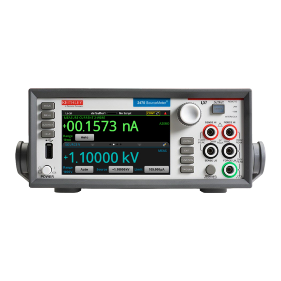
Tektronix KEITHLEY 2470 Quick Start Manual
High voltage sourcemeter
Hide thumbs
Also See for KEITHLEY 2470:
- Reference manual (1125 pages) ,
- User manual (84 pages) ,
- User manual (68 pages)
Table of Contents
Advertisement
Quick Links
Advertisement
Table of Contents

Related Manuals for Tektronix KEITHLEY 2470


Summary of Contents for Tektronix KEITHLEY 2470
- Page 1 Model 2470 High Voltage SourceMeter ® Quick Start Guide...
-
Page 2: Safety Precautions
Safety precautions overvoltages often associated with local AC mains connections. Certain Keithley measuring instruments may be connected to mains. These instruments will be marked as category II The following safety precautions should be observed before using this product and any or higher. - Page 3 Do not touch any object that could provide a current path to the common side of the circuit under The WARNING heading in the user documentation explains hazards that might result test or power line (earth) ground. Always make measurements with dry hands while standing on in personal injury or death.
-
Page 4: Power And Environmental Specifications
Power and environmental specifications CAUTION For indoor use only. 100 V to 240 V 50 Hz to 60 Hz Power supply (autosensing) Carefully consider and configure the appropriate 220 VA Maximum VA output‑off state, source levels, and compliance levels before connecting the instrument to a device that can Maximum 2000 m (6562 ft) above sea level Operating altitude deliver energy. - Page 5 Introduction • Reference Manual: Provides comprehensive information about the features, operation, optimization, maintenance, troubleshooting, and programming commands of the Thank you for choosing a Keithley Instruments product. instrument. The Model 2470 High Voltage SourceMeter instrument is ® a precise, low-noise instrument that combines a stable DC •...
-
Page 6: Unpack And Inspect The Instrument
Unpack and inspect the instrument To unpack and inspect the instrument: 1. Inspect the box for damage. 2. Open the top of the box. 3. Remove the documentation and accessories. 4. Remove the packaging insert. 5. Carefully lift the instrument out of the box. 6. - Page 7 You receive the 2470 with the following accessories: Model 8608 High Performance Test Leads Power line cord Model CS-1616-3 Safety Interlock Mating Connector Crossover cable for TSP-Link or ethernet USB-B-1 USB Cable, Type A to Type B (1 m) Model 2470-903-01 Quick Start Guide (this document; not shown) Safety Precautions (not shown) Refer to the packing list for additional items that might have...
-
Page 8: Connect The Instrument
Connect the instrument • Cover the device under test (DUT) to protect the operator from flying debris in the event of a system or DUT failure. Important test system safety information • Make sure any test fixture connected to the system This product is sold as a stand-alone instrument that may protects the operator from contact with hazardous become part of a system that could contain hazardous... -
Page 9: Install The Instrument
Wiring the interlock NOTE WARNING To keep users safe, always read and follow all safety warnings provided with each of the instruments in your system. The 2470 is provided with an interlock circuit that must be positively activated in order for the high‑voltage Install the instrument output to be enabled. - Page 10 If Interlock is set to Off and the safety interlock signal is not An interlock circuit is provided on the rear panel of the asserted, the following occurs: instrument, as shown in the following figure. This circuit must be closed to enable the 2470 to produce voltages greater •...
- Page 11 When the interlock is asserted, any measurement terminals, To ensure proper interlock operation, the combined including the LO terminals, should be considered hazardous resistance of the external interlock switch and connection voltages, even if they are programmed to a non-hazardous wires must be less than 10 Ω...
-
Page 12: Power On The Instrument
Power on the instrument To connect line power: 1. Make sure the front-panel power switch is in the off (O) The 2470 operates from a line voltage of 100 V to 240 V at position. 50 Hz or 60 Hz. The instrument senses the line voltage and 2. -
Page 13: Overview Of The Front-Panel Options
Overview of the front‑panel options 4. Turn on the instrument by pressing the front panel POWER switch to the on (|) position. The instrument starts. The front panel of the 2470 allows you to set up most instrument functions and features and perform sourcing and measuring operations. -
Page 14: Touchscreen Display Overview
Touchscreen display overview You can use the touchscreen display to set up the instrument and tests. You use the keys and touch capabilities to make selections. To use the touchscreen, select options with your finger. You can also use the navigation control to highlight an item, and then press the control to select it. - Page 15 The bottom half of the touchscreen display contains multiple An example of the SETTINGS swipe screen is shown below. screens that you can swipe to access additional information In the SETTINGS swipe screen shown here, the Auto Zero and settings: feature is turned on.
- Page 16 ENTER and EXIT keys In the GRAPH swipe screen shown here, you can view the measurements as they occur. To see a full-screen graph, The ENTER key selects a highlighted option. In most cases, touch the graph icon on the right side of the swipe screen it opens a menu or dialog box that allows you to make header bar to go to the Graph screen.
-
Page 17: Menu Screen Overview
Menu screen overview From this screen, you can select source, measure, graphing, trigger, scripting, and system setup menus. These menus allow you to choose options to set up your instrument to When you press the MENU key on the front panel, the Menu meet the needs of your applications. -
Page 18: Quick Setup Options
Quick Setup options When you press QUICKSET, the BASIC SOURCE/ MEASURE SETTINGS screen is displayed. From this menu, you can: • Choose the source and measure functions. • Use the Performance slider to select the best balance between measurement resolution and measurement speed. - Page 19 Help FUNCTION You can display help screens for the menu items and The FUNCTION key opens the FUNCTION selection dialog buttons. The help screens give a brief description of box, which allows you to select the source and measure the option that the menu or button sets. To display the functions.
-
Page 20: Connections For Testing
Connections for testing To make connections for testing: 1. Make sure the front-panel power switch is in the off (O) position. The following figure shows the physical connections for the front panel. Note that you must use either the front terminals 2. -
Page 21: Verify Measurement Operation
Verify measurement operation To save the data to a USB flash drive: 1. Insert a USB flash drive into the front-panel USB port. The following steps provide a quick way to verify that the 2. Press the MENU key. instrument is operating correctly. 3. -
Page 22: Why Did My Settings Change
FAQs To view the measurements on the front-panel graph: 1. Press the MENU key. Where can I find updated drivers or firmware? 2. Under Views, select Graph. For the latest drivers and additional support information, see You can swipe and use pinch and zoom to change the view the Keithley Instruments support website. -
Page 23: How Do I Change The Command Set
Next steps How do I change the command set? In addition to the front panel, you can use a remote interface For more information, refer to the Keithley Instruments to set up the instrument. You can choose one of the following website, tek.com/keithley, for support and additional command sets: information about the instrument, including the following... - Page 24 Middle East, Asia, and North Africa Find more valuable resources at TEK.COM Australia* 1 800 709 465 +41 52 675 3777 Copyright © 2019, Tektronix. All rights reserved. Austria 00800 2255 4835 Tektronix products are covered by U.S. and The Netherlands* 00800 2255 4835 foreign patents, issued and pending.
Need help?
Do you have a question about the KEITHLEY 2470 and is the answer not in the manual?
Questions and answers