
Related Manuals for Gree MULTI24HP230V1CO


Summary of Contents for Gree MULTI24HP230V1CO
- Page 1 PTAC DIRECT SALES, INC. 185 S. KIMBALL AVE., SUITE 130 SOUTHLAKE, TX 76092 Change for Life 877.454.7822 Service Manual Models: MULTI18HP230V1CO MULTI24HP230V1CO GREE ELECTRIC APPLIANCES,INC.OF ZHUHAI...
-
Page 2: Table Of Contents
Service Manual Table of Contents Part : Technical Information ................1 1. Summary ..........................1 ........................2 3. Outline Dimension Diagram ................6 4. Refrigerant System Diagram ................7 5. Electrical Part ........................8 5.1 Wiring Diagram.........................8 5.2 PCB Printed Diagram ......................10 6. Function and Control ....................12 Part : Installation and Maintenance... -
Page 3: Part : Technical Information
Service Manual Part : Technical Information 1. Summary Outdoor Unit MULTI18HP230V1CO MULTI24HP230V1CO Technical Information... - Page 4 Service Manual MULTI18HP230V1CO Model Product Code CB228W04100 Rated Voltage 208/230 Power Rated Frequency supply Phases Cooling capacity(max~min) 5280(2051~6155) Heating capacity(max~min) 5570(2500~6624) Cooling Power Input(max~min) 1650 Heating Power Input(max~min) 1640 Cooling Current Input 10.67/10.56 Heating Current Input 6.78/6.10 Rated Power Input 2800 Rated Current 12.48...
- Page 5 Connection Pipe Connection Method Flare Connection Not Additional Gas Connection Pipe Length 16.4 Connection Pipe Gas Additional Charge oz/ft. Outer Diameter of Liquid Pipe1(GREE Allocation) inch (Metric) Outer Diameter of Liquid Pipe2(GREE Allocation) inch (Metric) Outer Diameter of Gas Pipe1(GREE Allocation)
- Page 6 Service Manual MULTI24HP230V1CO Model Product Code CB228W04200 Rated Voltage 208/230 Power Rated Frequency supply Phases Cooling capacity(max~min) 7620(2198~9672) Heating capacity(max~min) 8500(2198~7500) Cooling Power Input(max~min) 2400 Heating Power Input(max~min) 2350 Cooling Current Input 10.65 Heating Current Input 10.43 Rated Power Input...
- Page 7 Connection Pipe Connection Method Flare Connection Not Additional Gas Connection Pipe Length 16.4 Connection Pipe Gas Additional Charge oz/ft. Outer Diameter of Liquid Pipe1(GREE Allocation) inch (Metric) Outer Diameter of Liquid Pipe2(GREE Allocation) inch (Metric) Outer Diameter of Liquid Pipe2(GREE Allocation)
-
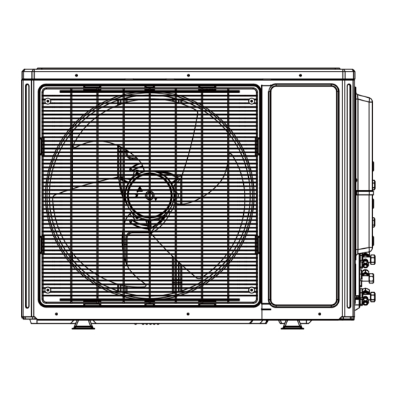
Page 8: Outline Dimension Diagram
Service Manual 3. Outline Dimension Diagram MULTI18HP230V1CO 35 1/8 13 3/7 15 3/5 Unit:inch MULTI24HP230V1CO 13 3/7 35 1/8 17 1/3 38 4/7 Unit:inch Technical Information... -
Page 9: Refrigerant System Diagram
Service Manual 4. Refrigerant System Diagram outdoor indoor filter A heat exchanger filter outdoor heat exchanger 4-way valve B heat exchanger filter high pressure switch Note: Not available for 14K/18K model discharge silencer C heat exchanger discharge temperature sensor filter D heat exchanger gas -liquid separator filter... -
Page 10: Electrical Part
Service Manual 5. Electrical Part 5.1 Wiring Diagram Symbol Symbol Color Symbol Symbol Color Symbol Name White GREEN COMP Compressor Yellow Brown Grouding wire Blue YEGN Yellow/Green Black Violet Orange MULTI18HP230V1CO Technical Information... - Page 11 Service Manual MULTI24HP230V1CO These circuit diagrams are subject to change without notice, please refer to the one supplied with the unit. Technical Information...
-
Page 12: Pcb Printed Diagram
Service Manual 5.2 PCB Printed Diagram MULTI18HP230V1CO Terminal of compressor TOP VIEW Terminal of low-temperature cooling temperature sensor Overload protection terminal of compressor Temperature sensor terminal of outdoor unit High pressure protection terminal Low pressure protection terminal Terminal of outdoor unit Electric heating belt terminal of chassis Terminal of 4-way valve... - Page 13 Service Manual MULTI24HP230V1CO Terminal of compressor TOP VIEW Low pressure protection terminal High pressure protection terminal Overload protection terminal of compressor Temperature sensor terminal of outdoor unit Electric heating terminal of chassis Electric heating terminal of compressor Terminal of outdoor unit...
-
Page 14: Function And Control
Service Manual 6. Function and Control 1 Basic functions of the system 1.1 Cooling Mode 1.1.1 Cooling conditions and process: If the compressor is in stop status and start the unit for cooling operation, when one of the indoor units reaches the cooling operation condition, the unit start cooling operation;... - Page 15 Service Manual 1.3.3 Outdoor fan control in heating mode The outdoor fan starts before 5s of the starting of compressor and then it will run in high speed for 40s; The fan shall run at every speed for at least 80s; When the compressor stops, the outdoor fan stops after 1min.
- Page 16 Service Manual 2.4 Communication malfunction Detection of the quantity of installed indoor units: After 3min of energizing, if the outdoor unit does not receive the communication data of certain indoor unit, the outdoor unit will judge that indoor unit is not installed and will treat it as it is not installed. If the outdoor unit receives the communication data of that indoor unit later, the outdoor unit will treat that unit as it is installed.
-
Page 17: Part : Installation And Maintenance
Service Manual Part : Installation and Maintenance 7. Notes for Installation and Maintenance Safety Precautions: 10. If the power cord or connection wire is not long enough, please get the specialized power cord or connection wire Important! from the manufacture or distributor. Prohibit prolong the wire by yourself. - Page 18 Service Manual Main Tools for Installation and Maintenance 1. Level meter, measuring tape 2. Screw driver 3. Impact drill, drill head, electric drill 4. Electroprobe 5. Universal meter 6. Torque wrench, open-end wrench, inner hexagon spanner 8. Vacuum pump 9. Pressure meter 10.
-
Page 19: Installation Manual
Service Manual 8. Installation Manual Installation procedures Start installation Preparation before installation Read the requirements select installation Prepare tools for electric connection location Select indoor unit Select outdoor unit installation location installation location Install the support of outdoor unit Install wall-mounting frame, drill wall holes (select it according to the actual situation) Connect pipes of indoor... -
Page 20: Electrical Connections
L1 L2 Wrong wire connection may cause malfunction of some The connection pipes and the connectiong wirings of MULTI24HP230V1CO the unit A and unit B must be corresponding to each other respective. The appliance shall be installed in accordance with national wiring regulations. -
Page 21: Installing The Outdoor Unit
Service Manual 8.2 Installing the Outdoor Unit heat pump only) Location Condensation is produced and flows from the outdoor unit when the appliance is operating in the heating mode. In order When mounting the unit on a wall or the roof, make sure the support is not to disturb neighbours and to respect the environment, install a drain fitting and a drain hose to channel the condensate... -
Page 22: Installation Dimension Diagram
30cm or above Space to the cover 30cm or above (Air inlet side) 200cm or above (Air outlet side) MULTI24HP230V1CO 50cm or more Space to the cover 30cm or above Space to the cover 30cm or above (Air inlet side) -
Page 23: Check After Installation
Service Manual Check Items Problems Owing to Improper Installation Is the installation reliable? The unit may drop, vibrate or make noises May cause unsatisfactory cooling (heating) Has the gas leakage been checked? effect Is the thermal insulation of the unit May cause condensation and water dropping sufficient? May cause condensation and water dropping... -
Page 24: Troubleshooting
Service Manual 9. Troubleshooting 1. Requirement of malfunction display When several malfunctions happen at the same time, malfunction codes will be displayed circularly. 2. Malfunction display method (1) Hardware malfunction: it will be displayed immediately, please refer to “Malfunction status sheet”; (2) Operation status: it will be displayed immediately, please refer to “Malfunction status sheet”;... -
Page 25: Malfunction Checking And Elimination
Service Manual Viewing malfunction code through remote controller within Compressor overload protection 200s; displayed directly on nixietube after 200s Wrong connection of communication wire or malfunction of Hardware malfunction electronic expansion valve Detection status of wrong connection of communication wire Operation status or malfunction of electronic expansion valve t c i... - Page 26 Service Manual ● If the resistance of compressor coil is normal? If the isolation of compressor coil with copper pipe is good? ● If the unit is overloaded? If the heat radiation of the unit is good? ● If the refrigerant charge is suitable? Energize the unit Flow chart: Please check:...
- Page 27 Service Manual 2. PFC protection malfunction, capacity charging malfunction Main checking points: If the wiring of the induction is connected well and if the induction is broken; If the mainboard is broken; Flow chart: Start Check if power supply is normal Turn on the unit after power supply Power supply is abnormal?
- Page 28 Service Manual Start Check If the power supply is normal Turn on the unit after the power supply resumes to Power supply is abnormal normal situation Check if the outdoor induction is broken Malfunction is eliminated Replace the outdoor mainboard Installation and Maintenance...
- Page 29 Service Manual 3. Compressor desynchronizing malfunction Main checking points: If the pressure of the system is too high; If the eletric expansion valve is working normally or it is broken; If the radiation of the unit is good; Flow chart: The unit appears desynchronizing as soon as energizing and starting The stop duration of the compressor is longer...
- Page 30 Service Manual Desynchronizing happens during operation Check if fan Replace the fan capacitor Outdoor unit is working? terminal is connected well Improve radiation situation of the unit Unit radiation is good? (such as cleaning Replace the outdoor unit the heat exchanger, improve ventilation Turn on the unit after the power...
- Page 31 Service Manual 4. Compressor overload, diacharge protectionmalfunction Main checking points: If the eletric expansion valve is connected well or it is broken; If there is refrigerant leakage; If the overload protector is broken; Flow chart: Start If the overload protector is connected well? Check the resistance between the two ends of the overload protector in ambient temperature, if the resistance is below 1k...
- Page 32 Service Manual 5. Start failuremalfunction Main checking points: If the connection wire of the compressor is connected properly; If the stop duration of the compressor is sufficient; If the compressor is broken; If the refrigerant charging amount is too much; Flow chart: Energize and start the unit...
- Page 33 Service Manual 6. Temperature sensor malfunction Main checking points: If the temperature sensor is damaged or broken If the terminal of the temperature sensor is loosended or not connected; If the mainboard is broken; Flow chart: Start Check whether the wiring terminal between temperature sensor and controller is loosened or poorly contacted? Insert the temperature...
- Page 34 Service Manual 7. DC fan malfunction Main checking points: If the outdoor fan is blocked by foreign objects; The connection wire of DC fan is connected reliably? If it is loose? Flow chart: Start Turn on the unit Check if the after removing the outdoor fan is blocked by foreign objects...
- Page 35 Service Manual 8. Communication malfunction Main checking points: If the connection wire between the indoor unit and outdoor unit is connected well, if the wires inside the unit is connected well; If the indoor mainboard or outdoor main board is broken; Flow chart: Communication malfunction of some indoor units...
- Page 36 Service Manual All the indoor units appear communication malfunction De-energize,check if the connection wire of indoor and outdoor unit and the wire of the eletric box is connected correctly Reconnect according to Eliminate the malfunction Connected correctly? the wiring diagram De-energize, check if the connection wire between the outdoor mainboard and the filter board according to the wiring diagram...
- Page 37 Service Manual 9. Anti-high temperatureand overload malfunction Main checking points: If the outdoor ambient temperature is within the normal range; If the indoor fan and outdoor fan are running normally; If the indoor and outdoor radiation environment is good; Flow chart: Start It is a normal protection, please If the outdoor ambient temperature...
-
Page 38: Maintenance Method For Normal Malfunction
Service Manual 9.3 Maintenance Method for Normal Malfunction 1. Air Conditioner Can't be Started Up Possible Causes Discriminating Method (Air conditioner Status) Troubleshooting No power supply, or poor After energization, operation indicator isn’t bright wait for power recovery. If not, check power connection for power plug supply circuit and make sure the power plug is connected well. - Page 39 Service Manual 4. ODU Fan Motor Can't Operate Possible causes Discriminating method (air conditioner status) Troubleshooting Connect wires according to wiring diagram to Wrong wire connection, or poor Check the wiring status according to circuit make sure all wiring terminals are connected connection diagram Measure the capacity of fan capacitor with an...
-
Page 40: Exploded View And Parts List
Service Manual 10. Exploded View and Parts List MULTI18HP230V1CO Installation and Maintenance... - Page 41 Service Manual Part Code Description MULTI18HP230V1CO Product Code CB228W04100 Front Grill 01473050 Front Panel Assy 01433069 Chassis Sub-assy 02803280P Drainage Connecter Drainage hole Cap Gas-liquid Separator Assy 07223048 Compressor and Fittings 0010524501G Electric Heater(Compressor) 7651873215 Tube Connector Sub-assy 06643008 Magnet Coil 4300040045 4-Way Valve Assy 03015200001...
- Page 42 Service Manual MULTI24HP230V1CO Installation and Maintenance...
- Page 43 Service Manual Part Code Description MULTI24HP230V1CO Product code CB228W04200 Front Grill 01473050 Cabinet 0143500401P Left Handle 26235401 Front Side Plate 01305086P Electrical Heater (Chassis) 7651000411 Chassis Sub-assy 02803280P Gas-liquid Separator 07223048 Compressor and Fittings 0010524501G Electric Heater(Compressor) 7651873215 Tube Connector Sub-assy...
-
Page 44: Removal Procedure
Service Manual 11. Removal Procedure Warning: Be sure to wait for a minimum of 20 minutes after turning off all power supplies and discharge the refrigerant completely before removal. WHD(18)HP230V1CO Steps Procedure 1.Remove big handle and wire connection cover Before disassembly plate to remove the big handle. - Page 45 Service Manual Steps Procedure 2.Remove top cover top cover right side plate, to remove top cover. 3.Remove grille the grille on the panel. grille 4.Remove panel support, to remove the panel. panel Installation and Maintenance...
- Page 46 Service Manual Steps Procedure 5.Remove right side plate support and guard grille, to remove the right side plate. right side plate 6.Remove guard grille plate to remove guard grille. guard grille 7.Remove left side plate support, to remove the left side plate. left side plate Installation and Maintenance...
- Page 47 Service Manual Steps Procedure 8.Remove condenser support remove the condenser support. condenser support 9.Remove axial fan blade to remove the fan blade. axial fan blade 10.Remove motor and motor support sub-assy pin of leading wire for motor and remove the screws and motor support sub-assy.
- Page 48 Service Manual Steps Procedure 11.Remove electric box sub-assy electric box sub-assy loosen the wire binds, pull out the terminal, lift to remove the electric box sub-assy. 12.Remove PFC electrical inductance and isolation sheet, to remove the PFC electrical inductance. PFC electrical inductance 13.Remove four-way valve sub-assy four-way valve sub-assy...
- Page 49 Service Manual Steps Procedure 14.Remove suction pipe sub-assy Welding cut the welding point jointing the suction pipe sub-assy, compressor and liquid receiver, to remove the suction pipe sub-assy. suction pipe sub-assy 15.Remove liquid receiver receiver and lift to remove the liquid receiver. liquid receiver 16.Remove the isolation sheet assy Remove the screws fixing isolation sheet and...
- Page 50 Service Manual Steps Procedure 17.Remove compressor compressor chassis with spanner, as well as the foot cushion, to remove the compressor. 18.Remove valve support assy valve support assy chassis sub-assy, to remove the valve support assy. 19.Remove EXV assy Welding cut the welding point jointing EXV sub-assy and refrigerant collection pipe, to remove the EXV assy.
- Page 51 Service Manual MULTI24HP230V1CO Steps Procedure 1. Remove valve cover and top panel Twist off the screws used for fixing and valve cover , pull v alve cover up ward to remove it. top panel Remove the 3 screws connecting the top panel with the front panel and the right side plate, and then remove the top panel.
- Page 52 Service Manual Remove the 5 screws connecting the panel with the chassis and the motor support, and then remove the panel. panel 3. Remove right side plate and left side plate right side plate Remove the scre ws connecting the right side plate with the chassis, the valve support and the electric box, and then remove the right side plate assy .
- Page 53 Service Manual 4. Remove fan motor and axial flow blade axial flow blade Remove the nuts fixing the blade and then remove the axial flow blade. fan motor fixing frame Remove the 4 tapping screws fixing the motor; disconnect the leading wire insert of the motor and then remove the motor.
- Page 54 Service Manual 6.Remove soundproof sponge and 4-way valv e assy soundproof sponge Since the piping ports on the soundproof sponge are torn easily, remove the soundproof sponge carefully 4-way valv e assy Discharge the refrigerant completely;unsolder the pipelines connecting the compressor and the condenser assy,and then remove the 4-way valve assy.
- Page 55 Service Manual 8. Remove Cut off Valve and Valve Support Remove the 2 bolts fixing the valve subassemblies. Unsolder the welding joint connecting the gas valve and the return air pipe. Remove the gas valve. (Note: When unsoldering the soldering joint, wrap the gas valve with wet cloth completely to avoid damage to the valve caused by high temperature.) Valve Support...
- Page 56 Service Manual condenser sub-assy 11.Remove condenser sub-assy Remove the chassis sub-assy and condenser sub-assy. chassis sub-assy Installation and Maintenance...
-
Page 57: Appendix
Service Manual Appendix: Appendix 1: Reference Sheet of Celsius and Fahrenheit Conversion formula for Fahrenheit degree and Celsius degree: Tf=Tcx1.8+32 Set temperature Fahrenheit Fahrenheit Fahrenheit display Fahrenheit display Fahrenheit display Fahrenheit Celsius Celsius Celsius temperature temperature temperature 60.8 69/70 69.8 78/79 78.8 62/63... -
Page 58: Appendix 3: Pipe Expanding Method
Service Manual Appendix 3: Pipe Expanding Method Pipe Note: Pipe cutter expand the pipe according to the following steps: Leaning Uneven Burr A:Cut the pip Pipe B:Remove the burrs Shaper Downwards C:Put on suitable insulating pipe Union pipe D:Put on the union nut Pipe the union nut on the pipe. -
Page 59: Appendix 4: List Of Resistance For Ambient Temperature Sensor
Service Manual Appendix 4: List of Resistance for Temperature Sensor Resistance Table of Ambient Temperature Sensor for Indoor and Outdoor (15K) Temp( Temp( Temp( Temp( 138.1 18.75 3.848 1.071 128.6 17.93 3.711 1.039 121.6 17.14 3.579 1.009 16.39 3.454 0.98 108.7 15.68 3.333... - Page 60 Service Manual Resistance Table of Tube Temperature Sensors for Indoor and Outdoor (20K) Temp( Temp( Temp( Temp( 181.4 25.01 5.13 1.427 171.4 23.9 4.948 1.386 162.1 22.85 4.773 1.346 153.3 21.85 4.605 1.307 20.9 4.443 1.269 137.2 4.289 1.233 129.9 19.14 4.14 1.198...
- Page 61 Service Manual Resistance Table of Discharge Temperature Sensor for Outdoor(50K) Temp( Temp( Temp( Temp( 853.5 18.34 4.75 799.8 93.42 17.65 4.61 89.07 16.99 4.47 703.8 84.95 16.36 4.33 660.8 81.05 15.75 4.20 620.8 77.35 15.17 4.08 580.6 73.83 14.62 3.96 548.9 70.5 14.09...
- Page 62 JF00302123 PTAC DIRECT SALES, INC. 185 S. KIMBALL AVE., SUITE 130 SOUTHLAKE, TX 76092 877.454.7822 GREE_MULTI21+_C_SERVICE_18-24MBH_070717...
Need help?
Do you have a question about the MULTI24HP230V1CO and is the answer not in the manual?
Questions and answers
my ac shuts off and doesn't come back on is there an error code on the unit
Yes, the Gree MULTI24HP230V1CO air conditioner displays malfunction codes when it shuts off due to an error. Hardware and operation errors are displayed immediately, while other malfunctions are shown after the compressor stops for 200 seconds.
This answer is automatically generated
why won't the dampers close on the indoor wall units.