
Related Manuals for KROHNE DR 400 Series


Summary of Contents for KROHNE DR 400 Series
- Page 1 DRX400 / X500 Supplementary Instructions DR3500 / DR5400 DR6400 / DR6500 DR7400 / DR7500 Safety manual © AMETEK Drexelbrook - DRx400-x500-PM - English – SIL2/3 06-29-21 – Issue 2...
-
Page 2: Table Of Contents
CONTENTS DRX400 / X500 1 Introduction 1.1 Scope of the document..................... 4 1.2 Revision history ........................ 4 1.3 Type code for devices that can operate in SIL mode ............5 1.4 Device description ......................6 1.5 Related documentation ....................7 1.6 Terms and definitions....................... - Page 3 CONTENTS DRX400 / X500 4.3 How to check measurement accuracy before operation in SIL mode ......24 4.3.1 General notes........................24 4.3.2 Measurement accuracy check (in process conditions) ............24 4.4 Operation modes and proof tests................... 25 4.5 How to reset the fail-safe flags..................28 4.6 Troubleshooting......................
-
Page 4: Introduction
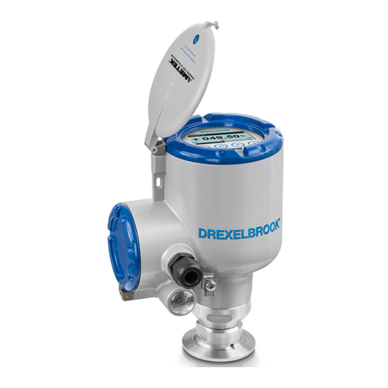
INTRODUCTION DRX400 / X500 1.1 Scope of the document This document supplies functional safety data for the devices that follow: • DRx400: DR5400, DR6400 and DR7400 - 24 GHz FMCW radar level transmitters • DRx500: DR3500, DR6500 and DR7500 - 80 GHz FMCW radar level transmitters This data agrees with the IEC 61508 standard (document [N2]) if the device operates in SIL mode. -
Page 5: Type Code For Devices That Can Operate In Sil Mode
INTRODUCTION DRX400 / X500 1.3 Type code for devices that can operate in SIL mode The model name for the level transmitter and its options are identified by the DRxxxx type code on the device nameplate. The type code is a series of alphanumeric characters (0...9 and A...Z). Do a check of the device nameplate to make sure that device has the correct options for functional safety. -
Page 6: Device Description
INTRODUCTION DRX400 / X500 Code Description Applicable options for SIL devices Cable entry / cable gland — Display Display - documentation language — Enhanced functions opqrstuvw All other device descriptors — Table 1-3: Applicable options for SIL devices 1.4 Device description A device that operates in SIL mode is a functionally safe level transmitter. -
Page 7: Related Documentation
INTRODUCTION DRX400 / X500 1.5 Related documentation [N1] The applicable handbook for the DR3500, DR5400, DR6400, DR6500, DR7400 or DR7500. Refer to the latest edition. [N2] IEC 61508-1 to 7:2010 Functional safety of electrical / electronic / programmable electronic safety- related systems [N3] NAMUR Recommendation NE 043 Standardization of the Signal Level for the Failure Information of... - Page 8 INTRODUCTION DRX400 / X500 Systematic Capability Measure (given as a scale of SC 1 to SC 3) of the confidence that the systematic safety integrity of an element agrees with the conditions of the specified SIL (related to the safety function of an element), when the element is applied in accordance with the instructions.
-
Page 9: Specification Of The Safety Function
SPECIFICATION OF THE SAFETY FUNCTION DRX400 / X500 2.1 Preconditions The device must be operated in the process and ambient conditions given in the handbook (document [N1]) of the device. Other conditions must be obeyed for safety applications. For more data refer to Safety application conditions (SAC) on page 12. -
Page 10: Current Output
SPECIFICATION OF THE SAFETY FUNCTION DRX400 / X500 2.2.2 Current output The device sends a current output signal that agrees with the correct measured value. This output has these properties: • A current that is related to the correct measured value in an interval that is equal to or less than the Fault Response Time. -
Page 11: Fault Response Time
SPECIFICATION OF THE SAFETY FUNCTION DRX400 / X500 2.2.3 Fault response time If the device detects a failure, then it changes the current output to the low or high failure current value in an interval equal to or less than the fault response time. The maximum fault response time is 90 seconds. -
Page 12: Safety Application Conditions (Sac)
SPECIFICATION OF THE SAFETY FUNCTION DRX400 / X500 2.3 Safety application conditions (SAC) WARNING! The device must have the applicable options and settings for the application. The ambient and process conditions must agree with the technical data given in the handbook (document [N1]) and this document (safety manual). -
Page 13: Electrical Connection
SPECIFICATION OF THE SAFETY FUNCTION DRX400 / X500 2.3.3 Electrical connection • Only connect the device to PELV circuits that agree with International Standard IEC 61140. • Wait for 120 seconds after you de-energize the device before you connect the electrical cables again. -
Page 14: Operation Modes
SPECIFICATION OF THE SAFETY FUNCTION DRX400 / X500 2.4 Operation modes 2.4.1 SIL mode The device operates with a safety function. If the safety function detects a failure, it will send a failure current signal that gives a warning that the safety function cannot continue to operate correctly. -
Page 15: Operation
OPERATION DRX400 / X500 3.1 Operation in SIL mode 3.1.1 General notes The device must have the SIL option to operate in SIL mode and use the safety function. If you sent an order for a device with a SIL option, then SIL mode activation is unlocked and the safety function is available. - Page 16 OPERATION DRX400 / X500 Part 2: Current output check • Connect an ammeter to the circuit. • Push a button on the keypad. The device will do a check of the current output. • Look at the current values on the ammeter display screen. The current output automatically changes in this sequence at intervals of 1 second: 3.5 mA, 4 mA, 6 mA, 8 mA, 10 mA, 12 mA, 14 mA, 16 mA, 18 mA, 20 mA and 21.5 mA.
- Page 17 OPERATION DRX400 / X500 Figure 3-1: How to lock the device configuration in SIL mode You will see the screens that follow after you connect the display module to the electronics block: Figure 3-2: Device operation in SIL mode 1 SIL mode symbol (this symbol is only shown in SIL mode) www.drexelbrook.com DRx400-x500-PM - English –...
-
Page 18: How To Change The Configuration Of A Device Operated In Sil Mode
OPERATION DRX400 / X500 3.2 How to change the configuration of a device operated in SIL mode 3.2.1 General notes It is not permitted to change the configuration of a device in SIL mode. If it is necessary for the device to use a new parameter in SIL mode, you must put the device in non-SIL mode to change the configuration. -
Page 19: Error Conditions
OPERATION DRX400 / X500 • Look at the current values on the ammeter display screen. The current output automatically changes in this sequence at intervals of 1 second: 3.5 mA, 4 mA, 6 mA, 8 mA, 10 mA, 12 mA, 14 mA, 16 mA, 18 mA, 20 mA and 21.5 mA. -
Page 20: Parameter Types
OPERATION DRX400 / X500 3.4 Parameter types 3.4.1 Safety-critical parameters You cannot change safety-critical parameters. The menu items for these parameters are automatically set, locked and show a padlock symbol adjacent to the related parameters in the device menu. CAUTION! Safety-critical parameters for SIL mode do not always have the same values as the values set in non-SIL mode. -
Page 21: Non-Sil Parameters
OPERATION DRX400 / X500 Menu Menu item Safety-relevant values Description C1.2 Tank Height min-max: Tank height cannot be more than 18 m / 59 ft. 0.0...18.0 m / 0.0…59.0 ft C2.3 Epsilon R Product min-max: 1.5...20.0 C4.1.1 Current Output 1 Variable Level, Distance, Sensor "Reflection"... -
Page 22: Homogeneous Redundancy
OPERATION DRX400 / X500 3.5 Homogeneous redundancy 3.5.1 Description of a homogeneously redundant system If two devices with the same parameters are used to measure a level (or a distance), then they can be used as a SIL 3 safety function. The two devices take the same measurements. The safety function data from each device are sent to one or more logic solvers. -
Page 23: How To Estimate The Effect Of Common Cause Failures
OPERATION DRX400 / X500 3.5.2 How to estimate the effect of common cause failures An estimate of the effect of common cause failures (random hardware failures and systematic failures) must agree with the methods given in Annex D of International Standard IEC 61508-6 (reference document [N2]). -
Page 24: Service
SERVICE DRX400 / X500 4.1 Maintenance Obey the maintenance instructions given in the handbook (document [N1]). 4.2 Availability of services The manufacturer offers a range of services to support the customer. These services include repair, maintenance, technical support and training. INFORMATION! For more data, speak or write to your local sales office. -
Page 25: Operation Modes And Proof Tests
SERVICE DRX400 / X500 • End of the procedure. The tolerance is ±2 mm / 0.08¨ in reference conditions. If the difference between ref_pt1 and meas_pt1 and between ref_pt2 and meas_pt2 agrees with the safety loop tolerance, then the results of the test are satisfactory. If the 2 values do not agree with the tolerance, then the results of the test are unsatisfactory. - Page 26 SERVICE DRX400 / X500 CAUTION! • Proof tests done by the customer must be equivalent or more difficult than the tests given in this section. • Keep a report of each proof test. These reports must include the date, the tests results (performance of the safety function or faults found), a list of approved personnel who did the test and the report revision number.
- Page 27 SERVICE DRX400 / X500 PART 2: How to check the measurements (example procedure given) • Find the data for the 4 mA and the 20 mA settings in the SIS specification. • Push [^] to start. • Fill the tank to the maximum level (without overfill). Measure the level of the product in the tank with an approved level measurement device (reference device).
-
Page 28: How To Reset The Fail-Safe Flags
SERVICE DRX400 / X500 4.5 How to reset the fail-safe flags If a permanent failure is detected, then you must restart the device manually. The device display screen displays the text that follows: SIL locked! Press key to start test Push a button to go to the procedure to restart the device. -
Page 29: Technical Data
TECHNICAL DATA DRX400 / X500 5.1 Characteristics for the device safety function Version DRx400 DRx500 non-Ex / Ex i Ex d non-Ex / Ex i Ex d Electronic revision 2.1.1 Device type Type B system Systematic capability Safety integrity level Single channel (HFT = 0) SIL2 Homogeneously redundant... -
Page 30: Assumptions
TECHNICAL DATA DRX400 / X500 5.3 Assumptions FMEDA is applicable for the conditions that follow: • Use of the device agrees with its design and performance characteristics. This includes ambient and process conditions. • Installation of the device must agree with the instructions and the requirements of the application. -
Page 31: Support For Sil-Approved Devices
TECHNICAL DATA DRX400 / X500 Figure 5-1: Measuring accuracy in relation to level X: level / [mm] or [inches] Y: measuring accuracy / [%] 1 Limits for a non-SIL device (undamaged device, tested) 2 SIL limits (monitored limits) 3 Typical level measurements in process conditions with parasitic signals etc. The calculation also includes the possible effects of: •... - Page 32 AMETEK Drexelbrook makes no warranty of any kind with regard to the material contained in this manual, including, but not limited to, implied warranties or fitness for a particular purpose. Drexelbrook shall not be liable for errors contained herein or for incidental or consequential damages in connection with the performance or use of material.
Need help?
Do you have a question about the DR 400 Series and is the answer not in the manual?
Questions and answers