Table of Contents
Advertisement
Quick Links
Advertisement
Table of Contents

Related Manuals for Apelson UBGHJ611


Summary of Contents for Apelson UBGHJ611
- Page 1 UBGHJ611 UBGJ612W UBGHJ614...
- Page 2 [02] x 1 [03] x 1 [01] x 1 [04] x 1 [05] x 1 1 : 1 [06] x 1 set [09] x 4 [07] x 1 [10] x 4 [12] x 1set [08] x 4 [11] x 1...
- Page 3 UBGHJ611 UBGJ612W UBGHJ614 Built-in Gas Hob Installation...
- Page 4 Let's get started... started... Getting Before you start Safety detail... more Product functions Operation Care and maintenance Troubleshooting Recycling and disposal Technical and legal information Appendix Installation...
-
Page 5: Getting Started
Getting Started... Before you start Safety... - Page 6 Before you start Before you start To avoid the risks that are always present when you use an electrical appliance it is important that this appliance is installed correctly and that you read the safety instructions carefully to avoid misuse and hazards. please keep this instruction booklet for future reference and pass it on to any future owners.
- Page 7 Safety Safety These instructions are for your safety. Please read through them thoroughly prior to installation and retain them for future reference. 5 WARNING: The connection of the hob to the gas network or gas cylinder must be made by means of a rigid copper or steel pipe with fittings complying with local regulations.
- Page 8 Safety 5 Children shall not play with the appliance. 5 Cleaning and user maintenance shall not be made by children unless they are older than 8 years and supervised. 5 Keep the appliance and its cord out of reach of children less than 8 years.
- Page 9 Safety 5 Do not store detergents or flammable materials beneath the hob 5 Do not leave hot oils or fats unattended as they may catch light. 5 The Manufacturer declines all liability for personal or material damage as a result of misuse or incorrect installation of this appliance.
- Page 10 Safety 5 Never use cookware with a diameter larger then the diameter of the cooking zone. 5 This appliance shall be installed in accordance with the regulations in force and only used in a well ventilated space. 5 Read the instructions before installing or using this appliance. 5 CAUTION: The use of a hob guard is not permitted with this appliance.
-
Page 11: Table Of Contents
more detail... Product functions Operation Care and maintenance Troubleshooting Recycling and disposal Technical and legal information... -
Page 12: Product Functions
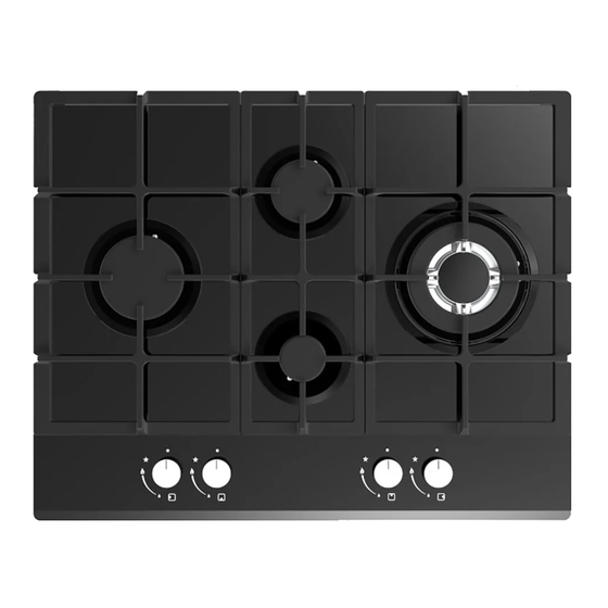
Operation Product functions • 4 x Burners: Four zones of cooking. • Flame safety device (FSD): Stops the gas supply to the gas hob when the flame goes out • auto - ignition • LPG conversion kit supplied. Control elements Reference Description Qty Reference... -
Page 13: Operation
Operation Operation Use of the burners Caution • If there is no electric current you can light the burners with piezo electric spark gas ignitor. • The burners can only be lit with safety thermocouples when the knob is on MAXIMUM. On the control panel (fig.4) to the left of every knob there is a diagram t indicate the burner to which the knob in question refers. - Page 14 Operation NOTE: > The use of a gas cooking appliance produces heat and humidity in the place where it is installed. Therefore, you need to ensure the place is well ventilated, keeping the > natural ventilation openings clear and using a mechanical ventilation device/ flue or electric fan Intensive or prolonged use of the appliance may require additional >...
-
Page 15: Care And Maintenance
Care and maintenance Appliance cleanliness Warning Always switch off the electricity supply before performing maintenance work. In the event of a fault, FUSE contact customer services. Caution • Use soapy water and a cloth for cleaning. Never use abrasive powders. •... - Page 16 Care and maintenance Replacement of parts Warning Always switch off the electricity supply before performing maintenance work. In the event of a fault, FUSE contact customer services.
-
Page 17: Troubleshooting
Troubleshooting Troubleshooting The following circumstances may not be a problem. Do not contact the If your appliance is still not functioning properly after making the above checks, please contact customer services. 1. C heck that the mains supply has not been switched off. 2. - Page 18 Technical and legal information Technical data Power Supply V/Hz 220-240 Vac 50/60Hz G20-20mbar Gas Pressure mbar G30-28~30/37mbar External Dimensions HxDxW mm 110x510x640 Injector Table Destination: GB Gas Category: II 2H3 +(G20 20mbar, G30 28-30/37mbar) NG (G20 20mbar) LPG(G30 28~30/37mbar) Injector Dia. (mm) and kW Injector Dia.
-
Page 19: Technical And Legal Information
Technical and legal information All installation work must be carried out by a Before connecting the mains supply ensure that the mains voltage corresponds to the voltage on the rating plate inside the cooker hood. Warning: THIS APPLIANCE MUST BE EARTHED. Mains Supply could be connected to the Mains Voltage by Direct Connection DOUBLE POLE SWITCHED... - Page 20 Technical and legal information Electrical Requirements Any permanent electrical installation must comply with the latest I.E.E. Regulations and local electricity company regulations. For roll of the National Inspection Council for Electrical Installation Contracting (NICEIC) should undertake the electrical installation. Electrical Connection Before connecting the mains supply ensure that the mains voltage corresponds to the voltage on the rating plate inside the appliance.
- Page 21 Technical and legal information Installation Guidelines Gas Supply Requirements (UK and ROI) This installation must comply with the Gas Safety Regulations 1984. The connection to the gas supply must comply with all current regulations in force. We are not legally able to offer advice on the installation of gas appliances to non Gas Safe registered personnel.
- Page 22 Technical and legal information Gas connection [11] [11] x1set Changing the nozzles Caution The hob installation and burner changes must be carried out by a competent person. ie a Gas Safe NOTE: The LPG nozzles are provided in a separate bag marked “LPG” and if they are changed and the natural gas jets retained then the label should be changed to “NATURAL”.
- Page 23 Technical and legal information Regulation of burners Regulation of burners Caution The regulation described can only be carried out with burners that use methane gas and city gas (where available), whereas the screw must be fully tightened in a clockwise direction on burners using liquid gas. Regulation of the “mINImUm”...
- Page 24 Technical and legal information The Manufacturer has a policy of continuous product improvement, it necessary without prior warning.
- Page 25 Appendix...
- Page 26 Installation Clearance Warning Good ventilation is required around the appliance for easier dissipation of heat and low power consumption. The gap between the hob and any cupboard above it should be at least 750mm. 750mm 750mm At least 300mm 60mm At least 300mm...
- Page 27 Installation [10] x 1 Cut out worktop to the template dimensions with suitable equipment and seal the cut edge with appropriate sealant. [06] x 1 [06] Stretch out the supplied seal along the underside edge of the hob, ensuring the ends overlap.
- Page 28 Installation 30mm 40mm [09] [07] [07] x 4 [09] [07] [09] x 4 Note: The images above are a guide only. Note: For electrical connection see Technical and legal information section...
- Page 29 Notes...
- Page 32 Apelson Appliances UK Ltd Unit 3 Normandy Landings Pope Street Castleford WF6 2AG United Kingdom 2531-20 Pin code:2531CT-0059 UBGHJ611 UBGJ612W UBGHJ614 20201211...
Need help?
Do you have a question about the UBGHJ611 and is the answer not in the manual?
Questions and answers