Table of Contents

Related Manuals for Jet JWBS-14OS-M


Summary of Contents for Jet JWBS-14OS-M
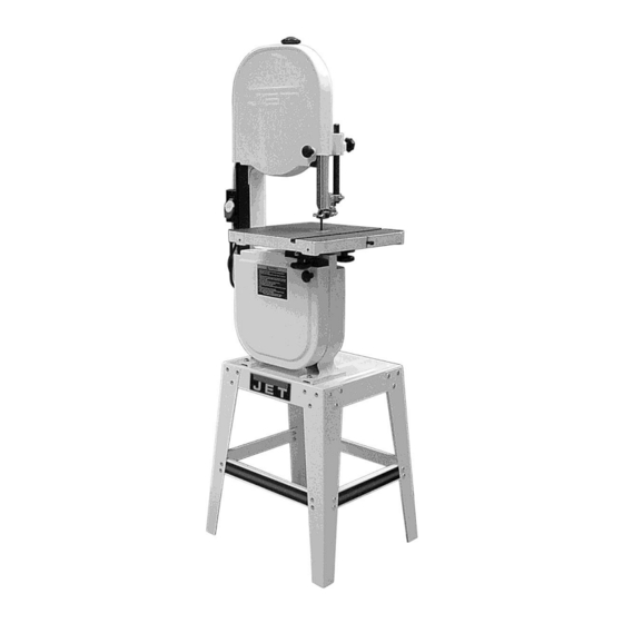
- Page 1 Operating Instructions and Parts Manual 14-inch Woodworking Band Saw Model: JWBS-14OS 427 New Sanford Road LaVergne, Tennessee 37086 Part No. M-708113A Ph.: 800-274-6848 Revision C2 02/2014 Copyright © 2014 JET www.jettools.com...
-
Page 2: Warranty And Service
Accessories; Shop Tools; Warehouse & Dock products; Hand Tools NOTE: JET is a division of JPW Industries, Inc. References in this document to JET also apply to JPW Industries, Inc., or any of its successors in interest to the JET brand. -
Page 3: Table Of Contents
Open Stand Assembly (JWBS-14OS Band Saw) ................... 23 Electrical Connections ..........................24 The specifications in this manual are given as general information and are not binding. JET reserves the right to effect, at any time and without prior notice, changes or alterations to parts, fittings, and accessory... -
Page 4: Warnings
5. Do not use this band saw for other than its intended use. If used for other purposes, JET disclaims any real or implied warranty and holds itself harmless from any injury that may result from that use. - Page 5 19. Provide for adequate space surrounding work area and non-glare, overhead lighting. 20. Keep the floor around the machine clean and free of scrap material, oil and grease. 21. Keep visitors a safe distance from the work area. Keep children away. 22.
-
Page 6: Specifications
Specifications Model Number ..........................JWBS-14OS Stock Number ........................... 708113A Cutting Capacity (height/in.) .......................... 6 Cutting Capacity (width/in.) ........................13-1/2 Minimum Blade Width (in.) ......................... 1/8 Maximum Blade Width (in.) ........................3/4 Blade Length (in.) ..........................93-1/2 Blade Speed (SFPM) ..........................3000 Table Size (in.) ............................. -
Page 7: Shipping Contents
Shipping Contents Contents of the Carton 01 – Body Assembly (1) 03 – Table (1) 04 – Trunnion Support Bracket (1) 05 – Motor (1) 06 – Switch Box (1) 10 – Upper Support Bracket Post (1) 11 – Lower Support Bracket Post (1) 12 –... -
Page 8: Hardware Bag For Stand Assembly
Hardware Bag for Stand Assembly Stand 01 – Carriage Bolt M8x16 (40) Referring to Figure 1. 02 – Serrated Hex Flange Nut M8 (40) 1. Assemble the legs (A) to the table (B). Each leg requires 6 ea M8 x 16 carriage bolts (C) and 6 ea M8 flange nuts. -
Page 9: Mounting Bandsaw To Table
(A) and place onto the stand top (B). 3. Align the two mounting holes on the motor Be sure front of saw (with JET logo) faces with the slot and hole on the casting (C and stand front (JET logo). -
Page 10: Mounting The Switch
5. Standing on the right side of the band saw (Figure 2), pull the motor towards you. 6. Place the belt (C, Fig. 5) around the wheel pulley (B, Fig. 5) and motor pulley (A, Fig. 5). 7. Standing on the right side of the band saw, push the motor away to put tension on the belt. -
Page 11: Upper Blade Guard Assembly
screws flat Upper Blade Guard Assembly washers (B). Referring to Figure 8: Attach the trunnion support bracket (G) to the saw base (E) with two M8x30 hex cap Secure the upper wheel blade guard (A) to the screws (J) and two M8 lock washers (K). upper support bracket post (B) with two each Thread the M8 hex nut (U) approximately M6x10 hex cap screws (C) and M6x16 flat... -
Page 12: Grounding Instructions
grounded outlet is not available. The temporary Grounding Instructions adapter should only be used until a properly grounded outlet can be installed by a qualified This Band Saw must be electrician. This adapter is not applicable in grounded while in use to protect the operator Canada. -
Page 13: Extension Cords
Use only three wire extension cords that have listed plug suitable for 230V operation, as shown three-prong grounding plugs and three-pole in Figure 13. Contact your local authorized JET receptacles that accept the tool’s plug. service center or qualified electrician for proper procedures to install the plug. -
Page 14: Adjustments
Adjustments Unplug the machine from the power source before making any repairs or adjustments. Failure to comply may cause serious injury. Tilting the Table 1. Loosen front rear lock knobs (Figure 14). 2. Tilt table up to 45 degrees to the right or up to 10 degrees to the left. -
Page 15: Adjusting Blade Tension
7. Guide new blade through table slot. Place blade in upper and lower blade guides. Note: The blade teeth should face the operator, and they should point down toward the table. 8. Place blade in the middle of the upper and lower wheel. -
Page 16: Adjusting Upper Blade Guide Assembly
Adjusting Upper Blade Guide Assembly In Figure 19, the blade guard has been removed for clarity. Never operate the Band Saw without all guards in place and in working order. Referring to Figure 19: 1. Disconnect machine from power source. 2. -
Page 17: Optional Accessories
Optional Accessories 708717A JRB-14A Riser Block Kit Increases depth of cut from 6" maximum to 12" maximum. Includes 6" cast block, long frame bolt, front and back blade guards, 105” blade, and mounting instructions with parts list. 708716 JMG-14 Miter Gauge Assembly For straight and angle cutting. -
Page 18: Troubleshooting Jwbs-14Os Band Saw
Troubleshooting JWBS-14OS Band Saw Trouble Probable Cause Remedy Saw unplugged. Check all plug connections. Saw stops or will not Fuse blown, or circuit breaker tripped. Replace fuse, or reset circuit breaker. start. Cord damaged. Replace cord. Check blade with square and adjust Table stop not adjusted correctly. -
Page 19: Body Assembly (Jwbs-14Os Band Saw)
Body Assembly (JWBS-14OS Band Saw) Index No. Part No. Description Size 1 ....JWBS14OS-101 ..Base ......................1 2 ....990180 ..... Hex Cap Screw ............ M16x55 ....... 1 3 ....TS-155010 ....Flat Washer ............M16 ......2 4 .... - Page 20 Body Assembly (JWBS-14OS Band Saw) Index No. Part No. Description Size 51 ..... PWBS14-136 ... Stud Latch ....................2 55 ..... TS-1533042 ..... Pan Head Screw ..........M5x12 ......2 56 ..... 150079 ..... Catch ......................2 57 ..... 150054 ..... Locating Bolt .................... 2 58 .....
- Page 21 Body Assembly (JWBS-14OS Band Saw) Index No. Part No. Description Size 113 ... TS-1540061 ..... Hex Nut* ............... M8 ....... 1 115 ... TS-1504051 ..... Socket Head Cap Screw* ........M8x25 ......2 117 ... TS-1550061 ..... Flat Washer* ............M8 ....... 2 118 ...
- Page 22 Body Assembly (JWBS-14OS Band Saw)
-
Page 23: Open Stand Assembly (Jwbs-14Os Band Saw)
3 ....612050W ....Support Plate (long) ................. 2 4 ....612051W ....Support Plate (short) ................2 5 ....JWBS14OS-205 ..JET Logo Label ..................1 6 ....991516 ..... Carriage Bolt** ............. M8x16 ....... 40 7 .... -
Page 24: Electrical Connections
Electrical Connections...
Need help?
Do you have a question about the JWBS-14OS-M and is the answer not in the manual?
Questions and answers