Table of Contents
Advertisement
This .pdf document is bookmarked
Operating Instructions and Parts Manual
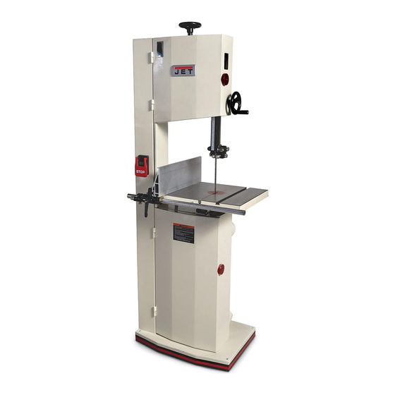
14-inch Woodworking Band Saw
Model JWBS-14SF
WALTER MEIER (Manufacturing) Inc.
427 New Sanford Road
LaVergne, Tennessee 37086
Part No. M-714500
Ph.: 800-274-6848
Revision A 06/2013
www.waltermeier.com
Copyright © 2013 Walter Meier (Manufacturing) Inc.
Advertisement
Table of Contents

Related Manuals for Jet JWBS-14SF


Summary of Contents for Jet JWBS-14SF
- Page 1 This .pdf document is bookmarked Operating Instructions and Parts Manual 14-inch Woodworking Band Saw Model JWBS-14SF WALTER MEIER (Manufacturing) Inc. 427 New Sanford Road LaVergne, Tennessee 37086 Part No. M-714500 Ph.: 800-274-6848 Revision A 06/2013 www.waltermeier.com Copyright © 2013 Walter Meier (Manufacturing) Inc.
-
Page 2: Warranty And Service
Walter Meier Authorized Service Centers can authorize warranty repair, assist you in obtaining parts, or perform routine maintenance and major repair on your JET® tools. For the name of an Authorized Service Center in your area call 1-800-274-6848. -
Page 3: Table Of Contents
15.0 Replacement parts ............................26 15.1.1 JWBS-14SF – Upper Wheel Assembly – Exploded View................. 27 15.1.2 JWBS-14SF – Lower Wheel & Motor Assembly – Exploded View ............28 15.1.3 JWBS-14SF – Table and Miter Gauge Assembly* – Exploded View ............29 ... -
Page 4: Safety Warnings
12. Direction of feed: Feed work into a blade or cutter against the direction of rotation of the blade or cutter only. 13. Maintain proper adjustment of blade tension, blade guides, and thrust bearings. 3.0 Safety warnings 14. Adjust upper blade guides to just clear 1. -
Page 5: About This Manual
This manual is provided by Walter Meier (Manufacturing) Inc. covering the safe operation and maintenance procedures for a JET Model JWBS-14SF Band Saw. This manual contains instructions on installation, safety precautions, general operating procedures, maintenance instructions and parts breakdown. Your machine has been designed and constructed to provide years of trouble-free operation if used in accordance with the instructions as set forth in this document. -
Page 6: Features And Terminology
5.0 Features and Terminology Figure 1 1. Upper wheel 21. Blade tracking knob 2. Tracking window 22. Blade tension handle 3. Guide post handwheel 23. I.D. label 4. Cutting height scale 24. Column 5. Guide post 25. 90-degree stop 6. Upper blade guides 26. -
Page 7: Specifications
6.0 Specifications Model number ............................. JWBS-14SF Stock number .............................. 714500 Motor and electricals: Motor type ............... totally enclosed fan cooled, induction, capacitor start Horsepower ..........................1.75 HP (1.3kW) Phase ................................ single Voltage ........................115/230V (prewired 115V) Cycle ................................60Hz Listed FLA (full load amps) ........................15/7.5 A Starting amps ............................ -
Page 8: Base Hole Centers - Jwbs-14Sf
The specifications in this manual were current at time of publication, but because of our policy of continuous improvement, Walter Meier (Manufacturing) Inc., reserves the right to change specifications at any time and without prior notice, without incurring obligations. 6.1 Base Hole Centers – JWBS-14SF Figure 2... -
Page 9: Setup And Assembly
Read and understand all instructions before attempting assembly or operation of band saw. Failure to comply may cause serious injury. 7.0 Setup and assembly 7.1 Unpacking 1. Remove all contents from shipping carton. Do not discard any shipping material until band saw is assembled and running satisfactorily. -
Page 10: Dust Collection
The JWBS-14SF band saw is rated at 115/230V power, and is pre-wired for 115 volt. The band saw Check with qualified comes with a plug designed for use on a circuit... -
Page 11: Voltage Conversion
3. Grounded, cord-connected tools intended for that is inaccessible to children and others not use on a supply circuit having a nominal rating qualified to use the tool. between 150 - 250 volts, inclusive: This tool is intended for use on a circuit that has an outlet that looks like the one illustrated in D, Figure 5. -
Page 12: Fence Fine Adjust
3. Blade should be fully tensioned (see section 8.10). 4. Place a long straightedge flush against blade, making sure it contacts both front and back of blade. (Do not deflect blade by pushing into it.) See Figure 10. Figure 8 – horizontal position 8.3 Fence fine adjust Refer to Figure 9. -
Page 13: Table Tilt
2. If adjustment is needed, loosen the hex nuts release handle making sure it seats itself on on one of the two adjustment screws (E, pin. Figure 12) and turn the adjustment screw to bring fence in line with miter slot. 3. -
Page 14: Installing/Changing Blades
The JWBS-14SF band saw is designed for blades from 1/8” to 3/4” wide. Refer to Figures 16,17,18. 1. Disconnect machine from power source. -
Page 15: Blade Tracking
4. Open upper door. 5. Rotate tension handwheel (A, Figure 20) until scale pointer (B) indicates width of installed blade. TIP: Use the band saw’s gauge setting initially. As you become familiar with the machine and with different properties of band saw blades, you may find it necessary to change blade tension from initial setting. -
Page 16: Overview: Bearing Adjustments
8.12 Overview: Bearing adjustments blade’s gullet (curved area at base of tooth). See Figure 24. Thrust (back support) bearings are located behind the saw blade and provide support to the back of the blade when the saw is in operation. Guide bearings are located on either side of the saw blade and provide stability for the blade when the saw is in operation. -
Page 17: Lower Blade Guides
8.15 Lower blade guides 4. Tighten lock knob (M). Refer to Figure 26. 8.17 Guide post parallelism 1. Disconnect band saw from power source. The guide post should be parallel to blade 2. Open lower door and swing lower guard out of throughout vertical travel of the guide post;... -
Page 18: Brushes
Figure 28 Figure 30 9.0 Operating controls 9.1 Start/Stop Refer to Figure 31. Press green START button to start saw. Press red paddle button to stop. After machine is shut off, allow wheels and blade to come to a complete stop before opening guards/doors, making Figure 29 adjustments, or leaving the area. -
Page 19: Ripping
10.2 Ripping guide bearings and thrust bearings are set in proper relation to blade. Ripping is cutting lengthwise down the workpiece, 2. Adjust guide post so that guide bearings are along the grain of wood. See Figure 32. Always just above workpiece (about 1/8”) allowing use a push stick or similar device when ripping minimum exposure to blade. -
Page 20: Blade Lead
11.0 Maintenance Before doing maintenance on the machine, disconnect it from electrical supply by pulling out plug or switching off main switch! Failure to comply may cause serious injury. Clean band saw regularly to remove any resinous deposits and sawdust. Keep miter slot, and guide bearings, clean and free of resin. -
Page 21: Lubrication Points
meet certain kinds of sawing requirements. They 11.1 Lubrication points are: 1. Periodically apply a light, non-hardening • width grease to rack and pinion system of guide post • pitch (number of teeth per inch) (Figure 36). • tooth form (or shape) •... - Page 22 These offer precise, clean cuts at slower rates. It is usually a good choice for cutting curves and making crosscuts. The Skip type has fewer teeth and larger gullets with a zero rake. It allows faster cutting rates than the Regular type, with a slightly coarser finish. It is useful for resawing and ripping thick stock, as well as cutting softwoods.
-
Page 23: Blade Selection Guide
13.0 Blade selection guide Identify the material and thickness of your workpiece. The chart will show recommended PITCH, blade TYPE, and FEED RATE. Key: H – Hook L – Low S – Skip M – Medium R – Regular H – High Example: 10/H/M means 10 teeth per inch / Hook Type Blade / Medium Feed Tables 2 and 3 For radius cutting... -
Page 24: Troubleshooting The Jwbs-14Sf Band Saw
14.0 Troubleshooting the JWBS-14SF Band Saw 14.1 Operational problems Table 4 Trouble Probable Cause Remedy Table tilt does not hold Lock handle not tight. Tighten lock handle. position under load. Trunnion locking mechanism is broken Replace trunnion locking mechanism. or worn. - Page 25 Trouble Probable Cause Remedy Blade breaks Check guide bearings correct Guide bearings not properly supporting prematurely (cont.) position and signs of wear. Adjust or blade. replace as needed. Blade tensioned too tightly. Reduce tension. Blade breaks close to Have blade annealed, or eliminate Blade overheated during welding.
-
Page 26: Mechanical And Electrical Problems
14.2 Mechanical and electrical problems Table 5 Trouble Probable Cause Remedy Machine will not No incoming power. Verify machine connections. start/restart or Cord damaged. Replace cord. repeatedly trips circuit One cause of overloading trips which breaker or blows are not electrical in nature is too heavy fuses. -
Page 27: Jwbs-14Sf - Upper Wheel Assembly - Exploded View
15.1.1 JWBS-14SF – Upper Wheel Assembly – Exploded View... -
Page 28: Jwbs-14Sf - Lower Wheel & Motor Assembly - Exploded View
15.1.2 JWBS-14SF – Lower Wheel & Motor Assembly – Exploded View... -
Page 29: Jwbs-14Sf - Table And Miter Gauge Assembly* - Exploded View
15.1.3 JWBS-14SF – Table and Miter Gauge Assembly* – Exploded View * optional accessory – see your dealer to order. -
Page 30: Jwbs-14Sf - Blade Guide Assembly - Exploded View
15.1.4 JWBS-14SF – Blade Guide Assembly – Exploded View... -
Page 31: Jwbs-14Sf Band Saw Parts List
108 .... TS-1501031 ....Socket Head Cap Screw ........M4x10 ......1 109 .... JWBS14SF-109 ..... I.D. Label ....................1 110 .... JET-138......Jet Logo .............. 138 x 57mm ....1 111 .... JWBS14SF-111 ..... Blade ..............1/2” x 125”..... 1 112 .... - Page 32 209 .... JWBS14SF-209 ..... V-Belt ..............HM38–9.5×965La ..1 210 .... JWBS14SF-210 ..... Lower Wheel Shaft ................... 1 211 .... STRIPE-1-3/4 ....Jet Stripe ............1-3/4” W ..sold per ft. 212 .... JWBS14SF-212 ..... Motor Assembly (#212-1 thru 212-14) ....1.75HP, 115V/230V ..1 212-1 ..
- Page 33 Index No Part No Description Size 238 .... TS-1540021 ....Hex Nut ............... M4 ......... 2 239 .... TS-1550061 ....Flat Washer ............8 mm ......2 240 .... TS-1504031 ....Socket Head Cap Screw ........M8x16 ......2 241 .... TS-1550041 ....Flat Washer ............6 mm ......4 242 ....
- Page 34 Index No Part No Description Size 331 .... JWBS14SF-331 ..... Tilt Degree Scale ..................1 332 .... TS-1550061 ....Flat Washer ............8 mm ......4 333 .... TS-1504051 ....Socket Head Cap Screw ........M8x25 ......4 334 .... JWBS14SF-334 ..... Pointer ...................... 1 335 ....
- Page 35 Index No Part No Description Size 446-3 ..JWBS14SF-446-3 ..Handle Body ..................... 1 446-4 ..JWBS14SF-446-4 ..Handle ...................... 1 447 .... TS-1524021 ....Socket Set Screw ..........M8x10 ......1 448 .... JWBS14SF-448 ..... Blade Guard ..................... 1 449 ....
-
Page 36: Electrical Connections - Jwbs-14Sf Band Saw
16.0 Electrical Connections – JWBS-14SF Band Saw 1.75HP, 1PH, 115V only 1.75HP, 1PH, 230V only...
Need help?
Do you have a question about the JWBS-14SF and is the answer not in the manual?
Questions and answers