Table of Contents
Advertisement
Quick Links
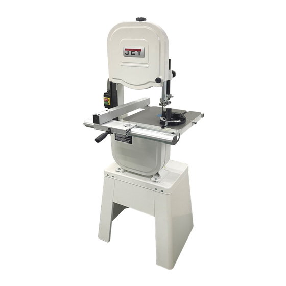
Operating Instructions and Parts Manual
14-inch Woodworking Band Saw
Model: JWBS-14DS
JPW Tool Group Hong Kong Limited
98 Granville Road, Tsimshatsui East, Kowloon, Hong Kong, PRC
www.jettools.com
Импортёр в РФ: ООО «ИТА Технолоджи»
105082, Москва, Переведеновский пер., д.17
www.jettools.ru
1
Made in Taiwan / Сделано на Тайване
M-10000237M
2023-07
Advertisement
Table of Contents

Related Manuals for Jet JWBS-14DS


Summary of Contents for Jet JWBS-14DS
- Page 1 Operating Instructions and Parts Manual 14-inch Woodworking Band Saw Model: JWBS-14DS JPW Tool Group Hong Kong Limited 98 Granville Road, Tsimshatsui East, Kowloon, Hong Kong, PRC www.jettools.com Импортёр в РФ: ООО «ИТА Технолоджи» 105082, Москва, Переведеновский пер., д.17 www.jettools.ru Made in Taiwan / Сделано на Тайване...
-
Page 2: Important Safety Instructions
5. Do not use this band saw for other than its intended use. If used for other purposes, JET disclaims any real or implied warranty and holds itself harmless from any injury that may result from that use. - Page 3 This means that if precautions are not heeded, it may result in serious injury or possibly even death. The specifications in this manual are given as general information and are not binding. JET reserves the right to effect, at any time and without prior notice, changes or alterations to parts, fittings, and...
-
Page 4: Specifications
Specifications Model number ............................. JWBS-14DS Stock number............................10000237M Motor and electricals: Motor type ............... totally enclosed fan cooled, induction, capacitor start Horsepower ............................0.75kW Phase ............................... single Voltage ..............................230V Cycle ................................50Hz Listed FLA (full load amps) ..........................6A Start capacitor .......................... -
Page 5: Shipping Contents
Shipping Contents Contents of the Carton A. Bandsaw Assembly........1 B. Stand Sides..........2 C. Stand Top ............1 D. Stand Braces………........2 E. Table w/Insert & Table Pin ......1 F. Miter Gauge Assembly.........1 G. Table Trunnion..........1 H. Table Lock Knobs 3/8"-16 ......2 I. Front Fence Rail...........1 J. -
Page 6: Unpacking And Cleanup
Assembly Read understand assembly instructions before attempting assembly! Failure to comply may cause serious injury! The required hardware for all assembly on this machine is found in the Hardware Bag for Stand Assembly and Hardware Bag for Saw Body. Unpacking and Cleanup Figure 1 1. -
Page 7: Mounting Bandsaw To Stand
1. With the aid of a second person, lift the saw body and place onto the stand top. Be sure front of bandsaw body (with JET logo) faces stand front and align the mounting holes. 2. Secure the bandsaw assembly to the stand with... - Page 8 Note: Once table is mounted to the trunnion bracket (see section below) and the blade is mounted in the saw (see section “Changing Blades”) you may choose to fine tune the blade parallel to the miter slot. Using a square positioned in the miter slot, loosen screws shown in (B, Figure 9) and lightly tap the table into position so the blade is parallel with the miter slot.
-
Page 9: Tilting The Table
Adjustments Unplug the machine from the power source before making any repairs or adjustments. Failure to comply may cause serious injury. Tilting the Table 1. Loosen front rear lock knobs (Figure 13). 2. Tilt table up to 45 degrees to the right or up to Figure 14 10 degrees to the left. -
Page 10: Adjusting Blade Tension
Adjusting Blade Tension 1. Disconnect machine from power source. 2. Make sure the blade is tensioned with the release lever in the down position (Figure16). 3. Turn blade tension knob (Fig.15) clockwise to tension blade. The blade width gauge (D, Fig.17) indicates approximate... -
Page 11: Electrical Connections
Blade guide adjustment shall never be performed Electrical Connections when the machine is running. Position the guide assembly forward/ backward so Electrical connections that the teeth keep a distance of appr. 2mm to the repairs to the electrical equipment must be guide elements. -
Page 12: Optional Accessories
Optional Accessories 708117 JRB-14 Riser Block Kit Increases depth of cut from 6" maximum to 12" maximum. Includes 6" cast block, long frame bolt, front and back blade guards, 105” blade, and mounting instructions with parts list. 10000236 JPRFA-14RU 6” High Fence with Resaw Increase the height of fence profile to 6”, include casting iron fence body and aluminum fence head... -
Page 13: Troubleshooting
(JWBS-14DX Band Saw) Troubleshooting PROBLEM POSSIBLE CAUSE SOLUTION Saw stops or will not start 1. Saw unplugged 1. Check plug connections 2. Fuse blown or circuit breaker tripped 2. Replace fuse or reset circuit breaker 3. Cord damaged 3. Replace cord Does not make accurate 1. - Page 14 JWBS-14DS Bandsaw Assembly – Exploded View...
- Page 15 JWBS-14DS Band saw Assembly – Parts List Index No. Part No. Description Size 1 ....JWBS14DS-01 ..Base ....................... 1 2 ....990180 ....... Hex Cap Screw ............M16x55......1 3 ....WF164030 ....Flat Washer .............. M16xØ 40 ....... 2 4 ....
- Page 16 43 ....RR350000 ....Retaining Ring ............R35 ........ 2 44 ....BB620203 ....Ball Bearing .............. 6202LLU ......2 45 ....AB100158 ....Lower Wheel Assembly .................. 1 46 ....TS-1550061 ....Flat Washer .............. M8xØ 30 ......1 47 ....
- Page 17 95 ....992311 ....... Spring Pin ..............Ø 3x8 ......1 96 ....100038 ....... Table Pin ......................1 97 ....100042 ....... Table Trunnion ....................2 98 ....100051 ....... Scale ......................1 99 ....100041 ....... Trunnion Clamp Shoe ..................2 100 ....
- Page 18 148 .... TS-2361061 ....Lock Washer ............M6 ......... 2 149 .... TS-1482041 ....Hex Cap Screw ............M6x20......2 150 .... TS-1503041 ....Socket Head Cap Screw .......... M6x16......2 JWBS-14DS Lower Wheel Assembly – Exploded View JWBS-14DS Lower Wheel Assembly – Parts List Index No. Part No.
- Page 19 3 ....AA198001 ....Front Rail ..............L=540 mm ..... 1 4 ....AH198001 ....Hardware Kits Package .................. 1 JWBS-14DS Hardware kits for Rip Fence – Exploded View JWBS-14DS Hardware kits for Rip Fence – Exploded View Index No Part No...
- Page 20 4 ....TS-2361061 ....Lock Washer ............M6 ......... 2 5 ....TS-1540061 ....Nut ................M8 ......... 1 6 ....TS-1550061 ....Flat Washer .............. M8x13x1.0t ....2 JWBS-14DS Open Stand Assembly – Exploded View JWBS-14DS Open Stand Assembly – Parts List Index No Part No...
-
Page 21: Electric Circuit Diagram
Electric Circuit Diagram...
Need help?
Do you have a question about the JWBS-14DS and is the answer not in the manual?
Questions and answers