
Subscribe to Our Youtube Channel
Related Manuals for GHM Delta OHM HD35 Series


Summary of Contents for GHM Delta OHM HD35 Series
- Page 1 English Operating manual Wireless data logging system HD35 series www.deltaohm.com Keep for future reference.
-
Page 2: Table Of Contents
TABLE OF CONTENTS INTRODUCTION ....................4 SYSTEM COMPONENTS ..................5 INSTALLING THE SYSTEM ..................6 NETWORK MODIFICATION .................. 11 FIXING THE HOUSING ..................12 BASE UNITS HD35AP… ..................14 .............. 14 ESCRIPTION OF VERSIONS FOR INDOOR USE HD35APR DIN ............15 ESCRIPTION OF RAIL VERSION HD35AP... - Page 3 HD35ED[L]W-MB ........... 51 ONNECTIONS IN THE OUTDOOR MODEL 8.10 HP712 HD35ED[L]WDPTC)........51 LEVEL SENSOR CONNECTION 8.11 C ....................52 ALIBRATION 8.11.1 CO .................. 52 CALIBRATION 8.11.2 D ............54 IFFERENTIAL PRESSURE CALIBRATION 8.11.3 R ............... 54 ELATIVE HUMIDITY CALIBRATION 8.11.4 P ............
-
Page 4: Introduction
1 INTRODUCTION The HD35 series wireless data logging system allows several physical quantities to be moni- tored in a large variety of application fields. Data loggers equipped with built-in sensors or external probes are available. Models with in- puts for sensors with RS485 Modbus-RTU output or standard analog sensors are also available, such as: Transmitters with 0÷20 or 4÷20 mA current output and 0÷50 mV, 0÷1 V or 0÷10 V volt- •... -
Page 5: System Components
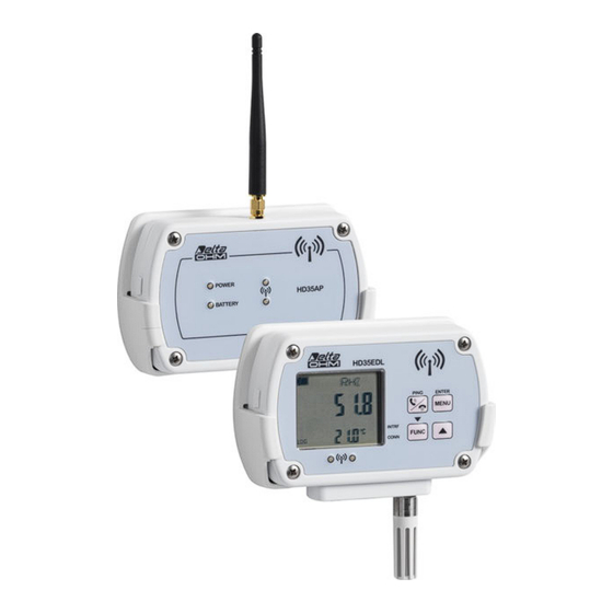
2 SYSTEM COMPONENTS The system consists of the following components: base unit • HD35AP… repeaters HD35RE… • series of data loggers HD35ED… • HD35ED-ALM remote alarm device • HD35AP… B This device acts as an interface between the network data loggers that are positioned in the measurement sites, and the PC. -
Page 6: Installing The System
3 INSTALLING THE SYSTEM Before placing the devices in the final working environment, it is recommended to perform the system function test on the bench. The bench test allows also the wireless network to be con- figured more easily, in case the supplied system is not factory-configured. To check and make the system operational, proceed as follows: 1. - Page 7 1. I HD35AP-S NSTALLING SOFTWARE Download the HD35AP-S software from the Delta OHM website. Install both HD35AP-S soft- ware and MySQL Data Base Management System (included in the package of HD35AP-S soft- ware) in your PC. Concerning the installation of MySQL, thoroughly follow the installation guide contained in the downloaded file.
- Page 8 5. C HECK THE CLOCK SETTING Select the item " Setting of date and time " of HD35AP-S software and make sure that the clock of the base unit is updated. If the clock is not updated, set it as explained in the chapter "...
- Page 9 In case of doubt of the RF stage status in the devices without LCD (for example, because LEDs seldom blink due to a long logging interval), press the connection button for 5 seconds. If the green RF LED lights up, the RF stage was not active and will be activated. If the red RF LED lights up, the RF stage was already active and will be deactivated;...
- Page 10 • In data loggers with LCD, by checking that the strength of the received signal RSSI ex- ceeds -85 dBm and that the percentage of transmission errors PER is close to zero. Use the button to display RF RSSI and PER quantities. •...
-
Page 11: Network Modification
4 NETWORK MODIFICATION One or more devices can be added or removed to/from the network at any time. DDING A DEVICE TO AN ALREADY OPERATING NETWORK To add a device to the network, connect the internal battery to the device and repeat the in- stallation procedure from step 7 concerning only the device to be added. -
Page 12: Fixing The Housing
5 FIXING THE HOUSING The installation of the indoor models is on the wall using the removable support provided or, alternatively, using the optional HD35.11K kit for fixed installation with safety lock. The outdoor models can be wall mounted using the holes on the back of the housing (accessi- ble by opening the housing) or the HD35.24W optional flange or installed on a ∅... - Page 13 Optional flange HD35.24W Fixing holes on the back Fig. 5.3: outdoor models wall mount installation modes HD35… V2.1...
-
Page 14: Base Units Hd35Ap
6 BASE UNITS HD35AP… ESCRIPTION OF VERSIONS FOR INDOOR USE 1. RF antenna for transmission in ISM band. In the HD35APW and HD35APxG models the an- tenna is on the left. In the HD35APS model, the antenna is in the center. 2. -
Page 15: Description Of Hd35Apr Din Rail Version
HD35APR DIN ESCRIPTION OF RAIL VERSION 1. RF antenna for transmission in ISM band. 2. POWER LED: in red color, it indicates the presence of an external power supply. 3. Connector for external 8…30 Vdc power supply. 4. RS485 (Modbus-RTU protocol) connector. 5. -
Page 16: Description Of Hd35Ap Xgmt Versions For Outdoor Use
HD35AP ESCRIPTION OF VERSIONS FOR OUTDOOR USE 1. RF antenna for transmission in ISM band. 2. Input for external power supply. 3. Mini-USB connector for PC connection. 4. Housing closing hooks. 5. Cellular antenna. Place the antenna at least 30 cm away from the RF antenna. HD35…... -
Page 17: Rf Leds Signals
RF LED S SIGNALS GREEN LED RED LED DESCRIPTION Initialization after a reset or battery connection. Short blink Normal operation mode. every 3 s Short blink Short blink RF alarm: at least one device exceeded the set PER every 3 s every 3 s threshold (Packet Error Rate). -
Page 18: Ethernet Or W I -F I Connection
Note: if the external power supply is not used but only the USB connection, it is recommended to connect the unit to a minimum 500 mA USB port to allow a sufficient recharging of the in- ternal battery (only for models with internal battery). ETHERNET I CONNECTION The HD35APW base unit can be connected to a PC through an Ethernet or Wi-Fi local net-... -
Page 19: Rs485 Connection
It is possible to access the base unit from any PC of the local network where the basic HD35AP-S software was installed (see the connection procedure presented in chapter " Con- nection to base unit " of the software online help). The connection to the base unit is multi-client: the unit has two TCP/IP virtual ports and ten sockets in total to be divided between the two ports. -
Page 20: Hd35Apr Connections
load characteristics of the devices to be connected. The RS485 standard requires that the total load doesn’t exceed 32 (Unit Loads). The load of a base unit HD35APR or HD35APS is equal to 1 unit load. If the total load is higher than 32 unit loads, divide the network in segments and add a signal repeater between a segment and the following. -
Page 21: Hd35Ap Gmt Power Supply
6.10 HD35AP POWER SUPPLY 0-1V 0-50mV 0-10V 0-20mA Pt100/Pt1000 External power supply Battery RT OFF RT ON 14 15 POWER BATTERY SUPPLY ATTENTION: do not reverse the battery polarity or damage will occur Fig. 6.8.1: HD35APxGMT power supply In order to power the device with a solar panel, connect the panel to the +VPanel and GND termi- nals. -
Page 22: 3G/Gsm Connection
6.11 4G/3G/GSM C ONNECTION In order to use the GSM/3G functionalities of the base units equipped with 4G/3G/GSM mod- ule, a SIM card enabled for data transmission must be inserted into the unit. The card should be requested to a carrier that has an adequate coverage of the GSM/3G network in the place where the base unit will be installed. -
Page 23: Sending Commands To The Base Unit From A Mobile Phone
tray SIM card Set down SIM release button Fig. 6.9.2: inserting the SIM card 4. Insert the SIM card into its tray so as the SIM card contacts face the outside of the tray. The tray is provided with an insertion key that prevents the possibility of inserting the SIM card improperly. - Page 24 Command Description Transmits an e-mail containing a list of all SMS commands EMAIL-HELP Activates the periodic download of measurement data via FTP FTP-ON Deactivates the periodic download of measurement data via FTP FTP-OFF FTP-PERIOD= period index Set the transmission interval via FTP, where period index: 0->15 min, 1->30 min, 2->1 hour, 3->2 hours, 4->4 hours, 5->8 hours, 6->12 hours, 7->24 hours, 8->2 days, 9->4 days, 10->1 week FTP-FORMAT= format index...
- Page 25 Command Description Deactivates the periodic upload of measurement data on the HTTP server HTTP-OFF HTTP-PERIOD= period index Set the transmission interval via HTTP, where period index: -1Real time, 015 min, 130 min, 21 hour, 32 hours, 44 hours, 58 hours, 612 hours, 724 hours, 82 days, 94 days, 101 week Activates immediate data upload on the HTTP server starting from the last HTTP-DL-START measurement transmitted...
-
Page 26: 3G/Gprs Tcp/Ip Connection
6.11.2 4G/3G/GPRS TCP/IP C ONNECTION Through 4G/3G/GPRS TCP/IP protocol, it is possible to interact with a base unit equipped with cellular module from a remote PC with an Internet connection. Power supply Fig. 6.9.3: 4G/3G/GPRS TCP/IP connection The connection can be of two types: 1) HD35APxG[MT] = Client , PC = Server HD35APxG[MT] acts as TCP client and requests the connection to the PC, the PC acts as TCP server and waits for the connection request. - Page 27 Alternatively, can be set in the server IP address or domain name and port number HD35APxG[MT] without connecting HD35APxG[MT] to the PC and without the HD35AP-S software by using the SMS commands TCP-SERVER-ADDRESS and TCP-SERVER-PORT. Connection HD35APxG[MT] = Server , PC = Client [MT] by using the SMS command TCP-LISTEN-PORT 1.
-
Page 28: Base Units Technical Specifications
6.12 B ASE UNITS TECHNICAL SPECIFICATIONS Transmission frequency 868 MHz, 902-928 MHz or 915.9-929.7 MHz according to the model Only HD35APD: 868 MHz or 902-928 MHz according to the model Antenna External whip antenna Only HD35APD: internal Transmission range In open field (it can decrease in the presence of obstacles or adverse weather conditions): 300 m (E, J)/ 180 m (U) towards data loggers with internal antenna >... - Page 29 Housing HD35APS, HD35APW, HD35APxG and HD35APR: thermoplastic (see di- mensional drawings, indoor use) HD35APxGMT: polycarbonate (270 x 170 x 110 mm, IP65 with protective cap on the USB connector) Installation HD35APS, HD35APW e HD35APxG: wall support (supplied) for removable installation or flanges (option) for fixed installation HD35APR: 35 mm DIN rail HD35APxGMT: fixing to a Ø...
-
Page 30: Hd35Re
7 HD35RE… REPEATERS HD35RE ESCRIPTION OF VERSION FOR INDOOR USE 1. RF Antenna. 2. POWER LED: red color, it indicates the presence of the external power supply; it blinks if the battery is charging. 3. BATTERY LED: green color, it indicates the internal battery charge level. When the indicator light is steady on, the battery is fully charged;... -
Page 31: Description Of Hd35Rew Version For Outdoor Use
HD35REW ESCRIPTION OF VERSION FOR OUTDOOR USE 1. RF Antenna. 2. BATTERY LED: green color, it indicates the internal battery charge level. As the battery is running low, the LED blinks with a lower and lower frequency (the blink period increases of 1 second for each 10% decrease of the battery charge). -
Page 32: Arrangement Of The Repeaters
sion. If the device doesn’t belong to a wireless network or the base unit cannot be reached, the second beep of the buzzer is not emitted and the red RF LED will blink. If the device is connected, by pressing the connection button for 5 seconds the buzzer emits a beep, the red RF LED activates for one second and the device is disconnected. -
Page 33: Repeaters Technical Specifications
EPEATERS TECHNICAL SPECIFICATIONS Transmission frequency 868 MHz, 902-928 MHz or 915.9-929.7 MHz according to the model Antenna External whip antenna Transmission range In open field (it can decrease in the presence of obstacles or adverse weather conditions): 300 m (E, J)/ 180 m (U) towards data loggers with internal antenna. >... -
Page 34: Hd35Ed
8 HD35ED… DATA LOGGERS ESCRIPTION INDOOR MODELS Models without display Models with LCD display OUTDOOR MODELS Models without display Models with LCD display ALARM LED: red color; it blinks when a measurement is in alarm condition. BATTERY LED: green color, it indicates the internal battery charge level. As the battery is running low, the LED blinks with a lower frequency (once every 5 s = battery is charged, once every 10 s = 50% battery charge, once every 15 s = battery is almost discharged). - Page 35 Connection / PING (for testing RF) button. MENU/ENTER key: allows access to the configuration menu; confirm the selected option or the set value in the menu. key: in normal operation, it scrolls the quantities measured by the data logger; it scrolls upwards the available options or increases the set value in the menu.
- Page 36 HD35EDH HD35EDWPM[B] Fixing bracket with U-bolt Air inlet Air outlet Protective cover of the terminal inputs for standard analog sensors HD35EDWPM[B] 2 M12 connectors (power supply and mini-USB) HD35EDWPM[B]-USB 1 M12 connector (power supply via mini-USB) HD35EDW1NB…TV HD35EDWH / HD35EDW-MB Power supply cable gland T/RH...
-
Page 37: Connection To Wireless Network
ONNECTION TO WIRELESS NETWORK The device can be connected and disconnected from the wireless network by pressing for 5 seconds the connection button. In the indoor models, the connection button is on the front panel. In the outdoor models, the connection button is internal and is indicated with CONNECT / DISCONNECT on the electronic board. -
Page 38: Aximum Minimum And Average Of The Measurements Only Indoor Models )
Models with graphic LCD allow the simultaneous display of 3 measurements in the secondary lines. The graphic display shows in addition the RF signal level and date & time. Logging status Connection status Battery level RF signal level 2012 04 24 16:52 Relative humidity Date... - Page 39 Press to select the option OK and confirm with ENTER. Use / keys to select a main category of the menu and confirm with ENTER. If the selected main category has a submenu, select the desired item using / and con- firm with ENTER.
- Page 40 4) Max number RF Hops: maximum number of RF hops from the data logger to the base unit (equal to the number of interposed repeaters plus 1). Read-only parame- ter if the instrument is connected to the base unit. 5) RF offline: enables or disables the RF stage of the data logger. Activation or deac- tivation of the RF stage can be performed also through the connection button.
- Page 41 For example, if Hysteresis=2%, Lower threshold=10 °C and Upper threshold=60 °C, the hysteresis is (60-10)x2/100= 1 °C: Upper threshold Hysteresis Hysteresis Lower threshold ALARM ALARM Fig. 8.5.1: hysteresis of the alarm thresholds 7) Alarm time delay (in seconds) 1) Quantity 1 alarm delay: delay for alarm activation of quantity 1.
- Page 42 10) Clock 1) Clock Configuration: date/time of data logger. Read-only parameter if the in- strument is connected to a base unit. 2) Exit: returns to the main menu. 11) Password 1) Reset password level: exits menu disabling immediately the password (the password will not remain active for some minutes like it usually happens when exit- ing a menu: you will have to re-enter the password even if you access the menu at once).
-
Page 43: The Menu In Data Loggers With Custom Lcd
8.5.2 The menu in data loggers with custom LCD To access a menu parameter proceed as follows: Press MENU, the first digit of the password will blink. Using / keys, set the first digit and confirm with ENTER, the second digit of the pass- word will blink. - Page 44 instrument is connected to a base unit. 5) RF_OFF_LINE: enables or disables the RF stage of the data logger. Select NO to activate the RF stage. Activation or deactivation of the RF stage can be done also through the connection button. 6) EXIT: returns to the main menu.
- Page 45 8) LOG_MENU (logging) 1) LOG_STAT: enables or disables the logging. 2) LOG_CYCL: choice between cyclical management (the new data overwrite the old ones when the memory is full) or non-cyclical management (logging stops when the memory is full) of the data logger memory. Select YES for the cyclical management. 3) LOG/RF_TIME: choice of logging and RF transmission interval (the two intervals coincide).
-
Page 46: M12 Connectors Pin - Out
CONNECTORS PIN The following figures show the external side of the data logger M12 connector. The arrow indi- cates the connector reference notch. Connector for rain gauges and pyranometers: - (pin 2) + (pin 1) Connector for HP3501 and HP3510… probes: pin 1 pin 2 pin 5... - Page 47 Connector for combined temperature and relative humidity probes: NTC 10KΩ Pt100 4 wires WARNING: to the data loggers that use the HP3517… combined T/RH probe must be connected the probe with the same serial number as the data logger (if purchased together). The replace- ment of the probe requires recalibration of the instrument in line with the new probe.
-
Page 48: Connections In The Indoor Model Hd35Ed[G]H
HD35ED[G]H ONNECTIONS IN THE INDOOR MODEL HD35ED[G]H has three terminal header inputs. Each input can be configured as a Pt100/Pt1000, thermocouple, 0/4…20 mA (shunt resistance inside), 0…50 mV, 0…1 V or potentiometric input. Only input 3 can be also configured as pulse counter (count of voltage-free contact switchings). Input 2 Input 3 Input 1... - Page 49 ample, if 4-20mA is selected, the data logger stores the input value in mA; if 4-20mA Mapped is selected, the data logger doesn’t store the input value in mA but the corresponding value of the physical quantity associated to the input. By selecting a Mapped-type configuration, the guided procedure for the association between the input values (in mA, mV, V, Ω...
-
Page 50: Connections In The Outdoor Model Hd35Ed[L]Wh
HD35ED[L]WH ONNECTIONS IN THE OUTDOOR MODEL HD35ED[L]WH has four terminal header inputs. Each input can be configured as a Pt100/Pt1000, thermocouple, 0/4…20 mA (shunt resistance inside), 0…50 mV, -50…50 mV, 0…1 V, 0…10 V or potentiometric input. Only input 4 can be also configured as pulse counter (count of voltage-free contact switchings). -
Page 51: Connections In The Outdoor Model Hd35Ed[L]W-Mb
HD35ED[L]W-MB ONNECTIONS IN THE OUTDOOR MODEL HD35ED[L]W-MB has: • 7…30 Vdc power supply input (terminals 1, 2). • Switched power supply output (terminals 3, 4). It has the same value as the power sup- ply input, but it is active only during the measurement acquisition phase. The out- put can be used to power the sensors. -
Page 52: Calibration
8.11 C ALIBRATION The data logger is factory-calibrated and does not normally require further interventions of the user. Anyway, a new calibration of some sensors can be performed. For a correct calibration, it is crucial to know and respect the physical phenomena which un- derlie measurements: for this reason, it is recommended to thoroughly follow the following in- structions and to perform new calibrations only if in possession of adequate technical knowledge and instruments. - Page 53 Calibration procedure: Place the instrument in an environment with known CO concentration (for ex. in clean air). Wait for at least 15 minutes for the measurement to become stable, with the instrument Access the menu with the administrator password and select the item Calibration ...
-
Page 54: Differential Pressure Calibration
The offset applied to the measurement by the auto-calibration procedure can be limited to a maximum value, so as to avoid erroneous calibrations when the measured value differs too much from the estimated background value. The auto-calibration procedure acts as follows: o If the difference between the measured value and the background value is lower than the maximum offset, an offset is applied to the measurement so that the measured value coin- cides with the background value. -
Page 55: Photometric Probe Sensitivity Setting
Bear in mind that plastic material is a bad heat conductor. Calibration should be performed at a temperature ranging within 15 and 30°C. Calibration procedure: Unscrew the probe protection grid and screw the M12×1 threaded ring. Avoid any contact of the sensitive element with your hands or other objects or liquids. If some liquid has formed inside the measuring chamber, dry it with a clean absor- bent paper towel. -
Page 56: Wbgt Index Measurement (Hd35Ed[L]Wwbgt Model )
(HD35ED[L]WWBGT 8.12 WBGT MODEL INDEX MEASUREMENT HD35ED[L]WWBGT can contemporarily detect the following quantities: Globe thermometer temperature Tg • Natural ventilation wet bulb temperature Tnw • Ambient temperature Ta • On the basis of the detected measurements, the instrument can calculate: index: WBGT index in absence of solar irradiation. - Page 57 Warning: keep the probe vertical to prevent water from leaking. Note: over time the cotton wick tends to calcify (harden): it must be replaced periodically. Preparation of the TP3204 wet bulb temperature probe: 1. Remove the sensor cap (the cap is not screwed). 2.
- Page 58 Installation on HD32.2.7.1 support: TP3507TC2 dry bulb probe TP3575TC2 or TP3576TC2 globe thermometer TP3204 wet bulb probe Screw for fixing the HD32.2.7.1 support to the tripod HD35.24W flange HD32.2.7.1 support HD35EDWWBGT data logger Installation with HD32.4.17 bracket: TP3204 wet bulb probe TP3575TC2 or TP3576TC2 globe thermometer...
- Page 59 Measurements not according to ISO 7243: The wet bulb temperature probe and the dry bulb temperature probe can be replaced (on re- quest when ordering the data logger) by the HP3517ETC2... combined temperature and relative humidity probe (Pt100 temperature sensor). The WBGT index measurement with combined temperature and relative humidity probe is not according to ISO 7243.
-
Page 60: Volatile Organic Compounds (Voc) Monitoring (Hd35Ed[G]1Nb...v Model )
(HD35ED[G]1NB…V 8.13 V (VOC) MODEL OLATILE ORGANIC COMPOUNDS MONITORING Volatile organic compounds (VOC) are polluting chemicals that evaporate easily at ambient temperature and pressure. An excessive concentration of these substances in indoor environ- ments reduces the quality of the air, causing discomfort or, in the most serious cases, altera- tions in the state of health (irritation, breathing difficulties, etc.) in the people present in the environment. -
Page 61: Data Loggers Technical Specifications
8.14 D ATA LOGGERS TECHNICAL SPECIFICATIONS Transmission frequency 868 MHz, 902-928 MHz or 915.9-929.7 MHz according to the model Antenna Internal. Only outdoor models (except HD35EDWPM…): on request, fixed or with 3 m cable external antenna. Transmission range In open field (it can decrease in the presence of obstacles or adverse weather conditions): 180 m (E, U) towards base unit HD35APD. - Page 62 Memory capacity and stored quantities Min. log (**) Model Samples number Stored quantities interval Indoor models from 42,000 to 68,000 1 s (1 ch.) HD35ED7P/xTC depending on channels nr. 5 s (3 ch.) from 42,000 to 68,000 HD35EDN/xTC depending on channels nr. HD35EDNTV 68,000 HD35ED1NTC/TV[I]...
- Page 63 (***) The minimum logging interval may be smaller if the data logger only stores some of the available quantities. (****) measurement is updated every 15 s. Measurement specifications (except HD35ED[W]H) - Instrument in line with sensor Temperature - NTC Sensor HD35ED[W]N/xTC, HD35ED[W][1][4b]NTC/TV, HD35ED1NI[2]T[C]V, HD35ED1N4r…TV, HD35EDW1NLTC, HD35EDWS…TC, HD35EDW1NB[2]TV Sensor...
- Page 64 Dry bulb temperature HD35EDWWBGT Sensor Pt100 Measuring range -40…+100 °C Resolution 0.1 °C Accuracy 1/3 DIN (TP3507TC2 probe) Stability 0.1 °C/year Wet bulb temperature HD35EDWWBGT Sensor Pt100 Measuring range +4…+80 °C Resolution 0.1 °C Accuracy Class A (TP3501TC2 and TP3204 probes) Stability 0.1 °C/year Probe reservoir capacity...
- Page 65 Atmospheric Pressure Sensor Piezoresistive Measuring range 300…1100 hPa (except HD35ED1NB[2]V and HD35EDWPMB) 700…1100 hPa (only HD35ED1NB[2]V and HD35EDWPMB) Resolution 0.1 hPa Accuracy ± 0.5 hPa (700...1100 hPa) @ 20 °C ± 1 hPa (500…1100 hPa) / ± 1.5 hPa (300…500 hPa) @ T=(0…60 °C) Only HD35ED1NB[2]V and HD35EDWPMB: ±...
- Page 66 Rainfall quantity Sensor Tipping bucket with NC or NO configurable contact Resolution Configurable 0.1 – 0.2 – 0.5 mm/tipping Solar radiation Sensor Thermopile Measuring range 0…2000 W/m Resolution 1 W/m Sensitivity Configurable in mV/(kW m Measurement characteristics not reported depend on the external sensor connected, please refer to the data sheet of the chosen external sensor.
- Page 67 Soil volumetric water content Measuring principle Capacitive Measuring range 0…60% VWC (Volumetric Water Content) Resolution 0.1% Accuracy ± 3 % between 0 and 50% VWC (standard mineral soil up to 5 mS/cm) Sensor working temperature -40…+60 °C Leaf wetness Sensor Capacitive Measuring range 0…100% of leaf area wetness...
- Page 68 Voltage input Input range 0…50 mV, -50…50 mV (only HD35EDWH), 0…1 V, 0…10 V (only HD35EDWH) Input Resistance 100 M Ω Resolution 16 bit Accuracy ± 0.01% f.s. Inputs for counting the switchings of a voltage-free contact Switching frequency 50 Hz max. Hold Time 10 ms min.
-
Page 69: Hd35Ed-Alm Remote Alarm Device
HD35ED-ALM REMOTE ALARM DEVICE ESCRIPTION ALARM LED: red color, it blinks to signal alarm conditions. BATTERY LED: green color, it indicates the internal battery charge level. As the battery is running low, the LED blinks with a lower frequency (once every 5 s = battery is charged, once every 10 s = 50% battery charge, once every 15 s = battery is almost discharged). -
Page 70: Connection To The Wireless Network
ONNECTION TO THE WIRELESS NETWORK The device can be connected and disconnected to/from the wireless network by pressing for 5 seconds the connection button on the front panel. If the device is disconnected, by pressing the connection button for 5 seconds the buzzer emits a beep and the green LED activates for one second to indicate the start of the connection pro- cedure. -
Page 71: Dimensions
10 DIMENSIONS The following figures show the dimensions of the instruments in mm. INDOOR BASE UNITS AND REPEATER: HD35APW / HD35APxG / HD35APS / HD35RE HD35APR The position of the antenna depends on model INDOOR DATA LOGGERS AND ALARM MODULE: HD35ED…TV HD35ED1NB[V] HD35ED…TC... - Page 72 HD35ED4r… Flanges for fixed installation (HD35.11K) Support for removable installation OUTDOOR DATA LOGGERS AND REPEATER: HD35REW HD35EDW…TC The numbers of connectors depends on model HD35… V2.1...
- Page 73 HD35EDW…TV HD35EDWH / HD35EDW-MB The numbers of cable glands depends on model HD35EDW1NBTV HD35EDWPM[B] This model is supplied with HD35.24C flange HD35… V2.1...
-
Page 74: Storage Of Instruments
11 STORAGE OF INSTRUMENTS Instruments storage conditions: • Temperature: -40...+70 °C. • Humidity: less than 90 %RH no condensation. • In storage, avoid places where: humidity is high; • instruments are exposed to direct sun radiation; • instruments are exposed to a high temperature source; •... -
Page 75: Probes And Accessories Ordering Codes
13 PROBES AND ACCESSORIES ORDERING CODES The devices are supplied with battery (if required by the model), HD52.03 wall mount support (only indoor models) and HD35AP-S software (downloadable from Delta OHM website). External probes, connection cables, external power supplies, other fixing accessories and the HD35AP-CFR21 advanced software (for the management of the system in accordance with the FDA 21 CFR part 11 recommendations) have to be ordered separately. - Page 76 NTC 10 KΩ temperature probe. Operating temperature: -40…+105 °C. TP35N1… Ø5 x 40 mm AISI 316 stainless steel tube. Cable length 3, 5 or 10 m stand- ard. Cable ending with free wires or 4-pole M12 connector. CABLE TERMINATION: TP35N1. Blank = free wires /C = M12 connector CABLE LENGTH:...
- Page 77 WBGT ROBES FOR MEASUREMENT Natural ventilation wet bulb probe. Pt100 sensor. Probe stem probe: Ø 14 mm, TP3501TC2 length 110 mm. 2 m cable with 4-pole M12 connector. Complete with two spare cotton wicks and 50 cc distilled water container. Natural ventilation wet bulb probe for long-lasting measurements.
- Page 78 OIL VOLUMETRIC WATER CONTENT SENSORS 2-electrode probe for measuring the soil volumetric water content. With inte- HP3510.1… grated NTC temperature sensor. 5 m (HP3510.1.5) or 10 m (HP3510.1.10) cable with M12 connector. 3-electrode probe for measuring the soil volumetric water content in restricted HP3510.2…...
- Page 79 Pair of flanges in anodized aluminum alloy for fixed installation of indoor HD35.11K models. Lock pin and padlock included. Flange in anodized aluminum alloy for fixing to the wall the outdoor mod- HD35.24W els. Not suitable for HD35EDW1NB…TV. Kit including the HD35.24W flange and a clamp for fixing the flange to a ∅ HD35.24C 40…50 mm mast.
- Page 80 Approvals Sub-GHz certifications: Models HD35….U contain transmitter module FCC ID: X7J-A10040601 IC ID: 8975A-A10040601 Model HD35….J contains TELEC certified RF module: [R] 006-000411 IEEE 802.11 (Wi-Fi) certifications: Models HD35APW.E and HD35APW.U contain IEEE 802.11b/g/n module FCC ID: XM5-SMG2N2 IC ID: 8516A-SMG2N2 Model HD35APW.J contains IEEE 802.11b/g/n module FCC ID: XM5-SMG2N2 IC ID: 8516A- SMG2N2 TELEC certified RF module: [R] 204-520077...
- Page 81 FCC and IC notices Notice: This device complies with Part 15 -15.247(a2) and 15.247(b) and 15.249 of the FCC Rules and with Industry Canada (IC) licence-exempt RSS standard(s). Operation is subject to the following two conditions: (1) this device may not cause harmful interference, and (2) this device must accept any interference received, including interference that may cause undesired operation.
- Page 82 Notes HD35… V2.1...
- Page 83 Notes HD35… V2.1...
- Page 84 GHM GROUP – Delta OHM | Delta Ohm S.r.l. a socio unico Via Marconi 5 | 35030 Caselle di Selvazzano | Padova | ITALY Phone +39 049 8977150 | Fax +39 049 635596 www.deltaohm.com | sales@deltaohm.com GARANZIA Delta OHM è tenuta a rispondere alla "garanzia di fabbrica" solo nei casi previsti dal Decreto Legislativo 6 settembre 2005, n.
Need help?
Do you have a question about the Delta OHM HD35 Series and is the answer not in the manual?
Questions and answers