
Subscribe to Our Youtube Channel
Related Manuals for GHM Delta OHM HD50CR


Summary of Contents for GHM Delta OHM HD50CR
- Page 1 English Operating manual Low pressure transmitter / data logger HD50CR Companies / Brands of GHM www.deltaohm.com Keep for future reference.
-
Page 2: Table Of Contents
TABLE OF CONTENTS INTRODUCTION ....................3 DESCRIPTION ....................... 4 INSTALLATION ..................... 5 ....................6 ONFIGURATION CONNECTION TO THE LOCAL NETWORK ..............8 HD35AP-CFR21 ................ 8 SOFTWARE OPTION ALARMS ......................10 STATISTICAL FUNCTIONS ................... 12 CALIBRATION ..................... 13 WEB SERVER ....................... 14 SETTINGS .................... -
Page 3: Introduction
1 INTRODUCTION HD50CR is a relative or differential low pressure transmitter and data logger designed for wall flush-mounting. Measuring range ±125 Pa. A silicon piezoresistive sensor with high accuracy and temperature compensation is used, which allows excellent linearity, repeatability and stability over the time. The auto-zeroing feature allows stable measurements over the time without the need to recalibrate. -
Page 4: Description
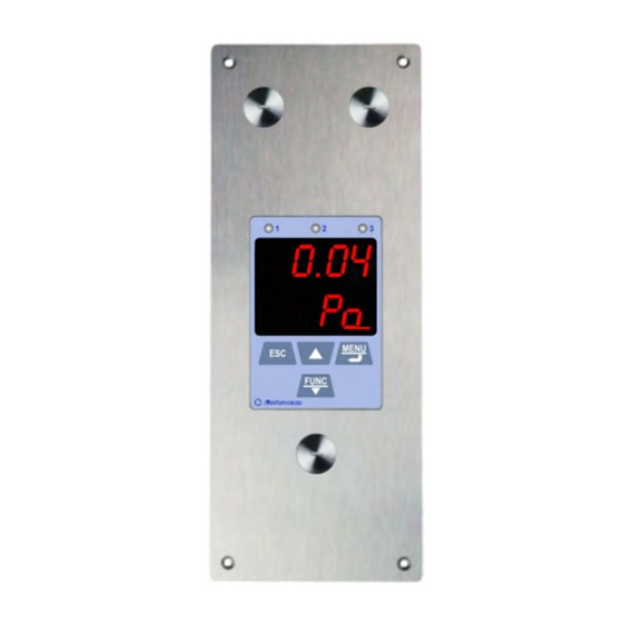
2 DESCRIPTION Pressure inputs Terminal header / ETHERNET port LEDs Inputs for pressure calibration Display Keyboard USB port with protective cap Fixing holes Input for optional T/RH probe Buttons: Scrolls the real time measurement on the display. In menu, increases the displayed value or move to the next parameter. Displays the statistical functions (MIN, MAX, AVG). -
Page 5: Installation
3 INSTALLATION Make a 196 x 70 mm cut in the wall, at least 46 mm deep, and 4 holes according to the drilling pattern shown below, then wall mount the instrument by using the 4 holes on the front panel. The connections on the upper part of the housing are as follows: ETHERNET port RS485 port... -
Page 6: Configuration
Current analog Voltage analog Power supply output connection output connection connection The three analog outputs are associated with the first three quantities of the list of se- lected quantities in the CHANNELS panel of the "web server" (see chapter 5) or, equivalently, with the quantities of index CH1, CH2 and CH3 set in the F200 menu via the front keyboard of the instrument (see chapter 7). - Page 7 • Via the Modbus protocol and the RS485 connection, for the Modbus-RTU protocol, or Ethernet connection, for the Modbus TCP/IP protocol (see chapter 10). For the use of the HD35AP-S and HDServer1 application softwares, see the corre- sponding instructions. HD50CR V1.0...
-
Page 8: Connection To The Local Network
4 CONNECTION TO THE LOCAL NETWORK The instrument can be connected to the local network via Ethernet interface (optionally Wi-Fi, on request; the two interfaces are alternatives, they cannot be used simultane- ously). To connect the instrument to an Ethernet network, connect the RJ45 connector of the instrument to a socket of the local network via a standard Ethernet cable. - Page 9 data in the database. Each user can be assigned a different password for using the software. There are also three levels of access (Administrator, Super-user and standard User); for each level, the allowed operations can be defined. The HD35AP-CFR21 option works with USB hardware key to be connected to any PC con- nected to the same local network of the PC in which the basic software is installed.
-
Page 10: Alarms
5 ALARMS For each detected quantity, two alarm thresholds can be set by the user. The alarm is generated if the measured value falls below the lower threshold or rises above the up- per threshold. Exceeding a threshold is signaled: •... - Page 11 for a configurable time. Once the set time has elapsed, the buzzer will resume sounding or not depending on whether the alarm condition is still present or not. The following example shows the silencing of the buzzer with Latch option disabled. Upper threshold Hysteresis Hysteresis...
-
Page 12: Statistical Functions
6 STATISTICAL FUNCTIONS The instrument calculates and displays the maximum (MAX), minimum (MIN) and average (AVG) value of the detected measurements. In order to display the statistical information, press FUNC/: the instrument shows the maximum value of the displayed quantity. To scroll the maximum values of the various quantities use the ... -
Page 13: Calibration
7 CALIBRATION The instrument calibrates automatically at regular intervals (default 60 minutes, the in- terval is configurable) the zero of the differential pressure, temporarily disconnecting the pressure inputs through an internal solenoid valve. Via the Fc00 menu (see chapter 7) it is possible to perform a manual calibration in one or two points. -
Page 14: Web Server
8 WEB SERVER The instrument has an integrated web server through which you can configure the in- strument and view the real time measurements from any PC, tablet or smartphone connected to the same local network of the instrument by simply using a web browser. To connect to the web server, type the IP address of the instrument in the address bar of the web browser of your device (PC, tablet, smartphone, …). -
Page 15: Settings Menu
8.1 SETTINGS MENU The SETTINGS menu allows viewing the instrument general information and configuring the Modbus parameters, the user code, the belonging group, the logging parameters, the alarms and the units of measurement. It also allows choosing the measurements to be stored in the internal memory and displayed in real time (Monitor) and in what order. - Page 16 User code Belonging group Modbus parameters Button to refresh the settings Press “Apply” to send the changes to the instrument • MEASURES panel Selection of the quantities to be displayed cyclically on the instrument display. For each quantity, a custom name can be defined. In the panel, the resolution and the unit of measurement of each quantity are also indicated.
- Page 17 Logging Measuring interval interval Active: logging is active NO Active: logging is not active Press “Apply” to send the changes to the instrument Button to erase the memory Button to refresh the settings Cyclic: cyclic overwriting of the memory NO Cyclic: logging is stopped when the memory is full If the logging interval is greater than the measuring interval, the average of the measurements acquired during the logging interval will be stored.
- Page 18 If the Buzzer Latch option is enabled, the buzzer continues to sound even after the alarm condition has ceased. The Alarm ack field allows silencing the buzzer for the set number of minutes. • UNITS panel Setting of the temperature (°C or °F) and differential pressure (mbar, bar, Pa, hPa, kPa, atm, mmHg, mmH O, inHg, inH O, kgf/cm...
- Page 19 • OUTPUTS panel Allows configuring the analog outputs. Selection 0-5 V Quantity value corresponding Button to refresh or 0-10 V to 20 mA and 5/10 V the settings Selection 0-20 mA Quantity value corresponding or 4-20 mA Press “Apply” to send the to 0/4 mA and 0 V changes to the instrument The three analog outputs are associated with the first three quantities of the list of se-...
-
Page 20: Monitor Menu
8.2 MONITOR MENU The MONITOR menu allows viewing the real time measurements, both in graphic and table form. The measurements and the corresponding date/time are updated at inter- vals equal to the logging interval. The measurements acquired by the Monitor function can be saved in a log file and exported in CSV format. - Page 21 Displays the data in the Time extension of “From” … “To” … interval the graph (X axis) Pause/Start automatic scroll X axis manual X axis manual scroll buttons scroll interval • SETUP panel Setting of the quantities and information to be displayed in the graphs. Single: all quantities on the same graph Multiple: a graph for each quantity Graphs...
-
Page 22: Connectivity Menu
8.3 CONNECTIVITY MENU The CONNECTIVITY menu allows configuring the connection to the local network and the sending of data via e-mail, FTP or to the Cloud (if the network has an Internet con- nection). It also allows setting the automatic clock synchronization and the time zone. •... - Page 23 Note: if the communication with the Cloud or the HDServer1 is used, the maximum number of “clients” with proprietary or MODBUS TCP/IP protocol is nine. Note: actually, the number of MODBUS TCP/IP connections that can be active at the same time is equal to the set number of sockets less one, because a socket is always kept free to accept new connection requests (if all the sockets are active, the socket corresponding to the oldest request is released when a new connection is accepted).
- Page 24 • EMAIL panel Setting of the e-mail account used to send data and alarms via e-mail, of the e-mail addresses of the recipients and of the e-mail data uploading modes. The data can be sent automatically at regular intervals or you can manually request the data memorized within a determined interval of time.
- Page 25 In the Files section of the EMAIL panel: o Select the Periodic Upload check box to enable the periodic sending of data via e- mail, then choose the data sending interval in the Period field. The available in- tervals are: 15 min (default), 30 min, 1 hour, 2 hours, 4 hours, 8 hours, 12 hours, 1 day, 2 days, 4 days, 1 week.
- Page 26 The Settings section of the FTP panel consists of the following fields: o FTP Server : enter the FTP server name supplied by the service provider. o FTP User : enter the user name to access the FTP service. o FTP Password : enter the password for the FTP service. o FTP Directory : enter the path of the folder in the FTP server where the files com- ing from the instrument will be transferred.
- Page 27 The URL section of the CLOUD panel consists of the following fields: o Host Address : enter the Cloud name supplied by the service provider (for ex. “www.deltaohm.cloud”). o Host Port : enter the server port number supplied by the service provider (if the standard HTTP port 80 is used, it is not necessary to indicate it).
- Page 28 The HDServer1 section of the SERVER panel consists of the following fields: o Server Address : enter the IP address of the PC in which the server function of the HDServer1 software is active. o Server Port : enter the port number of the PC in which the server function of the HDServer1 software is active.
-
Page 29: Files Menu
8.4 FILES MENU The FILES menu allows importing and viewing the files with the data sent by the in- strument via e-mail and/or FTP, or the data acquired in the past with the MONITOR function of the web server and saved in the PC, tablet or smartphone. •... -
Page 30: Menu
MENU The menu accessible via the front keyboard allows displaying the instrument infor- mation and changing operating parameters. The menu is structured in levels, with main categories and submenus. To access the menu, you need to enter the user password (configurable through the appropriate menu item) or the administrator password (supplied with the instru- ment and not editable). - Page 31 F100 submenu (DEV INFO) Instrument general information. F101: model F102: serial number F103: user code F104: group name F105: firmware version F106: firmware date F107: factory calibration date F108: user calibration date F109: type of calibration in use (factory or user) F110: external probe serial number F200 submenu (MEAS MENU) Selection and sorting of the quantities to be detected.
- Page 32 F412: lower alarm threshold enabling {On/OFF, default=On} F413: upper alarm threshold F414: upper alarm threshold enabling {On/OFF, default=On} F415: alarm hysteresis in % of the difference between the two alarm thresholds {0…100 %, default=2%} F416: delay time in signaling the alarm {max. 960 min, default=0} F417: buzzer enabling {On/OFF, default=OFF} F418: buzzer “Latch”...
- Page 33 F700 submenu (AN OUT MENU) Setting of the analog outputs. F710: analog output 1 F711: 0-20 mA / 4-20 mA selection for the current output {default=4-20 mA} F712: 0-5 V / 0-10 V selection for the voltage output {default=0-10 V} F713: value of the quantity associated with the analog output corresponding to 0/4 mA and 0 V {default=-125 Pa} F714: value of the quantity associated with the analog output corresponding to 20...
- Page 34 F805: sending interval of the of data via e-mail {Real time / 15 min / 30 min / 1 hour / 2 hours / 4 hours / 8 hours / 12 hours / 1 day / 2 days / 4 days / 1 week, default=15 min} F806: format of the data sent via e-mail {LOG=format for the database and displaying with the Monitor function of the web server, CSV=format for Excel...
- Page 35 Fb00 submenu (PSW MENU) Password settings. Fb01: exits the menu and deactivates immediately the password {YES/nO}. The password will not remain active for some minutes as it normally happens when exiting the menu: you will need to re-enter the password even if you re-access immediately the menu.
-
Page 36: Modbus
10 MODBUS The device general information can be read through the function code 0x2B/0x0E: • Manufacturer (Delta OHM) • Model • Firmware version The complete list of MODBUS registers is shown below. If you try to read a register that is not present, the instrument returns the fixed value 32767. - Page 37 Coils - Read/Write parameters Address Type Coil description Receiving mode after transmission with Modbus protocol: 0=violate protocol and go in receiving mode right after transmission 1=respect protocol and wait 3.5 characters after transmission Logging status: 0=active, 1=inactive Logging mode: 0=non cyclic, 1=cyclic Set 1 to delete the device logging memory.
- Page 38 Address Type Coil description Enabling of the buzzer “Latch” function for the quantity #4: 0= disabled, 1=enabled Enabling of the buzzer “Latch” function for the quantity #5: 0= disabled, 1=enabled Enabling of the buzzer “Latch” function for the quantity #6: 0= disabled, 1=enabled Enabling of the buzzer “Latch”...
- Page 39 Address Type Input Register description General information 10000 Year of last measurement. 10001 Month of last measurement. 10002 Day of last measurement. 10003 Hour of last measurement. 10004 Minutes of last measurement. 10005 Seconds of last measurement. 10010 Time, in seconds, elapsed since the last transmitted packet. 10011 RF signal level.
- Page 40 Address Type Holding Register description RS485 communication mode: 10035 0=8N1, 1=8N2, 2=8E1, 3=8E2, 4=8O1, 5=8O2 Password to be supplied to enable configuration change commands. The 10036 reading provides the fixed value 32768. da 10037 Device group with ASCII codification. a 10046 Acceptable values are in the set {32,…,126}.
- Page 41 Address Type Holding Register description Analog output 3 test register: the current output goes to the value, in 10093 tenths of mA, entered in the register (e.g., enter 120 for 12.0 mA). Set -1 to exit the test mode. Analog output 3 test register: the voltage output goes to the value, in 10094 tenths of V, entered in the register (e.g., enter 50 for 5.0 V).
-
Page 42: Technical Characteristics
11 TECHNICAL CHARACTERISTICS Differential Pressure Sensor Piezoresistive Measuring range ± 125 Pa Resolution 0.01 Pa Accuracy ± 0.35% typ. of measuring span (2 x full scale pressure) Zero drift Self-calibration Temperature drift ±0.5% typ. of measuring span (2 x full scale pressure) Units of measurement Pa, mmH O, mbar, inH O, mmHg, hPa... - Page 43 General characteristics Display Red electroluminescent Keyboard Yes (4 keys) Configuration Via front keys, USB or ETHERNET connection to a PC and RS485 Modbus connection Alarm Buzzer on, LED lighting and sending of e-mails Analog output 3 x 0/4…20 mA (active, max. load 500 Ω) or 3 x 0…5/10 V (min. load 10 kΩ) galvanically isolated Yes, HID type (no USB drivers) with front Mini-USB type B connector RS485...
- Page 44 Dimensions (mm): 44 - HD50CR V1.0...
-
Page 45: Instrument Storage
12 INSTRUMENT STORAGE Conditions for storage of the instrument: • Temperature: -10...+70 °C. • Humidity: below 90 %RH no condensation. • When storing, avoid places where: humidity is high; • instrument is exposed to direct solar radiation; • • instrument is exposed to high temperature source; there are strong vibrations;... -
Page 46: Ordering Codes
14 ORDERING CODES HD50CR Relative or differential low pressure transmitter / data logger designed for wall flush-mounting. Integrated Web Server. Ethernet connection (Wi-Fi on request). Measurements are stored in the internal memory and trans- mitted to an FTP address, to the Cloud and via e-mail. Three 0/4…20 mA current and 0…5/10 V voltage analog outputs. - Page 47 Approvals IEEE 802.11 (Wi-Fi) certifications: HD50CR contains IEEE 802.11b/g/n module FCC ID: XM5-SMG2N2 IC ID: 8516A- SMG2N2 TELEC certified RF module: [R] 204-520077 47 - HD50CR V1.0...
- Page 48 FCC and IC notices Notice: This device complies with Part 15 -15.247(a2) and 15.247(b) and 15.249 of the FCC Rules and with Industry Canada (IC) licence-exempt RSS standard(s). Operation is subject to the following two conditions: (1) this device may not cause harmful interference, and (2) this device must accept any interference received, including interference that may cause undesired operation.
- Page 49 OTES 49 - HD50CR V1.0...
- Page 50 OTES 50 - HD50CR V1.0...
- Page 52 G U A R A N T E E TERMS OF GUARANTEE All DELTA OHM instruments are subject to accurate testing, and are guaranteed for 24 months from the date of purchase. DELTA OHM will repair or replace free of charge the parts that, within the warranty period, shall be deemed non efficient according to its own judgement.
- Page 53 GHM GROUP – Delta OHM | Delta Ohm S.r.l. a socio unico Via Marconi 5 | 35030 Caselle di Selvazzano | Padova | ITALY Phone +39 049 8977150 | Fax +39 049 635596 www.deltaohm.com | info@deltaohm.com The quality level of our instruments is the result of the constant development of the product. This may produce some differences between the information written in this manual and the instrument you have purchased.
- Page 54 GHM GROUP – Delta OHM | Delta Ohm S.r.l. a socio unico Via Marconi 5 | 35030 Caselle di Selvazzano | Padova | ITALY Phone +39 049 8977150 | Fax +39 049 635596 www.deltaohm.com | info@deltaohm.com V1.0 27/03/2020...
Need help?
Do you have a question about the Delta OHM HD50CR and is the answer not in the manual?
Questions and answers