
Subscribe to Our Youtube Channel
Related Manuals for True FORCE SD1005


Summary of Contents for True FORCE SD1005
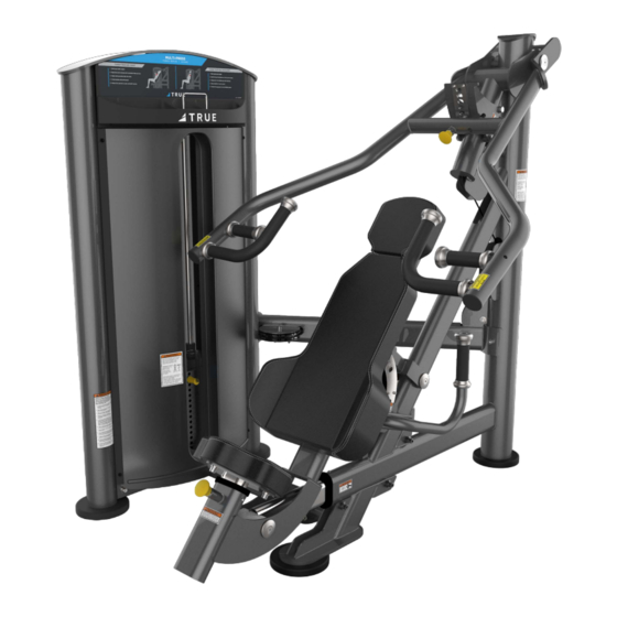
- Page 1 *Assembly Guide & Warranty Card Included MULTI-PRESS OWNER’S MANUAL Model # SD1005 Revision 071621...
- Page 2 FORCE STRENGTH OWNERS MANUAL IMPORTANT: All Products shown are prototype. Actual product delivered may vary. Product specifications, features & software are subject to change without notice. For the most up to date owner’s manual please visit www.truefitness.com. For documents in additional languages please visit www.truefitness.com/resources/document-library/ IMPORTANTE: Todos los productos mostrados son prototipos.
- Page 3 The proud manufacturing tradition of quality and the culture of innovation at TRUE have given rise to a full line of truly extraordinary treadmills, indoor cycles and elliptical cross-trainers. As a result, people all over the world are benefiting from the TRUE experience.
-
Page 4: Table Of Contents
FORCE STRENGTH OWNERS MANUAL TABLE OF CONTENTS: Chapter 1: Safety Instructions Chapter 5: Customer Service Safety Instructions Contacting Service Space Requirements Contacting Sales Working Dimensions Reporting Freight Claims or Parts Damage Warning Decals Chapter 6: Additional Information Proper Training Position Warranty Registration Chapter 2: Assembly Instructions Pre-Assembly Check List... -
Page 5: Chapter 1: Safety Instructions
*for additional information visit http://oehha.ca.gov/prop65 WARNING: Keep equipment stable on flat ground. True Fitness recommends for all strength equipment to be bolted down to the floor to avoid toppling during improper use. WARNING: Replace warning labels that may be worn, damaged or missing. - Page 6 • Never insert objects into any openings in this product. If an object should drop inside, carefully retrieve it. If the item cannot be reached, contact TRUE Customer Service. • Never place liquids of any type directly on the unit except in the accessory tray or bottle holders. Containers with lids are recommended.
-
Page 7: Space Requirements
SPACE REQUIREMENTS: TRUE’s recommendation is to leave a 40” (1.0m) safety zone on all sides of the unit. Additionally for Functional Trainers there should be enough room left for full extension of all cable in all directions. (See Fig 1) WORKING DIMENSIONS: Truefitness.com / 800.426.6570 / 636.272.7100... -
Page 8: Warning Decals
WARNING DECALS: WARNING: Replace warning labels that may be worn, damaged or missing. *To replace any worn or missing warning decals contact TRUE FITNESS by one of the following: www.truefitness.com or contact customer service at 800-883-8783. FORCE Weight Stack Labels: SWLAB175 (175 lb. Regular Weight Stack) and SWLAB255 (255 lb. Heavy Weight Stack). -
Page 9: Proper Training Position
CHAPTER 1: SAFETY INSTRUCTIONS PROPER TRAINING POSITION: Target Muscles: Chest: A. Select appropriate weight. B. Adjust back pad and press arm for desired chest exercise. C. Grasp handles and push forward. D. Perform the exercise in a slow controlled manner. Target Muscles: Shoulders: A. - Page 10 Please use the various lists in this manual to make sure that all parts have been included in your shipment. • When ordering, use part number and description from the lists. Use only True Fitness replacement part when servicing. Failure to do so will void your warranty and could result in personal injury or damage your machine.
-
Page 11: Pre-Assembly Checklist
CHAPTER 2: ASSEMBLY GUIDE PRE-ASSEMBLY CHECKLIST: Box One Contents: Item No. Description QTY. Main Frame Press Arm Pivoting Pulley Carriage Head Pad Back Pad Seat Pad Hardware Kit Truefitness.com / 800.426.6570 / 636.272.7100... - Page 12 CHAPTER 2: ASSEMBLY GUIDE PRE-ASSEMBLY CHECKLIST: Box Two Contents: Item No. Description QTY. Weight Stack Frame Cross Member Bottom Cross Member Guide Rod Left Rear Shroud Retention Plate Right Rear Shroud Retention Plate Stabilizer Foot. Weight Stack Top Plate Truefitness.com / 800.426.6570 / 636.272.7100...
-
Page 13: Item No
CHAPTER 2: ASSEMBLY GUIDE PRE-ASSEMBLY CHECKLIST: Box Three Contents: Item No. Description QTY. Accessory Tray Placard Frame Outer Shield Cap Back Shroud Front Shroud Weight Plate Cartons: Weight Plates are packaged (4) per box. The shipment should contain (4) Boxes of weight plates for a total of 16 weight plates. -
Page 14: Assembly Steps
CHAPTER 2: ASSEMBLY GUIDE UNIT ASSEMBLY STEPS: STEP 1 Frame Assembly: ITEM Description 1. Attach 2 Adjustable Foot Plates to the bottom Flat Washer M10 of the Weight Stack Frame. Spring Washer M10 Lock Nut M10 2. Secure the Bottom Cross Member, Cross Button Head Hex Socket Bolt M10*25 Member and Stability Foot to the Weight Tower Hex Bolt M10*95... -
Page 15: Main Frame
CHAPTER 2: ASSEMBLY GUIDE UNIT ASSEMBLY STEPS (continued): STEP 2 Main Frame: ITEM Description 1. Install the Main Frame as shown. Flat Washer M10 Curved Washer M10 Spring Washer M10 Lock Nut M10 Button Head Hex Socket Bolt M10X30 Main Frame Weight Stack Frame Adjustable Foot Plate Truefitness.com / 800.426.6570 / 636.272.7100... - Page 16 CHAPTER 2: ASSEMBLY GUIDE UNIT ASSEMBLY STEPS (continued): STEP 3 : 1. Lift the Pivoting Pulley Carriage into place 2. Hold the Pivoting Pulley Carriage in place throughout step 4 Weight Tower Frame Pivoting Pulley Carriage Truefitness.com / 800.426.6570 / 636.272.7100...
-
Page 17: Press Arm
CHAPTER 2: ASSEMBLY GUIDE UNIT ASSEMBLY STEPS (continued): STEP 4 Press Arm: ITEM Description 1. Install the Press Arm over Pivoting Pulley Shaft 25*206*M10 Carriage and secure as shown. End Cap 50*11*8.1 Countersunk Hex Socket Bolt M10X25 Main Bracket Truefitness.com / 800.426.6570 / 636.272.7100... - Page 18 CHAPTER 2: ASSEMBLY GUIDE UNIT ASSEMBLY STEPS (continued): STEP 5 Weight Stack Assembly: ITEM Description 1. Assemble and Install the Weight Tower as Nylon Sleeve For Guide Rod shown. Rubber Weight Bumper Flat washer M10 Spring Washer M10 Button Head Hex Socket Bolt M10*25 Guide Rods Top Plate Weight Plates...
- Page 19 CHAPTER 2: ASSEMBLY GUIDE UNIT ASSEMBLY STEPS (continued): STEP 6 Cable Routing: ITEM Description 1. Route the Cable as shown. Spacer 22*15.8*21.5 2. Tighten the cable nut on the cable bolt against Flat Washer M10 the top plate. Lock Nut M10 *Verify that the no more than 1 inch (25.4mm) Button Head Hex Socket Bolt M10X70 Bushing 10*10...
- Page 20 CHAPTER 2: ASSEMBLY GUIDE UNIT ASSEMBLY STEPS (continued): STEP 7 Seat, Back and Head Pads: ITEM Description 1. Install the Seat, Back and Head Pads as shown Flat Washer M10 below. Spring Washer M10 Button Head Hex Socket Bolt M10X30 Head Pad Back Pad Seat Pad...
- Page 21 CHAPTER 2: ASSEMBLY GUIDE UNIT ASSEMBLY STEPS (continued): STEP 8 Rear Shroud Retainer Plates ITEM Description 1. Install the Rear Shroud Retainer Plates as Countersunk Hex Socket Bolt M6*10 shown in the diagram below. Rear Shroud Retainer Plates Truefitness.com / 800.426.6570 / 636.272.7100...
- Page 22 CHAPTER 2: ASSEMBLY GUIDE UNIT ASSEMBLY STEPS (continued): STEP 9 Placard Frame: ITEM Description 1. Attach the Placard Frame to the Weight Tower Button Clip as shown. Button Head Hex Socket Bolt M5X10 Placard Frame Truefitness.com / 800.426.6570 / 636.272.7100...
- Page 23 CHAPTER 2: ASSEMBLY GUIDE UNIT ASSEMBLY STEPS (continued): STEP 10 Front Shroud: ITEM Description 1. Slide the Front Shroud into the Front Shroud Flat Washer 6.6x12x1.6 Retainer Plates. M6x20 Button Head Cap Screw 2. Secure the shroud with 4 screws and 4 washers as shown.
- Page 24 CHAPTER 2: ASSEMBLY GUIDE UNIT ASSEMBLY STEPS (continued): STEP 11 Accessory Tray & Selector pin: 1. Secure the Accessory Tray to the Placard Frame by snapping it into place. 2. Insert the Selector Pin into the weight stack and attach it to the Weight Cable Accessory Tray Selector Pin Truefitness.com / 800.426.6570 / 636.272.7100...
- Page 25 CHAPTER 2: ASSEMBLY GUIDE UNIT ASSEMBLY STEPS (continued): STEP 12 Back Shroud: ITEM Description 1. Slide the Back Shroud down into the Retainer Mushroom Head Hex Socket Bolt M6*16 Plates. Flat Washer M6 2. Secure the shroud with 4 screws and 4 washers as shown.
- Page 26 CHAPTER 2: ASSEMBLY GUIDE UNIT ASSEMBLY STEPS (continued): STEP 13 Shield Cap: ITEM Description 1. Install the Shield Cap as shown. Mushroom Head Hex Socket Bolt M6*16 Flat Washer M6 Shield Cap Truefitness.com / 800.426.6570 / 636.272.7100...
-
Page 27: Product Overview
CHAPTER 3: PRODUCT OVERVIEW PRODUCT OVERVI W: Press Arm Adjustment Pin Weight Stack Adjustment Pin Back Pad Adjustment Lever Seat Adjustment Pin Truefitness.com / 800.426.6570 / 636.272.7100... -
Page 28: Chapter 4: Care & Maintenance
The following items are critical to the safety of users and maintenance staff as well as ensuring the optimum performance of the machines. These inspections should be performed each day before the equipment is subject to use. TRUE Fitness is not responsible for performing or scheduling regular maintenance or inspections. -
Page 29: Other Scheduled Preventive Maintenance
CAUTION Do not use any acidic cleaners. Doing so will weaken the paint or powder coatings and may void the TRUE Fitness Warranty. Never pour or spray liquids on any part of the equipment. Allow the equipment to dry completely before using. -
Page 30: Cable Inspection & Maintenance
If any of these conditions are apparent, the machine should immediately be taken out of service and repaired. Be sure to use only cables supplied by TRUE Fitness. DO NOT use cables that have fittings attached with hand- crimp tools. - Page 31 CHAPTER 4: CARE & MAINTENANCE CABLE INSPECTION & MAINTENANCE (continued): Cable Tension: Ensure that the cables are adjusted to remove any slack using the threaded end fittings. These are normally located at the weight stack connection. Depending upon the machine, there may be multiple threaded fitting on multiple cables. You can determine if there is too much slack by performing the exercise.
-
Page 32: Chapter 5: Customer Service
HOURS OF OPERATION: 8:30 A.M. - 5:00 P.M. CST E-MAIL: service@truefitness.com CONTACTING SALES: Interested in TRUE Products? Please contact us with any sales or product inquires so that we may direct you to the appropriate sales representative to answer your questions. TRUE FITNESS HOME OFFICE 865 HOFF ROAD ST. -
Page 33: Reporting Freight Claims Or Parts Damage
Severe Damage: Obvious damage to external packaging / internal product. Please refuse the shipment and it will be returned to TRUE Fitness by the carrier. Contact the TRUE Fitness customer support team by calling 800.883.8783 or sales support team by calling 800.426.6570 Monday-Friday during normal business hours to notify us that the shipment has been refused. -
Page 34: Chapter 6: Additional Information
Hours of operation 8:30am - 5:00 pm CST Product. The frame is warranted for labor and freight (for parts shipped from TRUE) for one year from date of purchase. * This limited warranty on structural frame does not include paint or coatings. - Page 35 TRUE’s written approval. TRUE within 30 days of purchaser’s receipt of this Product. The serial number must be intact on the Product for this Limited FORCE STRENGTH LINE SERIAL NUMBER: Warranty to be valid.
-
Page 36: Warranty Registration
If you prefer to mail your warranty card, have the owner of the product complete the information below and return it to TRUE Fitness within 30 days from the date of equipment installation.
Need help?
Do you have a question about the FORCE SD1005 and is the answer not in the manual?
Questions and answers