
Related Manuals for True FORCE SD1001


Summary of Contents for True FORCE SD1001
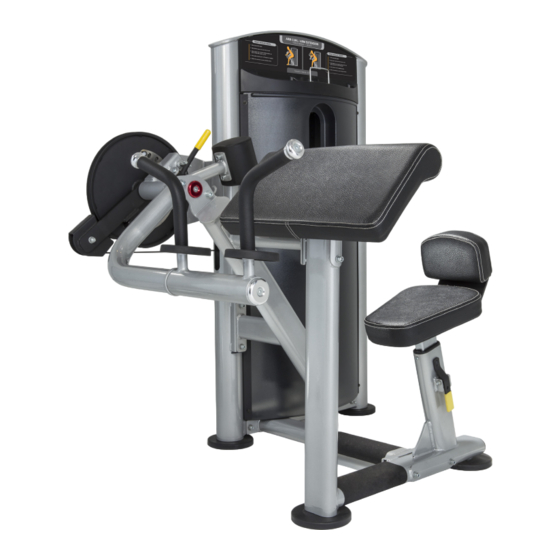
- Page 1 *Assembly Guide & Warranty Card Included BICEPS / TRICEPS OWNER’S MANUAL Model # SD1001 Revision 042617...
- Page 2 FORCE STRENGTH OWNERS MANUAL IMPORTANT: All Products shown are prototype. Actual product delivered may vary. Product specifications, features & software are subject to change without notice. For the most up to date owner’s manual please visit www.truefitness.com. For documents in additional languages please visit www.truefitness.com/resources/document-library/ IMPORTANTE: Todos los productos mostrados son prototipos.
- Page 3 The proud manufacturing tradition of quality and the culture of innovation at TRUE have given rise to a full line of xtraordinary cardio and strength equipment. As a result, people all over the world are benefiting from the TRUE experience.
-
Page 4: Table Of Contents
FORCE STRENGTH OWNERS MANUAL TABLE OF CONTENTS: Chapter 1: Safety Instructions Chapter 5: Customer Service Safety Instructions Contacting Service Space Requirements Contacting Sales Working Dimensions Reporting Freight Claims or Parts Damage Warning Decals Chapter 6: Additional Information Proper Training Position Specification Sheet Chapter 2: Assembly Instructions Warranty Registration... -
Page 5: Chapter 1: Safety Instructions
*for additional information visit http://oehha.ca.gov/prop65 WARNING: Keep equipment stable on flat ground. True Fitness recommends for all strength equipment to be bolted down to the floor to avoid toppling during improper use. WARNING: Replace warning labels that may be worn, damaged or missing. - Page 6 • Never insert objects into any openings in this product. If an object should drop inside, carefully retrieve it. If the item cannot be reached, contact TRUE Customer Service. • Never place liquids of any type directly on the unit except in the accessory tray or bottle holders. Containers with lids are recommended.
-
Page 7: Space Requirements
CHAPTER 1: SAFETY INSTRUCTIONS SPACE REQUIREMENTS: WORKING DIMENSIONS: Height Length 57” 57” 145 cm 145 cm Width Length 47.5” 57” 121 cm 145 cm Truefitness.com / 800.426.6570 / 636.272.7100... -
Page 8: Warning Decals
WARNING DECALS: WARNING: Replace warning labels that may be worn, damaged or missing. *To replace any worn or missing warning decals contact TRUE FITNESS by one of the following: www.truefitness.com or contact customer service at 800-883-8783. Truefitness.com / 800.426.6570 / 636.272.7100... -
Page 9: Proper Training Position
CHAPTER 1: SAFETY INSTRUCTIONS PROPER TRAINING POSITION: Target Muscles: Biceps A. Select appropriate weight. B. Adjust seat so upper arms rest evenly on pad and elbows align with red aluminum cap. C. Place lower back against back pad. D. Adjust rotation arm to desired starting position and grasp handles with a palms-up grip. - Page 10 Please use the various lists in this manual to make sure that all parts have been included in your shipment. • When ordering, use part number and description from the lists. Use only True Fitness replacement part when servicing. Failure to do so will void your warranty and could result in personal injury or damage your machine.
-
Page 11: Pre-Assembly Checklist
CHAPTER 2: ASSEMBLY GUIDE PRE-ASSEMBLY CHECKLIST: Box One Contents: Item No. Description QTY. Upright Assembly Cam Support Bracket Front Shroud Retainer Plates Right Shroud Retainer Plate Left Shroud Retainer Plate Stability Foot Shield Support Frame Bottom Support Frames Arm Pad Seat Pad Back Pad Guide Rods... - Page 12 CHAPTER 2: ASSEMBLY GUIDE PRE-ASSEMBLY CHECKLIST: Box Two Contents: Item No. Description QTY. Main Frame Bottom Cross Brace Seat Pad Support Hand & Arm Assembly Cam Wheel Back Pad Frame Cable Assembly Top Cross Brace Cam Pivot Bearing Arm Pad Support Directional Pulley Weight Stack Spacers Main Shaft...
- Page 13 CHAPTER 2: ASSEMBLY GUIDE PRE-ASSEMBLY CHECKLIST: Box Three Contents: Item No. Description QTY. Accessory Tray Placard Frame Outer Shroud Cap Rear Shroud Front Shroud Weight Plate Cartons: Weight Plates are packaged (4) per box. The shipment should contain (4) Boxes of weight plates for a total of 16 weight plates.
-
Page 14: Assembly Steps
CHAPTER 2: ASSEMBLY GUIDE UNIT ASSEMBLY STEPS: STEP 1 Frame Assembly: ITEM Description 1. Attach two Adjustable Foot Plates to the Flat Washer 11x20x2 bottom of the upright assembly. M10 x 100 Socket Head Cap Screw Nylon Lock Nut M10 2. - Page 15 CHAPTER 2: ASSEMBLY GUIDE UNIT ASSEMBLY STEPS (continued): STEP 2 Top & Bottom Cross Brace: ITEM Description 1. Attach two Adjustable Foot Plates to the Flat Washer 11x20x2 bottom of the Bottom Cross Brace. Socket Head Cap Screw M10x130 Socket Head Cap Screw M10x75 2.
- Page 16 CHAPTER 2: ASSEMBLY GUIDE UNIT ASSEMBLY STEPS (continued): STEP 3 Main Bracket: ITEM Description 1. Install the Cam Support Bracket as shown below. Flat Washer 13x24x2.5 Nylon Lock Nut M12 *Note: Keep both connectors securing the main frame to the upright assembly loose until the Cam Support Bracket is secured as shown below.
- Page 17 CHAPTER 2: ASSEMBLY GUIDE UNIT ASSEMBLY STEPS (continued): STEP 4 Bottom Support Frames: ITEM Description 1. Install the Bottom Support Frames as shown. Flat Washer 6.6x12x1.6 #6 Lock Washer Button Head Cap Screw M6x20 Upright Assembly Bottom Support Frame Truefitness.com / 800.426.6570 / 636.272.7100...
- Page 18 CHAPTER 2: ASSEMBLY GUIDE UNIT ASSEMBLY STEPS (continued): STEP 5 Front Shroud Retainer Plates: ITEM Description 1. Install the Front Shroud Retainer Plates as Countersunk Pan Head Screw shown below. Upright Assembly Front Shroud Retainer Plates Truefitness.com / 800.426.6570 / 636.272.7100...
- Page 19 CHAPTER 2: ASSEMBLY GUIDE UNIT ASSEMBLY STEPS (continued): STEP 6 Cam Assembly: ITEM Description 1. Using the diagram below, construct the Cam Socket Head Set Screw Assembly. 2. Tighten the Socket Set Screws on each Cam Pivot Bearing. Cam Wheel Cam Pivot Bearing Main Shaft Directional Pulley...
- Page 20 CHAPTER 2: ASSEMBLY GUIDE UNIT ASSEMBLY STEPS (continued): STEP 7 Install Cam Assembly: ITEM Description 1. Install the Cam Assembly as shown. Aluminum Cap 50x10.5x8 Flat head Cap Screw M10x25 Flat Washer 13x24x2.5 Nylon Lock Nut M12 Socket Head Cap Screw M12x35 Cam Assembly Truefitness.com / 800.426.6570 / 636.272.7100...
- Page 21 CHAPTER 2: ASSEMBLY GUIDE UNIT ASSEMBLY STEPS (continued): STEP 8 Arm Pad & Support: ITEM Description 1. Install the Arm Pad Support & Arm Pad as Flat Washer 11x20x2 Shown Socket Head Cap Screw M10x30 Socket Head Cap Screw M10x35 Arm Pad Arm Pad Support Truefitness.com / 800.426.6570 / 636.272.7100...
- Page 22 CHAPTER 2: ASSEMBLY GUIDE UNIT ASSEMBLY STEPS (continued): STEP 9 Seat Assembly: ITEM Description 1. Assemble the Seat as shown in the diagram Flat Washer 11x20x2 below. Socket Head Cap Screw M10x30 Nylon Lock Nut M10 Back Pad Seat Pad Back Pad Frame Truefitness.com / 800.426.6570 / 636.272.7100...
- Page 23 CHAPTER 2: ASSEMBLY GUIDE UNIT ASSEMBLY STEPS (continued): STEP 10 Seat Installation: 1. Remove the Seat Lock Screw. 2. Install the Seat Assembly as shown below. 3. Re-install the Seat Lock Screw. Seat Assembly Seat Lock Screw Truefitness.com / 800.426.6570 / 636.272.7100...
- Page 24 CHAPTER 2: ASSEMBLY GUIDE UNIT ASSEMBLY STEPS (continued): STEP 11 Weight Stack Assembly: ITEM Description 1. Assemble and install the guide rods and weight stack to the upright assembly as shown Weight Stack Spacer below. Rubber Weight Bumper Rubber Plugs Flat Washer 9x22x1.6 #8 Lock Washer M8x30 Socket Head Cap Screw...
- Page 25 CHAPTER 2: ASSEMBLY GUIDE UNIT ASSEMBLY STEPS (continued): STEP 12 Route Cable: ITEM Description 1. Route the cable as shown below. Cable Assy 2. Verify that no more than 1 inch (25mm) of the cable bolt thread is left exposed. CAUTION A minimum of 1/2 inch (12.7mm) of the threaded 3.
- Page 26 CHAPTER 2: ASSEMBLY GUIDE UNIT ASSEMBLY STEPS (continued): STEP 13 Shield Support Frame: ITEM Description 1. Attach the Shield Support Frame to the Flat Washer 6.5x12x1.6 upright assembly as shown below. Lock Washer #6 Button Head Cap Screw M6x20 Shield Support Frame Truefitness.com / 800.426.6570 / 636.272.7100...
- Page 27 CHAPTER 2: ASSEMBLY GUIDE UNIT ASSEMBLY STEPS (continued): STEP 14 Shroud Retainer Plates: ITEM Description 1. Install the Shroud Retainer Plates as shown. Countersunk Pan Head Screw M5x16 Upright Assembly Shroud Retainer Plates Truefitness.com / 800.426.6570 / 636.272.7100...
- Page 28 CHAPTER 2: ASSEMBLY GUIDE UNIT ASSEMBLY STEPS (continued): STEP 15 Placard Frame: ITEM Description 1. Attach the Placard Frame to the Upright Button Clip Assembly as shown below. M5x16 Countersunk Pan Head Screw Placard Frame Truefitness.com / 800.426.6570 / 636.272.7100...
- Page 29 CHAPTER 2: ASSEMBLY GUIDE UNIT ASSEMBLY STEPS (continued): STEP 16 Front Shroud: ITEM Description 1. Slide the Front Shroud into the Front Shroud Flat Washer 6.6x12x1.6 Retainer Plates. M6x20 Button Head Cap Screw 2. Secure the shroud with four screws and four washers as shown below.
- Page 30 CHAPTER 2: ASSEMBLY GUIDE UNIT ASSEMBLY STEPS (continued): STEP 17 Accessory Tray: 1. Secure the Accessory Tray to the Placard Frame by snapping it into place and then pushing down. Accessory Tray Truefitness.com / 800.426.6570 / 636.272.7100...
- Page 31 CHAPTER 2: ASSEMBLY GUIDE UNIT ASSEMBLY STEPS (continued): STEP 18 Rear Shroud: ITEM Description 1. Slide the Rear Shroud down into the Retainer Flat Washer 6.5x12x1.6 Plates. Button Head Cap Screw M6x20 2. Secure the shroud with four screws and four washers as shown below.
- Page 32 CHAPTER 2: ASSEMBLY GUIDE UNIT ASSEMBLY STEPS (continued): STEP 19 Shield Cap: ITEM Description 1. Install the Rear Shroud Cap as shown below. Flat Washer 6.5x12x1.6 Button Head Cap Screw M6x20 Truefitness.com / 800.426.6570 / 636.272.7100...
- Page 33 CHAPTER 2: ASSEMBLY GUIDE UNIT ASSEMBLY STEPS (continued): STEP 20 Selector Pin: 1. Install the Selector Pin and attach to the Weight Cable. Selector Pin Truefitness.com / 800.426.6570 / 636.272.7100...
-
Page 34: Chapter 3: Product Overview
CHAPTER 3: PRODUCT OVERVIEW PRODUCT OVERVIEW: Movement Arm Adjustment Lever Seat Adjustment Lever Truefitness.com / 800.426.6570 / 636.272.7100... -
Page 35: Chapter 4: Care & Maintenance
The following items are critical to the safety of users and maintenance staff as well as ensuring the optimum performance of the machines. These inspections should be performed each day before the equipment is subject to use. TRUE Fitness is not responsible for performing or scheduling regular maintenance or inspections. -
Page 36: Other Scheduled Preventive Maintenance
CAUTION Do not use any acidic cleaners. Doing so will weaken the paint or powder coatings and may void the TRUE Fitness Warranty. Never pour or spray liquids on any part of the equipment. Allow the equipment to dry completely before using. -
Page 37: Cable Inspection & Maintenance
If any of these conditions are apparent, the machine should immediately be taken out of service and repaired. Be sure to use only cables supplied by TRUE Fitness. DO NOT use cables that have fittings attached with hand- crimp tools. - Page 38 CHAPTER 4: CARE & MAINTENANCE CABLE INSPECTION & MAINTENANCE (continued): Cable Tension: Ensure that the cables are adjusted to remove any slack using the threaded end fittings. These are normally located at the weight stack connection. Depending upon the machine, there may be multiple threaded fitting on multiple cables. You can determine if there is too much slack by performing the exercise.
-
Page 39: Chapter 5: Customer Service
HOURS OF OPERATION: 8:30 A.M. - 5:00 P.M. CST E-MAIL: service@truefitness.com CONTACTING SALES: Interested in TRUE Products? Please contact us with any sales or product inquires so that we may direct you to the appropriate sales representative to answer your questions. TRUE FITNESS HOME OFFICE 865 HOFF ROAD ST. -
Page 40: Reporting Freight Claims Or Parts Damage
Severe Damage: Obvious damage to external packaging / internal product. Please refuse the shipment and it will be returned to TRUE Fitness by the carrier. Contact the TRUE Fitness customer support team by calling 800.883.8783 or sales support team by calling 800.426.6570 Monday-Friday during normal business hours to notify us that the shipment has been refused. - Page 41 Along with the incredible ease-of-use and intense workout experience, TRUE has also ensured the FORCE Biceps/Triceps unit addresses stability and style to guarantee long-term use and classic elegance within your facility.
- Page 42 TRUE is Impacting Fitness. TRUE has a thirty-four year history making the world’s most premium cardio equipment. Now, we are taking that same manufacturing and design quality and bringing it to you in the new FORCE strength line. All of the features you have come to associate with TRUE are found in the FORCE line…quality, durability, craftsmanship and superior aesthetics.
-
Page 43: Chapter 6: Additional Information
Hours of operation 8:30am - 5:00 pm CST Product. The frame is warranted for labor and freight (for parts shipped from TRUE) for one year from date of purchase. * This limited warranty on structural frame does not include paint or coatings. - Page 44 TRUE’s written approval. TRUE within 30 days of purchaser’s receipt of this Product. The serial number must be intact on the Product for this Limited FORCE STRENGTH LINE SERIAL NUMBER: Warranty to be valid.
-
Page 45: Warranty Registration
If you prefer to mail your warranty card, have the owner of the product complete the information below and return it to TRUE Fitness within 30 days from the date of equipment installation.
Need help?
Do you have a question about the FORCE SD1001 and is the answer not in the manual?
Questions and answers