Table of Contents
Advertisement
Quick Links
Advertisement
Table of Contents

Related Manuals for True SPL0500


Summary of Contents for True SPL0500
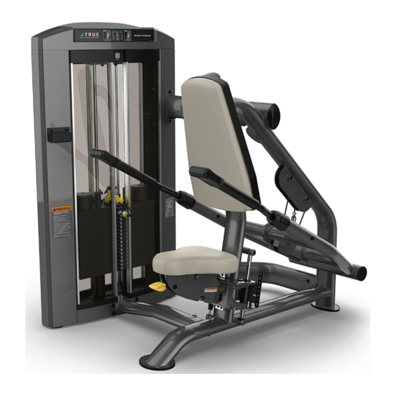
- Page 1 SPL0500 TRICEP PUSHDOWN OWNER’S MANUAL MODEL SPL0500 (MAN-SPL0500 REV00)
- Page 2 Alle hier gezeigten Produkte sind Prototypen. Das tatsächliche Produkt ausgeliefert wird, kann variieren. Produkt- Spezifi kationen, Funktionen und Software können sich ohne vorherige Ankündigung ändern. In den meisten Fällen bis zu Bedienungsanleitung Bisher besuchen und für Dokumente in weiteren Sprachen fi nden Sie unter https://truefi tness.com/ support/user-manuals/ BELANGRIJK! Alle getoonde producten zijn prototype.
- Page 3 You can count on TRUE Fitness for the best service in the industry, provided by a team focused on optimizing the life of your equipment.
- Page 4 You may receive a shipment that looks intact and discover once the box has been opened that there are hidden damages. Please notify the carrier immediately. TRUE will not be able to fi le a claim if the carrier is not notifi ed in a timely manner.
-
Page 5: Table Of Contents
WARNING AND INTENDED USE LABELS...........................12 ASSEMBLY INSTRUCTIONS PREASSEMBLY CHECKLIST...............................14 ASSEMBLY STEPS................................17 PREVENTATIVE MAINTENANCE DAILY INSPECTION AND MAINTENANCE.........................39 WEEKLY INSPECTION AND MAINTENANCE........................39 OTHER SCHEDULED PREVENTATIVE MAINTENANCE....................40 CLEANING THE EQUIPMENT..............................40 CABLE INSPECTION AND MAINTENANCE........................41 WEIGHT STACK SELECTOR PIN INSPECTION.........................44 WARRANTY INFORMATION SPL0500 COMMERCIAL LIMITED WARRANTY........................45... -
Page 6: Safety Instructions
● If the machine appears damaged or inoperable, contact a facility staff member to place an “OUT OF ORDER, DO NOT USE” sign on the machine until it is repaired. Only use TRUE supplied replacement components to service this machine. - Page 7 Frames and Lifting Arms: Inspect weekly for integrity and function. Replace any component at fi rst signs of wear. Use only TRUE supplied components. ● Replace any warning label at the fi rst sign of wear. Labels and the facility safety sign may be obtained from TRUE.
-
Page 8: General Care And Maintenance
When replacing any component, use only TRUE supplied parts. ● Be sure all hardware is tight before using the machine. Retain these instructions for future reference. If you have any questions, do not hesitate to contact your TRUE dealer or TRUE product support (service@truefi tness.com // 800.883.8783). -
Page 9: Commercial Maintenance Schedule
Clean guide rods and lubricate with a tefl on lubricant if equipped. Clean upholstery. Lubricate pivot bearings and linear bearings. Replace cables if equipped. COMPLIANCES This equipment complies with all applicable codes and regulations. For a complete list of compliances, please visit www.truefi tness.com. -
Page 10: Dimensions And Weights
190 lbs / 87 kg 250 lbs / 114 kg 310 lbs / 141 kg HEIGHT LENGTH 58” 52” 147 cm 152 cm WIDTH 48” 122 cm SHROUD OPTIONS Shroud Options Shrouds Model Description Acrylic Metal SPL0500 Tricep SPLSRDPS SPLSRDMS Pushdown... -
Page 11: Weight Stack Configurations
Number of Bumpers Top Weight** Model Description Light (L) Standard Heavy (H) Light (L) Standard Heavy (H) Generation 1 Generation 2 SPL0500 Tricep SPL-05- SPL-05- Pushdown TPL200X TPL300X SPL-ADRWT SPL-ADRWT * One box contains four 15lb / 6.8kg weight plates. -
Page 12: Warning And Intended Use Labels
WARNING AND INTENDED USE LABELS WARNING: Replace all labels that may be worn, damaged, or missing. To replace any worn or missing decals contact TRUE product support (service@truefi tness.com // 800.883.8783). TRUE FITNESS TECHNOLOGY, INC 865 HOFF RD, ST LOUIS MISSOURI 63366 USA... - Page 13 WARNING AND INTENDED USE LABELS Cable under tension from Press Arm load. Support Press Arm when changing cable. LBL-WRN-SPL023 LBL-WRN-SPL023 CUT OUT AREA LBL-ADJ-SPL033 LBL-ADJ-SPL035 Generation 1 Generation 2 LBL-ADJ-SPL010 LBL-WS-SPL310 LBL-ADJ-SPL002 LBL-QR-SPL0500 LBL-PR-SPL0500...
-
Page 14: Assembly Instructions
DO NOT use a box cutter. DO NOT slice into the packaging. VERIFY BOX CONTENTS IMPORTANT! Please verify box contents. If you have questions, or if there are any missing parts, contact product support at 800.883.8783 or service@truefi tness.com. TOOLS NEEDED FOR INCLUDED TOOLS NEEDED FOR... - Page 15 SPL-ADRWT REV03 or higher. SPL-00-GRD101X GUIDE ROD ASSEMBLY 15** SPL-00-WBR002** WEIGHT STACK BUMPER 16*** SPL-05-TPL200X*** SUBASSEMBLY, TOP WEIGHT - 1*** GENERATION 1 17*** SPL-05-TPL300X*** SUBASSEMBLY, TOP WEIGHT - 1*** GENERATION 2 18** SPLBX15** SUBASSEMBLY, SPL WEIGHT PLATES 4X15LB MAN-SPL0500 MANUAL, SPL0500...
- Page 16 BOX CONTENTS...
-
Page 17: Assembly Steps
ASSEMBLY STEPS STEP 1—ATTACH MAIN FRAME ASSEMBLY TO UPRIGHT ASSEMBLY NOTE: Supplemental assembly video available on vimeo.com: https://vimeo.com/723463817?share=copy. ITEM PART DESCRIPTION TOOL NEEDED SPL-05-MFR250X MAIN FRAME ASSEMBLY Allen Wrench SPL-05-UPR200X UPRIGHT ASSEMBLY SPL-05-CBR300 WELDMENT, CROSS BRACE SPL-05-CBR210 WELDMENT, CROSS BRACE, LOWER SPL-05-CBR250 WELDMENT, CROSS BRACE SPL-00-ECP003... - Page 18 STEP 1—ATTACH MAIN FRAME ASSEMBLY TO UPRIGHT ASSEMBLY CONTINUED b. Using an allen wrench, remove the 9 hex screws, 9 lock washers, and 1 fl at washer from the main frame assembly.
- Page 19 STEP 1—ATTACH MAIN FRAME ASSEMBLY TO UPRIGHT ASSEMBLY CONTINUED c. Using an allen wrench, loosely attach the 3 cross braces to the main frame using the 9 hex screws, 9 lock washers, and 1 fl at washer you removed previously. d.
- Page 20 STEP 1—ATTACH MAIN FRAME ASSEMBLY TO UPRIGHT ASSEMBLY CONTINUED e. Align the main frame mounting holes with the upright assembly mounting holes. NOTE: To help align parts, loosely attach all screws before fully tightening. Using an allen wrench, attach the main frame to the upright assembly using the 8 hex screws, 8 lock washers, and 4 fl...
- Page 21 STEP 2—ROUTE CABLE THROUGH UPRIGHT AND MAIN FRAME ASSEMBLIES TOOLS NEEDED ITEM PART DESCRIPTION Allen Wrench SPL-05-UPR200X UPRIGHT ASSEMBLY SPL-05-MFR250X MAIN FRAME ASSEMBLY SD0183 PULLEY 114MM Wrench SPL-05-CBL000 SUBASSEMBLY, CABLE C1258 LPSHCS, 3/8”-16 X 1-3/4” E-COAT C 766A LOCK NUT, 3/8”-16 X 17/64”, NYLON Socket Wrench C 754B WASHER, FLAT, 3/8”...
- Page 22 STEP 2—ROUTE CABLE THROUGH UPRIGHT AND MAIN FRAME ASSEMBLIES CONTINUED a. Using an allen wrench, remove and set aside the top main frame pulleys using 2 hex screws and 2 lock washers. b. Using an allen wrench and a socket wrench or open end wrench, remove and set aside the top upright pulleys using 2 hex screws, 4 fl...
- Page 23 STEP 2—ROUTE CABLE THROUGH UPRIGHT AND MAIN FRAME ASSEMBLIES CONTINUED c. Route the cable through the main frame and upright assemblies. NOTE: One person should prop up the arms to give the cable slack while another routes the cable. d. Route the cable around the top upright and main frame pulleys. e.
- Page 24 STEP 2—ROUTE CABLE THROUGH UPRIGHT AND MAIN FRAME ASSEMBLIES CONTINUED NOTE: Verify that the cable is in the groove of the lower main frame pulley.
- Page 25 STEP 3—ATTACH WEIGHT STACK TO UPRIGHT ASSEMBLY NOTE: Supplemental weight stack video available on vimeo.com: https://vimeo.com/773978716?share=copy. TOOLS NEEDED ITEM PART DESCRIPTION Allen Wrench SPL-05-UPR200X UPRIGHT ASSEMBLY SPL-00-GRB001 BRACE, GUIDE ROD SPLBX15* SUBASSEMBLY, SPL WEIGHT PLATES 4X15LB Wrench SPL-05-TPL300X SUBASSEMBLY, TOP WEIGHT - GENERATION 2 SPL-05-TPL200X SUBASSEMBLY, TOP WEIGHT - GENERATION 1 SPL-00-GRD101X...
- Page 26 STEP 3—ATTACH WEIGHT STACK TO UPRIGHT ASSEMBLY CONTINUED a. Using an allen wrench, remove and set aside the guide rod bracket from the upright assembly using 2 hex screws, 2 lock washers, and 2 fl at washers. b. Slide the 2 guide rods into place on the upright assembly.
- Page 27 STEP 3—ATTACH WEIGHT STACK TO UPRIGHT ASSEMBLY CONTINUED e. Using an allen wrench, reattach the guide rod bracket to the upright assembly using 2 hex screws, 2 lock washers, and 2 fl at washers.
- Page 28 STEP 3—ATTACH WEIGHT STACK TO UPRIGHT ASSEMBLY CONTINUED Insert the selector pin and route the cable down through the hole on the upright assembly. Using an open end wrench, attach the cable bolt to the top weight assembly. IMPORTANT! A minimum of 1/2" (12.7 mm) of the threaded portion of the cable bolt must be threaded into the top weight assembly.
- Page 29 STEP 3—ATTACH WEIGHT STACK TO UPRIGHT ASSEMBLY CONTINUED h. Insert the hex screw through the lock washer, fl at washer, and selector pin attachment point and reattach it to the Generation 1 top weight assembly using an allen wrench. Insert the hex screw through the lock washer, fl at washer, and selector pin attachment and reattach it to the Generation 2 top weight assembly using an allen wrench.
- Page 30 STEP 3—ATTACH WEIGHT STACK TO UPRIGHT ASSEMBLY CONTINUED After selecting the appropriate weight stack label, peel and remove the backing from the weight stack label. Using the selector pin retainer tube and the selector pin in the heaviest weight plate option, align the weight stack label with the plates.
- Page 31 STEP 4—ATTACH ACRYLIC SHROUDS TO UPRIGHT ASSEMBLY NOTE: Supplemental acrylic shroud video available on vimeo.com: https://vimeo.com/723539522?share=copy. NOTE: Supplemental metal shroud video available on vimeo.com: https://vimeo.com/774417897?share=copy. TOOLS NEEDED ITEM PART DESCRIPTION Allen Wrench SPL-05-UPR200X UPRIGHT ASSEMBLY SPLSRDPS* SHROUD SET SHORT ACRYLIC, SPL SPLSRDMS* SHROUD SET, SPL, SHORT METAL Flat Head Screwdriver...
- Page 32 STEP 4—ATTACH ACRYLIC SHROUDS TO UPRIGHT ASSEMBLY CONTINUED b. Assemble the acrylic front shrouds and insert them into the upright assembly using a rubber mallet. c. Using an allen wrench and a socket wrench or open end wrench, insert and tighten the 4 hex screws and 4 lock nuts into the front shrouds.
- Page 33 STEP 4—ATTACH METAL SHROUDS TO UPRIGHT ASSEMBLY a. Using an allen wrench, socket wrench or open end wrench, and a fl at head screwdriver, remove and set aside the shroud fasteners from the upright assembly using 4 hex screws, 4 lock nuts, 2 twist lock screws, and 2 lock washers.
- Page 34 STEP 4—ATTACH METAL SHROUDS TO UPRIGHT ASSEMBLY CONTINUED b. Slide the front metal shrouds onto the upright assembly. c. Using an allen wrench and a socket wrench or open end wrench, secure the front shrouds to the upright assembly using the 4 hex screws and 4 lock nuts. d.
- Page 35 STEP 5—ATTACH TOP COVER TO UPRIGHT ASSEMBLY NOTE: Supplemental top cover video available on vimeo.com: https://vimeo.com/723539522?share=copy. TOOLS NEEDED ITEM PART DESCRIPTION Allen Wrenches SPL-05-UPR200X UPRIGHT ASSEMBLY 3/32" and 5/32" SPL-00-CVR021 CAP, UPRIGHT SPL-00-CVR022 TRAY, UPRIGHT COVER SPL-00-CVR023 MAT, UPRIGHT TRAY C1239 FHCS, 8-32 X 1/2”...
- Page 36 STEP 5—ATTACH TOP COVER TO UPRIGHT ASSEMBLY CONTINUED e. Reattach the tray cover onto the top cover using the Fully press the tray mat onto the tray cover. 4 previously set aside the tray cover hex screws. top cover Verify that the tray mat is fully pressed into the tray cover.
- Page 37 STEP 6—ATTACH PHONE HOLDER TO UPRIGHT ASSEMBLY TOOL NEEDED ITEM PART DESCRIPTION #2 Phillips Screwdriver SPL-05-UPR200X UPRIGHT ASSEMBLY SPL-00-RCK001 HOLDER, PHONE C1226 PHCS, #10-32 X 1”, BLK Using a #2 Phillips screwdriver, attach the phone holder to the upright assembly using 2 screws.
- Page 38 STEP 7—ATTACH PADS TO MAIN FRAME ASSEMBLY TOOL NEEDED ITEM PART DESCRIPTION Allen Wrench SPL-05-MFR250X MAIN FRAME ASSEMBLY SPL05PDKT KIT, PAD, TRICEPS EXTENSION C1257 LPSHCS, 3/8”-16 X 1-1/4” E-COAT C 631A SHCS, 3/8”-16 X 3” BLK C 749B LOCK WASHER, 3/8”, BLK ZP C 754B WASHER, FLAT, 3/8”...
-
Page 39: Preventative Maintenance
The following items are critical to the safety of users and maintenance staff as well as ensuring the optimum performance of the machines. These inspections should be performed each day before the equipment is subject to use. TRUE is not responsible for performing or scheduling regular maintenance or inspections. -
Page 40: Other Scheduled Preventative Maintenance
Shrouds—Use a mild soap solution to clean dirt and grease marks. CAUTION: Do not use any acidic cleaners. Doing so will weaken the paint or powder coatings and may void the TRUE Warranty. Never pour or spray liquids on any part of the equipment. Allow the equipment to dry completely before using. -
Page 41: Cable Inspection And Maintenance
This means that the more often a piece of equipment is used, the greater the likelihood that cable wear will occur. This holds true for equipment made by any manufacturer and applies to urethane belts as well as wire rope cables. - Page 42 CABLE TENSION Ensure that the cables are adjusted to remove any slack using the threaded end fi ttings. These are normally located at the weight stack connection. Depending upon the machine, there may be multiple threaded fi tting on multiple cables. You can determine if there is too much slack by performing the exercise.
- Page 43 CABLE FITTING ATTACHMENTS (IF APPLICABLE) Depending upon the machine, cable end fi ttings can either be securely fi xed, rotate about a single axis, or can be free fl oating. On machines where the cable fi tting is designed to rotate about a single axis, verify that the fi tting rotates freely and that the hardware used to secure the cable pivot axle (most likely a pin or a bolt) is correctly fastened.
-
Page 44: Weight Stack Selector Pin Inspection
WEIGHT STACK SELECTOR PIN INSPECTION Verify that the weight stack selector pin is attached with the coiled lanyard to the top plate (if equipped). Verify the selector pin slides in and out of each weight plate. Place the selector pin in the top plate. Cycle the machine through the intended motion. -
Page 45: Warranty Information
HOURS OF OPERATION • This product is intended for Commercial use. If this product will not be used in this particular setting, please contact TRUE as this • Monday - Thursday 8:30am - 6:00pm (CST) warranty is void. •... - Page 46 SERIAL NUMBER: within 30 days of purchaser’s receipt of this Product. The serial The SPL0500 comes with one serial number on the base of the number must be intact on the Product for this Limited Warranty to machine. Please write down your serial number below and keep for your be valid.
- Page 47 Activate Multiple Warranties at truefi tness.com Thank you for purchasing a TRUE product. To validate the TRUE product warranty the fast and easy way, please go on- line now to truefi tness.com and register your product. The information you provide will never be distributed to any other individuals or agencies for any purpose.
- Page 48 T R U E F I T N E S S . C O M I N T E G R I T Y M A T T E R S TRUE Fitness Technology, Inc | 865 Hoff Road, St. Louis, MO 63366 © 2023 TRUE. All Rights Reserved.
Need help?
Do you have a question about the SPL0500 and is the answer not in the manual?
Questions and answers