Table of Contents
Advertisement
Quick Links
Advertisement
Table of Contents

Related Manuals for Pilz PSEN ma1.3a/b-22


Summary of Contents for Pilz PSEN ma1.3a/b-22
- Page 1 PSEN ma1.3a/b-22 PSEN sensor technology Operating Manual-21737-EN-12...
- Page 2 Preface This document is the original document. All rights to this documentation are reserved by Pilz GmbH & Co. KG. Copies may be made for the user's internal purposes. Suggestions and comments for improving this documenta- tion will be gratefully received.
-
Page 3: Table Of Contents
........................... Dimensions in mm ......................... Technical details order no. 506221, 506231 ................ Technical details order no. 506223, 506233 ................ Safety characteristic data ..................... Order reference ........................System ............................Accessories ..........................EC declaration of conformity ....................Operating Manual PSEN ma1.3a/b-22 21737-EN-12... -
Page 4: Introduction
PSEN ma1.3a/b-22 Introduction Validity of documentation This documentation is valid for the product PSEN ma1.3a/b-22. It is valid until new docu- mentation is published. This operating manual explains the function and operation, describes the installation and provides guidelines on how to connect the product. -
Page 5: Safety
If installed in other environments, measures should be taken to comply with the applicable standards and directives for the respective installation site with regard to in- terference. Operating Manual PSEN ma1.3a/b-22 21737-EN-12... -
Page 6: Safety Regulations
Disposal In safety-related applications, please comply with the mission time T in the safety-related characteristic data. When decommissioning, please comply with local regulations regarding the disposal of electronic devices (e.g. Electrical and Electronic Equipment Act). Operating Manual PSEN ma1.3a/b-22 21737-EN-12... -
Page 7: For Your Safety
LED will light. The safety switch is designed for applications in series connections. Operate the PSEN ma1.3a/b-22 in conjunction with the following components: Actuator PSEN ma1.3-08 or actuator PSEN ma1.3-12 (see... -
Page 8: Block Diagram
Block diagram Safety switch Actuator Magnet Operating distances (mm) omin Legend Assured operating distance Min. operating distance omin Assured release distance The offset-independent values for the switching distances are included in the Technical details [ 19]. Operating Manual PSEN ma1.3a/b-22 21737-EN-12... -
Page 9: Lateral And Vertical Offset
Lateral and vertical offset Actuator PSEN ma1.3-08 Legend [1] Lateral offset [2] Vertical offset [3] Sensing faces Assured operating distance S in mm Lateral offset Vertical offset The stated values are valid at a temperature of 20 °C. Operating Manual PSEN ma1.3a/b-22 21737-EN-12... - Page 10 The stated values are valid at a temperature of 20 °C. Negative vertical offset, not permitted Fig.: Safety switch and square actuator - side view Legend [1] Sensing face PSEN ma1.3-12 [2] Positive vertical offset, permitted [3] Negative vertical offset, not permitted Operating Manual PSEN ma1.3a/b-22 | 10 21737-EN-12...
-
Page 11: Wiring
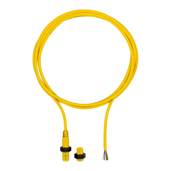
Pin assignment NOTICE The colour marking for the connection lead only applies for the cable that Pilz supplies as an accessory The safety switch is shown in an unoperated condition. Layout of the 6-core cable Brown... -
Page 12: Requirements And Connection To Evaluation Devices
PSEN ma1.3a/b-22 Requirements and connection to evaluation devices For use of PSEN ma1.3a/b-22 in accordance with DIN EN 60947-5-3 an evaluation device must be connected. Connect the PSEN ma1.3a/b-22 either with a certified Pilz evaluation device or with an evaluation device with defined properties... - Page 13 [ of PSEN ma1.3a/b-22 – Always comply with the max. switching current safety contacts of PSEN ma1.3a/b-22. Outputs at the evaluation device must only be switched on again when both reed con- tacts at the safety switch have been opened and closed (partial operation lock)
- Page 14 PSEN ma1.3a/b-22 Examples for connection to Pilz evaluation devices: PNOZ s3 PSEN ix1 PSENmag Brown White Blue Black PNOZmulti PSEN ix1 PSENmag Brown White Blue Black Auxiliary contact with LED The auxiliary contact and the LED indicate the status of the safety contacts.
-
Page 15: Installation
Prevent the safety switch and actuator being exposed to heavy shock or vibration. Make sure that the safety switch and actuator cannot be used as an end stop. Circumvention of the safety switch in a reasonably foreseeable manner must be preven- ted. Operating Manual PSEN ma1.3a/b-22 | 15 21737-EN-12... - Page 16 Note the max. torque setting (see Tech- nical details [ 19]). Installation with actuator PSEN ma1.3-08 Slide the actuator through the hole in the mounting surface with the sensing face to- wards the safety switch. Sensing face Operating Manual PSEN ma1.3a/b-22 | 16 21737-EN-12...
- Page 17 Sensing face The actuator should be secured using a set screw M3 x 6 mm DIN 319 (supplied with the device). Also note the low max. torque setting (see Technical details [ 19]). Operating Manual PSEN ma1.3a/b-22 | 17 21737-EN-12...
-
Page 18: Adjustment
Always test the function with the PSEN ix1 interface and connected evaluation device. The safety function may only be checked by qualified personnel. Dimensions in mm Safety switch 42,6 2 12,5 59,1 Actuator PSEN ma1.3-08 Actuator PSEN ma1.3-12 Operating Manual PSEN ma1.3a/b-22 | 18 21737-EN-12... -
Page 19: Technical Details Order No. 506221, 506231
Max. switching current, safety con- tacts 0,2 A 0,2 A Max. breaking capacity, safety con- tacts Max. switching current, auxiliary contacts 10 mA 10 mA Times 506221 506231 Reaction time (actuator removed) 2 ms 2 ms Operating Manual PSEN ma1.3a/b-22 | 19 21737-EN-12... - Page 20 5 m cable 5 m cable Cable LiY11Y 6 x 0,25 mm2 LiY11Y 6 x 0,25 mm2 Material Max. torque setting Safety switch 3 Nm 3 Nm Actuator 1 3 Nm 0,1 Nm Operating Manual PSEN ma1.3a/b-22 | 20 21737-EN-12...
-
Page 21: Technical Details Order No. 506223, 506233
Max. switching current, safety con- tacts 0,2 A 0,2 A Max. breaking capacity, safety con- tacts Max. switching current, auxiliary contacts 10 mA 10 mA Times 506223 506233 Reaction time (actuator removed) 2 ms 2 ms Operating Manual PSEN ma1.3a/b-22 | 21 21737-EN-12... - Page 22 10 m cable 10 m cable Cable LiY11Y 6 x 0,25 mm2 LiY11Y 6 x 0,25 mm2 Material Max. torque setting Safety switch 3 Nm 3 Nm Actuator 1 3 Nm 0,1 Nm Operating Manual PSEN ma1.3a/b-22 | 22 21737-EN-12...
-
Page 23: Safety Characteristic Data
Sensor, 2-ch, 5mA < I ≤ 60 8.500.000 Sensor, 2-ch, > 60 mA 4.000.000 NOTICE You must comply with the safety characteristic data in order to achieve the required safety level for your plant/machine. Operating Manual PSEN ma1.3a/b-22 | 23 21737-EN-12... -
Page 24: Order Reference
European Parliament and of the Council. The complete EC Declaration of Conformity is available on the Internet at www.pilz.com/downloads. Authorised representative: Norbert Fröhlich, Pilz GmbH & Co. KG, Felix-Wankel-Str. 2, 73760 Ostfildern, Germany Operating Manual PSEN ma1.3a/b-22... - Page 25 We are represented internationally. Please refer to our homepage www.pilz.com for further details or contact our headquarters. Headquarters: Pilz GmbH & Co. KG, Felix-Wankel-Straße 2, 73760 Ostfildern, Germany Telephone: +49 711 3409-0, Telefax: +49 711 3409-133, E-Mail: info@pilz.com, Internet: www.pilz.com...
Need help?
Do you have a question about the PSEN ma1.3a/b-22 and is the answer not in the manual?
Questions and answers