Table of Contents
Advertisement
Quick Links
Advertisement
Table of Contents

Subscribe to Our Youtube Channel
Related Manuals for Amada MM-L400A


Summary of Contents for Amada MM-L400A
- Page 1 LASER WELD MONITOR MM-L400A OPERATION MANUAL OM1215388 MM-L400A-E02-202307...
-
Page 2: Table Of Contents
(4) About MM-L400A ........................ 7-8 Sensitivity Check, Readjustment ................... 8-1 Specifications ........................... 9-1 10. Outline Drawing ........................10-1 (1) MM-L400A Laser Weld Monitor ..................10-1 (2) Coaxially Mounting Adapter (MM-L400A) (Optional) ............10-2 (3) External Light-Receiving Unit (Optional) ................10-3 License ............................ 11-1 Contents... -
Page 3: Special Notes
MM-L400A 1. Special Notes (1) Safety Precautions Before using the equipment, please read through the Safety Precautions carefully to ensure proper use. The precautions listed here are designed to ensure safe use and proactively prevent ■ risks and damage to the user and other people. All precautions are critical for safety. - Page 4 MM-L400A DANGER DO NOT touch anything inside the equipment. High voltage is present internally. Do not touch anything inside the equipment with the power on. NEVER ATTEMPT to disassemble, repair or modify the equipment. Failure to observe this will result in an electric shock or fire.
- Page 5 MM-L400A CAUTION DO NOT splash water. Electrical parts may cause an electric shock or short circuit if they become wet. USE proper tools (e.g., wire stripper, pressure wire connectors) for termination of connection cables. Failure to do so may damage the internal wires, leading to possibility of fire and electric shock.
-
Page 6: Handling Precautions
■ it in a tilted position may result in malfunction. For the MM-L400A, install in a location with an ambient temperature range of 5 to ■ 40ºC, ambient humidity of 85% RH or less and free from abrupt temperature changes. -
Page 7: Disposal
MM-L400A (3) Disposal The MM-L400A incorporate parts containing arsenide (As). Dust or vapor of gallium arsenide (GaAs) is harmful; handle the product with care. ・At the time of disposal, the below process is recommended: 1. The disposal work shall be subcontracted to a waste disposal specialist who is qualified for collection, transportation, and disposal of industrial waste that includes materials containing arsenic. - Page 8 MM-L400A Tearing off the seal will void the warranty. • MM-L400A Accessories The product has a Laser Aperture warning label included. Attach this label to the product or place it near to where the Fiber Unit is connected. For details, see 5 (3) “Attaching the Laser Aperture Warning label.”...
- Page 9 MM-L400A • Co-axial mounting adapter (MM-L400A) Tearing off the seal will void the warranty. • External light-receiving unit 1. Special Notes...
-
Page 10: Features
*1: Coaxial mounting is available only for selected output unit products. For details, contact us. *2: The guide light of the MM-L400A is Class 3R of JIS C 6802 “Safety standards for laser products.” 2. Features... -
Page 11: Unpacking
MM-L400A 3. Unpacking (1) Container CAUTION • At least two persons are required to remove the MM-L400A from its packing container. Dimensions Mass Remarks (including contents) 1120 35 kg Approx. (H) x (W) x (D) mm Approx. Common to the... -
Page 12: Selective Required Options
Mainly used to attenuate excessive light intensity emitted from the processing point. PC is necessary to configure the settings of the MM-L400A. A PC can be also prepared by the customers. For the PC specifications, refer to the Application Manual of the MS-Viewer. -
Page 13: Name And Function Of Each Part
Shows the status of the MM-L400A. (2) Status indicating LEDs: Indicate the current status of the MM-L400A. All of the LEDs turn on soon after startup, and as the startup process continues, each LED flashes and turns off in sequence from the right. -
Page 14: Rear
Do not connect anything to this port. (9) ANALOG INPUT Connector for input from the external device. (10) ANALOG OUT Outputs the MM-L400A detection with the analog signal. It can be observed with an oscilloscope, etc. 4. Name and Function of Each Part... -
Page 15: Optical Fiber Unit
The fiber unit connected from ch1 to ch3 of the sensor in the MM-L400A controller. (3) Fiber unit ch2: The fiber unit connected from ch5 to ch7 of the sensor in the MM-L400A controller. When the unit is configured with only a single channel, this part is hollow. -
Page 16: Connecting Equipment
(1) Typical Equipment Connection The typical equipment connection of the MM-L400A is shown below. The MM-L400A monitors the light generated from the processing point by mounting the coaxial mounting adapter (MM-L400A) coaxially with the output unit, or by mounting the external light-receiving unit. -
Page 17: Startup, Shutdown, And Power Off
Startup 1) To start up the MM-L400A, turn on the AC power switch on the rear panel. AC power switch 2) Push the controller power switch on the MM-L400A front panel. Startup operation starts, and the status indicating LEDs turn on in order. -
Page 18: Transportation And Installation
• During the operation, avoid excessive force applied to the optical fibers. • Perform install or transport operations always by two or more persons. To transport or install the MM-L400A, hold the parts at the both sides of the equipment as shown below. -
Page 19: Mounting 19" Rack
22 g) ・Equipped with a screw hole securing the front 1) Place the lower pad in the package box of the MM-L400A on a stable base such as a table, and then place the MM-L400A on the lower pad. 5. Connecting Equipment... - Page 20 3) Take out the MM-L400A from the lower pad. At this time, confirm that the bottom part is separated from the MM-L400A and remained on the lower pad. 4) Store the MM-L400A into the 19” rack by pushing from the front. At this time, pay attention not to apply forces to the optical fibers.
- Page 21 MM-L400A 5) Secure the MM-L400A from the front. The slotted hole for the MM-L400A handle is large enough to accept up to M6 screws. 6) To return to the delivered status, perform the steps 1) to 3) in the reversed order, and secure the bottom part by using the removed M4 screws (six positions).
-
Page 22: Removing/Mounting Handles
(5) Removing/Mounting Handles This section describes how to remove/mount the MM-L400A handles. CAUTION • Before starting the operation, be sure to turn off the power of MM-L400A. • Be sure to use only the specified screws. Otherwise, it may damage the product. - Page 23 MM-L400A 3) Repeat the steps 1 and 2 to remove the handle in the opposite side. 4) To secure the handles back in the places, repeat the steps 1 and 2, and use the M4 screws to co-tighten with the handle. (Recommended tightening torque: 1.27N・m)
-
Page 24: Mounting Ferrite Clamp
Be sure to mount the noise filter as specified. Mount the attached ferrite clamp at the MM-L400A side of the LAN cable with one turn. Connect the other side of the LAN cable to the personal computer. -
Page 25: Sticking Laser Aperture Label
The MM-L400A is equipped with a guide light function to confirm the measurement position. The guide light of the MM-L400A is Class 3R of JIS C 6802 “Safety of laser products”. Stick the laser aperture label near the laser aperture of the laser product as well as the product to which the fiber unit is mounted. -
Page 26: Coaxially Mounting Adapter (Mm-L400A)
L400A), the measurement light path is shifted, influencing the measurement values. Proper handling is required to use the adapter. The MM-L400A can be fixed coaxially with the output unit by mounting the coaxially mounting adapter to our output unit with CCD camera. - Page 27 MM-L400A Typical Mounting Example Output unit which the laser light is not turned The coaxially mounting adapter is fixed at the position where the laser light is turned by the output. Example) Before being mounted Camera unit Example) After being mounted (The section above dimension A is rotatable by 360 degree...
-
Page 28: Mounting External Light-Receiving Unit And Measures Against Reflected Light
In such a case, you need to take cooling measures such as water-cooled jacket. Consult us. 1) Turn on the MM-L400A power and start up the PC software MS-Viewer. Turn on the guide light of the corresponding sensor, and confirm that the guide light is irradiated from the external light-receiving unit. -
Page 29: Removing/Mounting Light Attenuation Filter Unit
1) Move the MM-L400A to a space for the operation. Replacing the optical attenuation filter unit requires a space of 120 mm or more from the top surface. - Page 30 MM-L400A 3) Hold the loosened two M4 screws, and lift them up in approximately 12 mm. As necessary, lift them up while pulling them to the front side. This can easily remove the cover plate. 4) Pull the cover plate that has been lifted to the front to remove it.
- Page 31 7) Insert the optical attenuation filter unit to the removed part, and secure it by using two M3 screws. (Recommended tightening torque: 0.69N・m) 8) Perform the steps 2 to 4 in the reversed order, return the cover of the MM-L400A back in place, and secure it by using two M4 screws. (Recommended tightening torque: 1.27N・m)
-
Page 32: Interface
MM-L400A 6. Interface (1) Inputs/Outputs Connector name Connected device Remarks Device to control the welding EXT. I/O 1.27mm pitch 50 pin Female process ANALOG INPUT Sensor, etc. D-Sub 9pin Female ANALOG OUT Oscilloscope, etc. D-Sub 25pin Female EExt. I/O (1) Not used EExt. -
Page 33: Connectors
MM-L400A (2) Connectors (3) EXT. I/O This is an interface connector (1.27 mm in pitch, 50-pin) to make connection with the external control unit. For pulse signal inputs, input should be continued for at least 1 ms. Pin No. Signal name... - Page 34 MM-L400A Pin No. Signal name Description With closed circuit input during READY, the External Trigger Input measurement starts. With closed circuit input, the mode is switched to External Control Enable the external control mode. Not used Do not connect anything.
- Page 35 MM-L400A (4) ANALOG INPUT Transmits the signals detected by the external sensors or other devices to the MM- L400A. Pin No. Signal name Description Analog IN 1 General purpose analog input terminal. (General-purpose) Voltage input: 0-10V(0-100%) Common analog ground. Analog GND Wire with the adjacent analog signals by using coaxial or twisted pair.
- Page 36 MM-L400A (3) ANALOG OUT Transmits signals from the MM-L400 to the external sensors or other devices. Pin No. Signal name Description Used to output the analog signals set by the PC Analog OUT 1 software. Voltage output: 0-10V(0-100%) Common analog GND.
- Page 37 MM-L400A (6) 24V OUT A connector for power output. 1 2 3 Pin No. Signal name Description Output terminal for 24V/1.5A Ground terminal Frame ground terminal with the same electrical potential with that of the housing. (7) LAN A connector to connect with a personal computer.
-
Page 38: Example Connections Of External Input/Output Signals
MM-L400A (3) Example Connections of External Input/Output Signals (1) When connected to an external power source *1 +24V 100mA max Never use this power ※ +24V 100mA max Inside of the laser source for anything other 装置内部 この電源は入力信号以外には、 EXT +24V than the input signals. - Page 39 MM-L400A (2) When using a contact signal *1 +24V 100mA max Never use this power ※ +24V 100mA max Inside of the laser 装置内部 この電源は入力信号以外には、 EXT +24V source for anything other 絶対に使用しないでください。 than the input signals. EXT.I/O: 1,2(24V) EXT.I/O:A1,A2(24V) Input circuit ●入力回路...
- Page 40 MM-L400A (3) When connected to an internal power source and using an open-collector signal *1 +24V 100mA max Never use this power Inside of the laser 装置内部 ※ +24V 100mA max EXT +24V source for anything other この電源は入力信号以外には、 than the input signals.
-
Page 41: Timing Chart
(4) Timing Chart Examples of timing chart are shown below for the case where the power supply of the MM-L400A is turned on, measurement by laser processing is performed and judgment is made. Each timing chart, with the equipment operation represented on the vertical axis and the... - Page 42 MM-L400A (2) To power off The following diagram shows the lapse of time in the case where the internal power of the MM-L400A is turned off. <At shutdown (by PC software)> < シャットダウン時(PCソフトで実行)> Input Input 入力 入力 Shutdown start input シャットダウン開始入力...
- Page 43 MM-L400A (3) To switch conditions An example of timing chart is shown below for the case where the condition No. is switched by using Ext. I/O. External Control Enable External control is enabled with External Control Input on External Control Enable Less than 0.5 s...
- Page 44 MM-L400A (4) From trigger input to measurement An example of timing chart is shown below for the case where the measurement is performed by the MM-L400A. Measurement does not start without Ready signal turned on READY 500 µs max. In-Measurement Less than 1 ms Less than 0.5 s...
- Page 45 An example of timing chart is shown below for the time elapsed from the measurement start using the MM-L400A to the output of a judgment result (OK or NG signals), as well as the reset of the judgment result output.
- Page 46 MM-L400A (6) Counter reset An example of timing chart is shown below for the change in counter (the values of Total and NG in the PC software MS-Viewer) as well as the time elapsed from when the counter is reset by Ext. I/O.
- Page 47 MM-L400A (7) Error Reset An example of timing chart is shown below for the time elapsed from when the Ext. I/O is used to reset errors. Group Name Timing Chart Name External Control Enable Less than 0.5 s External Control Enable 0.1 s or more...
-
Page 48: Maintenance
MM-L400A 7. Maintenance (1) Troubleshooting When an error occurs in the MM-L400A, the ERROR lamp on the display panel lights up in red. ERROR lamp Here describes the symptoms, confirmation item and measures to take. Phenomenon possibly occurring until online... - Page 49 Isn’t the trigger setting too high? Lower the set value of the trigger. Check Ext. I/O. Is the external trigger input? (See 6. Interface.) Use a filter for the MM-L400A Is the specification of the optical filter proper? with a proper specification. 7. Maintenance...
- Page 50 Operation Manual again to confirm the proper setting. *1: For the profiles of the optical filters for the MM-L400A, see (4) Options in 3.(2). When performing measurement with the same setting condition, the measurement intensity is different as shown below.
- Page 51 MM-L400A Reflective light Line Optical attenuation filter unit color Blue Without optical attenuation filter unit Gray With optical attenuation filter unit (AS1213648) Near-infrared light Line Optical attenuation filter unit color Light Without optical attenuation filter unit blue Gray With optical attenuation filter unit (AS1213648)
-
Page 52: Cleaning/Replacing Protective Glass
Model No. Protective glass KU-0037 O-ring (for protective glass) D9270 SG-26 *1 Replace the protective glass and the O-ring together. (3) Cleaning/replacement procedure 1) Turn off the power for the laser device and the power for the MM-L400A. 7. Maintenance... - Page 53 MM-L400A 2) Turn the protective glass holder at the end of the external light-receiving unit to detach it from the unit. Remove the protective glass from the protective glass holder. Protective glass Protective glass holder 3) Place several drops of ethanol on the lens cleaning paper, make a wet part contact with the protective glass, and slowly pull it from left to right.
-
Page 54: Replacing Fuse
MM-L400A (3) Replacing Fuse A fuse will be blown out if the rated voltage is exceeded (or overvoltage is applied). When this occurs, replace the fuse according to the following procedure: (1) Maintenance parts Item Model No. Fuse 02153.15MXP (2) Replacement procedure 1) Open the cover on the AC inlet. -
Page 55: About Mm-L400A
(4) About MM-L400A The MM-L400A does not guarantee the absolute value. The output intensity of the MM-L400A can be used for comparison to the relative value. It assumes that the waveform data can be always obtained with the same intensity under the determined conditions (laser output, profile, workpiece, and surface state are the same). -
Page 56: Sensitivity Check, Readjustment
The sensitivity check and readjustment can be performed at the customer site. The following environment is required for the readjustment: Provide a space for moving and working on the MM-L400A (500 mm x 700 mm or more). As necessary, the MM-L400A needs to be moved to the work space for internal adjustment. -
Page 57: Specifications
MM-L400A 9. Specifications Controller Dimensions 486(W) x 597(D) x 109(H) mm (with handle and rubber feet mounted, excluding fiber bending radius) Maximum mass Approx. 22 kg Input supply voltage Single-phase 100 to 240 V AC (-10%, +4%), 50/60 Hz Power consumption... - Page 58 MM-L400A Ambient operating 85% RH or less (without condensation) humidity Cooling method Natural air-cooled* Vibration when in use JEITA IT-1004A Class S Dust, oil mist JEITA Class S: 8 mg/m or less, 0.1 mg/m or less Temperature during -10 to 60 ºC (without condensation)
-
Page 59: Outline Drawing
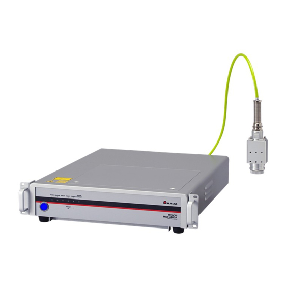
MM-L400A 10. Outline Drawing (1) MM-L400A Laser Weld Monitor Maximum mass: approx. 22 kg (Excluding the fiber unit) (Unit: mm) *1 When the bottom parts are removed, the product height is 88 mm. 10.Outline Drawing 10-1... -
Page 60: Coaxially Mounting Adapter (Mm-L400A) (Optional)
MM-L400A (2) Coaxially Mounting Adapter (MM-L400A) (Optional) Maximum mass: approx. 0.9 kg (Excluding the fiber unit and the camera unit, including the accessories to mount) (Unit: mm) Optical fiber unit Minium bending radius: R100 C-mount ring C-mount ring Output Unit *1 Use the C-mount ring (height: 4 mm) to either of the two locations. -
Page 61: External Light-Receiving Unit (Optional)
MM-L400A (3) External Light-Receiving Unit (Optional) Mass: approx. 0.4 kg (Excluding the fiber unit) (Unit: mm) Optical fiber unit Minium bending radius: R100 (incl. reversed face) (incl. reversed face) long hole (incl. reversed face) Protective glass holder 10.Outline Drawing 10-3... -
Page 62: License
MM-L400A License Apche2 / MIT License Copyright 2023 AMADA WELD TECH CO ,LTD. All Rights Reserved. Apache License Version 2.0, January 2004 http://www.apache.org/licenses/ TERMS AND CONDITIONS FOR USE, REPRODUCTION, AND DISTRIBUTION 1. Definitions. License shall mean the terms and conditions for use, reproduction, and distribution as defined by Sections 1 through 9 of this document. - Page 63 MM-L400A 2. Grant of Copyright License. Subject to the terms and conditions of this License, each Contributor hereby grants to You a perpetual, worldwide, non-exclusive, no-charge, royalty-free, irrevocable copyright license to reproduce, prepare Derivative Works of, publicly display, publicly perform, sublicense, and distribute the Work and such Derivative Works in Source or Object form.
- Page 64 MM-L400A 9. Accepting Warranty or Additional Liability. While redistributing the Work or Derivative Works thereof, You may choose to offer, and charge a fee for, acceptance of support, warranty, indemnity, or other liability obligations and/or rights consistent with this License. However, in accepting such obligations, You may act only on Your own behalf and on Your...
- Page 65 SQLite3 / Public Domain Flask / MIT License Copyright 2023 AMADA WELD TECH CO ,LTD. All Rights Reserved. Permission is hereby granted, free of charge, to any person obtaining a copy of this software and associated documentation files (the "Software"),...
- Page 66 MM-L400A The above copyright notice and this permission notice shall be included in all copies or substantial portions of the Software. THE SOFTWARE IS PROVIDED "AS IS", WITHOUT WARRANTY OF ANY KIND, EXPRESS OR IMPLIED, INCLUDING BUT NOT LIMITED TO THE WARRANTIES OF MERCHANTABILITY, FITNESS FOR A PARTICULAR PURPOSE AND NONINFRINGEMENT.
Need help?
Do you have a question about the MM-L400A and is the answer not in the manual?
Questions and answers