Table of Contents
Advertisement
Quick Links
Advertisement
Table of Contents

Related Manuals for Axminster SBW-3501H3


Summary of Contents for Axminster SBW-3501H3
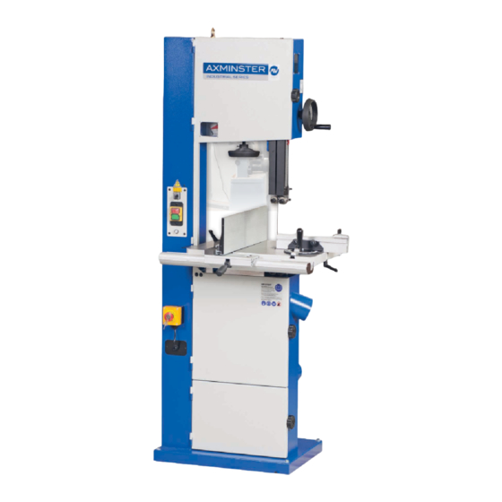
- Page 1 Code 103472 SBW-3501H3 Bandsaw AT&M: 24/05/2017 BOOK REF: 103822...
-
Page 2: Declaration Of Conformity
Index of Contents Index of Contents Declaration of Conformity What’s Included 03-04-05 General Instructions for 230V Machines Specification Main Assembly 07-08-09-10-11-12 Machine Dimensions Illustration and Parts Description 14-15-16-17-18-19 Setting Up the Saw 20-21-22-23-24-25 Operating Instructions 25-26-27 Electro-magnetic Motor Brake Switch Compact Mitre Fence Changing the Saw Blade 30-31... -
Page 3: What's Included
What’s Included Quantity Item Model Number SBW-3501H3 1 No SBW-3501H3 Industrial Bandsaw Bandsaw Blade 3,086.1mm (121.5”) long, mounted on saw but not tensioned. 1 No Cast Iron Table Fence Assembly: Bags Comprising: 1 No Front Fence Rail with Scale 1 No... - Page 4 What’s Included...
- Page 5 What’s Included...
-
Page 6: General Instructions For 230V Machines
General Instructions for 230V Machines Good Working Practices/Safety Clean the machine with a damp soapy cloth if needs be, do not The following suggestions will enable you to observe good use any solvents or cleaners as these may cause damage to any working practices, keep yourself and fellow workers safe and plastic parts or to the electrical components. -
Page 7: Specification
Specification Code 103472 Model SBW3501H3 Rating Industrial Power 1.5kW 230V 1ph Blade Speed 720m/min Blade Length 3086.1mm Blade Width Min/Max 3-19mm Max Width of Cut 342mm without fence Max Depth of Cut 356mm Max Width of Cut with Fence 315mm Noise Level 85dB Table Size... - Page 8 Main Assembly Step 1 Remove the table insert and the table shipment Fig 09-10 cap head bolt and nut and place aside, see figs 04-05. Lift the table (1), slide the blade through the table slot, rotate the table round and lower the table on to the tilt quadrant assembly, see fig 06-07.
- Page 9 Main Assembly Step 4 Locate the table alignment pin handle (13) and the large washer and nut (21). Insert the washer over the thread and screw on the nut, giving sufficient clearance between washer and nut, see fig 13. Insert the threaded handle into the slot in the cast iron table (1) and tighten so the nut clamps down in the machined recess, see fig 14.
- Page 10 Main Assembly Spanner Step 4 Locate the fence (3), M8 lift and shift handle/ M8 large washer (6) and threaded ‘T’ slot insert (7). Place the large NOTE: The fence (3) has two positions, vertical and washer over the thread of the lift and shift handle (6), introduce horizontal for cutting narrow pieces, see fig 24-25-26.
- Page 11 Main Assembly Fig 30 Fence Assembly Support Bracket The bracket helps to support the fence assembly when the fence is in position up against the saw frame to utilise the maximum width of the table (1) Locate the fence assembly support bracket (19) and the two M6 cap head screws (20).
- Page 12 Main Assembly Fig 36-37 Step 5 Locate the depth stop assembly (g), loosen the butterfly clamping knob on top of the unit. Line up the threaded ‘T’ bolt with the ‘T’ slot to the top of the aluminium fence (f) and slide on the assembly.
-
Page 13: Machine Dimensions
Machine Dimensions 740mm Code: 103472 SBW-3501H3 Industrial Bandsaw... -
Page 14: Illustration And Parts Description
Illustration and Parts Description Eye bolt lifting ring Blade tracking window Upper door locking knob Upper wheel door Upper blade guide adjusting wheel Wheel tensioning scale Upper blade guide and guard Blade tensioning wheel Fence Selector switch Upper blade guide ON/OFF buttons with emergency stop shroud Mitre fence... - Page 15 Illustration and Parts Description Key release emergency stop, press Upper blade guide height the button to stop the bandsaw and scale and pointer turn the key to release it Electro-magnetic motor brake switch NVR switch control assembly Blade tracking window Brake OFF (1), Brake ON (0), Run (2) Fence clamp assembly (4), Mitre fence (12), Fence rail with scale (2), Fence (3) Scale magnifying glass...
- Page 16 Illustration and Parts Description Wheel tension assembly Micro door switch Blade tracking window Upper saw wheel Upper wheel door Saw blade Saw table Blade tensioning scale/pointer Table insert Dust extraction outlet Drive pulley Lower saw wheel Lower wheel door Drive pulley Storage compartment Storage door...
- Page 17 Illustration and Parts Description Upper blade thrust bearing (A) Upper bearing blade guides (A) Table level angle bracket Clamping screw (B) Blade guide adjusting knob (B) with adjustable stop Blade guide fore and aft clamping screw (C) Guide assembly clamping screw (C) bolt for 90˚...
- Page 18 Illustration and Parts Description Quick release tensioning lever for Upper blade guide clamp changing the blade Tracking control knob Tracking control lock Blade tensioning wheel Tilt quadrant assembly Table levelling angle bracket with adjustable stop bolt Dust extraction outlet Motor...
- Page 19 Illustration and Parts Description Fence assembly support bracket (A) Fence lift & shift clamping handle (B) Quick release tensioning blade lever (A) Blade tensioning wheel Tracking control knob (B), Locking handle (C) Tilt quadrant clamping handle (A), Tilt quadrant rack and pinion adjusting handle (B), Tilt quadrant scale pointer (A) Tilt quadrant scale (C), Lower thrust bearing adjusting knob (D) and adjusting screw (B)
-
Page 20: Setting Up The Saw
Setting Up the Saw MAKE SURE THE SAW IS DISCONNECTED FROM THE MAINS SUPPLY! Checking the Table is Square Levelling stop bolt Step 1 Loosen the clamping handle beneath the table, see fig 39. Lower the table by turning the tilt quadrant rack and pinion adjusting handle, until it’s against the stop. - Page 21 Setting Up the Saw Hex bolts Step 2 To make sure the fence is perfectly square to the blade Magnifying scale set to ‘0’ we recommend using our unique bandsaw blade aligning tool, called the Bandsaw Buddy, see our website for details. The Bandsaw Buddy allows you to check the alignment of the bandsaw blade to the face of the fence.
- Page 22 Setting Up the Saw Fig 54-55 Fig 58-59 Tighten Loosen Fence in alignment Step 2 Apply some tension to the blade by turning the tensioning wheel clockwise, spin the top wheel by hand and Step 4 Remove the bandsaw buddy if not done so already. check that the blade remains centrally on the tyre, see fig 58-59.
- Page 23 Setting Up the Saw Fig 61-62 Fig 63 Step 7 If it doesn’t, adjust the tracking until correct. NOTE: Make very small adjustments and wait for the saw to react before you adjust again, sometimes the reaction is not instantaneous. Step 8 Once you are satisfied that the tracking is correct press the ‘RED’...
- Page 24 Setting Up the Saw Fig 69-70 Thrust bearing 2mm behind the blade Step 3 Loosen the Hex screw (C) holding one of the guide 2mm behind the gullets bearings and move to approximately 0.5mm from each side of the blade. NOTE: A sheet of A4 photocopy paper is approximately 0.5mm thick.
- Page 25 Setting Up the Saw/Operating Instructions Fig 71-72-73-74 Step 4 Re-tighten the Hex screw (F), see fig 72. When all adjustments have been made, recheck that when the blade is pressed back against the thrust bearing, both the upper and lower side guides are still behind the teeth of the saw. When all adjustments are complete, close both upper and lower doors and clear away all tools around the machine.
- Page 26 Operating Instructions 5. Check that all accessories, tools etc., that have been used cutouts (i.e. a saw cut from the edge of the material to the saw to set the machine up, are removed and set carefully aside or line) along the saw line so that you can discard the off cuts as stowed away correctly.
- Page 27 Operating Instructions Setting the Table Angle DISCONNECT THE SAW FROM THE MAINS SUPPLY! The cast iron table (1) can be tilted 0-45˚ degrees. The tilt 45˚ quadrant comprises a scale/pointer, clamping handle (A) to lock the table in set positions and a rack and pinion operating handle (B) to manoeuvre the table at set angles.
- Page 28 Electro-magnetic Motor Brake Switch The electro-magnetic brake switch is located above the Fig 84 NVR switch assembly and has three positions, see fig 83. • Position (0) engages the motor brake to prevent the bandsaw blade from moving and to isolate the bandsaw to prevent it from being started accidentally, see fig 84.
- Page 29 Compact Mitre Fence The compact mitre fence head features positive stops at 0°, The bar is 320mm long with a removable locking washer 22.5°, 30°, 45°, 60°, 67.5° and 90°, both left and right. This gives making it usable with any standard 19 x 9.5mm (3/4” x 3/8”) you 13 preset common angles in total.
-
Page 30: Changing The Saw Blade
Changing the Saw Blade Step 1 Put the table back to the level position if it has been tilted. Set the upper blade guide assembly approximately midway in the throat. Open the top and bottom wheel doors, remove the mitre fence assembly and remove the table insert, Tension released see figs 87. - Page 31 Changing the Saw Blade Fig 91 Upper blade guides Step 5 Open up all blade guides so that they are clear of the blade. Hold the blade approximately midway on either side of the loop and feed it into the table slot. When you get to the table insert cutout void, work the left side of the loop into the slot in the guard in the neck of the main saw frame.
- Page 32 Routing Maintenance Fig 99-100 DISCONNECT THE SAW FROM THE MAINS SUPPLY! Daily • Keep the machine clean. • Check the saw blade for missing teeth and cracks, see fig 97. • Spray Axcaliber Dry lubricant on the bare metal surfaces. Fig 97 Check for missing teeth and cracks in...
- Page 33 Routing Maintenance Fig 103-104-105-106 Monthly • Open the lower and upper door and check the condition of the tyres and the drive belt. Clean out all saw dust and impacted ‘crud’ from the wheels and compartment area. • Apply a little oil to the screw threads of the blade and drive belt tensioners.
- Page 34 50mm. When cutting metals reduce About Axcaliber Bandsaw Blades the speed as much as possible especially when cutting ferrous Axcaliber bandsaw blades are manufactured at Axminster using metals or cast iron. advanced CNC machining, high precision digital measuring equipment and specialised heat treatment facilities.
- Page 35 Bandsaw Blade Information Premium Bandsaw Blades •Premium blades made from M42 with 8% cobalt. • Long life with high resistance to heat, abrasion and vibration. • Variable pitch teeth for wider ranging applications. • Also used for cutting metal on horizontal bandsaws. Blades are available in three variable pitch forms 4-6tpi, 6-10tpi and 10-14tpi.
-
Page 36: Bandsaw Blades
Below is the list of top recommended accessories and machinery regular servicing (preventative maintenance) is up-sell items for the bandsaw. Please visit our website at essential to get the best from your saw. axminster.co.uk Axminster • This is the most common question that you will get from bandsaw users. - Page 37 INTRODUCTION KEY FEATURES • Bandsaw Buddy is a unique bandsaw blade aligning tool. • Designed and made in Axminster Bandsaw Buddy allows you to check the alignment of the • Unique bandsaw blade aligning tool bandsaw blade to the face of the fence. Most other checks only require the use of a combination or engineer’s square.
-
Page 38: Exploded Diagram/Parts List
Exploded Diagram/Parts List Main Saw Assembly (SBW-3501H3) - Page 39 Exploded Diagram/Parts List ITEM PART NO PARTS DESCRIPTION SIZE SR060200 HEX SOCKET BOLT M6x10 NF050800 135004 LIMPID PIECE SR060400 HEX SOCKET BOLT M6x20 SJ059400 HEX SOCKET BOTTOM M6x10 HEAR SCREW 135067 BUSHING WS050000 SPRING WASHER 995101 RING WF051210 FLAT WASHER M5x12 130485 MACHINE BODY...
- Page 40 Exploded Diagram/Parts List Main Saw Assembly (SBW-3501H3)
- Page 41 Exploded Diagram/Parts List 709412 STRAIN RELIEF PG11 SS069300 SET SCREW M6x12 IC130486 EMERGENCY SWITCH VDE0.75x2Cx1M IC130485 POWER CORD VDE1.5x3Cx3.1M CORD SJ080400 HEX SOCKET BOTTOM M8x20 HEAD SCREW 136475 PLATE WS080000 SPRING WASHER ST049200 TAPPING SCREW M4x8 AB135530 GUIDE BRACKET(ASM) WS100000 SPRING WASHER NH081300 WF102320...
- Page 42 Exploded Diagram/Parts List 14inch Fence Assembly (SBW-3501H3) ITEM PART NO DESCRIPTION SIZE 198004 FIXED LUMP 198018 FIXED BASE NH081300 198002 ADJUST BASE SF049100 PAN HEAD BOLT W/FLANGE M4x6 198003 FIXED SHAFT 198014 GUARD PIECE 198005 SHAFT 200527 MOVING PLATE 198006...
- Page 43 Exploded Diagram/Parts List Trunnion Support Bracket ASM (SBW-3501H3) NH061000 ITEM PART NO PARTS DESCRIPTION SIZE 135253 ADJUST PLATE WF081820 FLAT WASHER M8x18 SP059200 PAN HEAD BOLT W/FLANGE M5x8 NL081300 NYLON NUT SR069400 HEX SOCKET BOLT M6x16 SP049100 PAN HEAD BOLT...
- Page 44 135015 FIXED BUSHING SS050100 SET SCREW M5x5 BD101201 BUSHING BEARING DU 10x12 990306 NYLON SET SCREW M7x10 AB135095A Lower Saw Blade Adjustment ASM (SBW-3501H3) ITEM PART NO DESCRIPTION SIZE 135125 LEVER BLADE GUIDE SUPPORT SR069300 HEX SOCKET BOLT M6xl6 135124...
- Page 45 Exploded Diagram/Parts List AB135092 UpperSaw Blade Adjustment ASM (SBW-3501H3) ITEM PART NO DESCRIPTION SIZE SR069400 HEX SOCKET BOLT M6xl6 135057 UPPER GUIDE SUPPORT BLOCK 135053 ADJUST BAR 135091 UPPER BLADE GUIDE SUPPORT 135090 BIAS SHAFT RS150000 RING BB620202A BALL BEARING...
- Page 46 Exploded Diagram/Parts List Compact Mitre Fence PART DISCRIPTION HANDLE FENCE METAL WASHER 1MM PVC WASHER 2.5MM KNURLING KNOB MITRE GAUGE DIAMOND KNOB 3/8” FLIP STOP T-SHAPED SCREW RULER TAPE SQUARE NUT...
- Page 47 Exploded Diagram/Parts List ITEM PART NO DESCRIPTION SIZE 130465 LOCK KNOB M8x5 198013 HANDLE 200527 MOVING PLATE NH081300 WF082320 FLAT WASHER M8x23X2 SH060400 HEX HEAD BOLT M6x20 VS060000 SPRING WASHER VF061310 FLAT WASHER M6x013 ITEM PART NO DESCRIPTION SIZE SR069300 HEX SOCKET BOLT M6xl2 WF061620...
-
Page 48: Wiring Diagram
Wiring Diagram... - Page 49 CE Certificate...
- Page 50 Notes...
- Page 51 Notes...
- Page 52 Normal wear and tear; misuse, abuse and neglect are excluded and the machine should not have been engineering machines, Axminster Air compressors and Air Tools, and bench top grinders - no modified in any way. Please do not attempt to service the product without first contacting us; we are registration necessary just proof of purchase.
Need help?
Do you have a question about the SBW-3501H3 and is the answer not in the manual?
Questions and answers