
Related Manuals for Bomar Proline 420.350 Asx


Summary of Contents for Bomar Proline 420.350 Asx
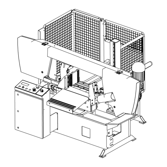
- Page 1 Series Proline Proline 420.350 Asx Operating instructions Before transporting and using the machine, please read the instructions thoroughly! Seriové číslo / Serien Nummer / Serial Number ___________________...
- Page 3 +420 – 533 426 109 62700 Brno e-mail: info@bomar.cz Czech Republic, EU www: http://www.bomar.cz We are available: Mondays to Fridays – 16 Version: 1.00 / June 2011 rev. 1 BOMAR, spol. s r.o. © – Subject to modifications and amendments. VersionNo. 00.00.00...
- Page 4 Manual version: 1.00 / June 2011 Manual rev.:...
-
Page 6: Table Of Contents
Content SAFETY NOTES ..............9 1.1. Machine determination ....................11 1.2. Protective suit and personal safety ................11 1.3. Safety notes for machine operator ................12 1.4. Safety notes for the servicing and repairs ..............13 1.5. Safety notes for the servicing and repairs on hydraulic unit ........... 13 1.6. - Page 7 DRAWING ASSEMBLIES FOR SPARE PARTS ORDER....93 7.1. Proline 420.350 Asx - 1 ....................94 7.2. Kusovník / Stückliste / Piece list – Proline 420.350 Asx - 1 ..........95 7.3. Proline 420.350 Asx - 2 ....................96 7.4. Kusovník / Stückliste / Piece list – Proline 420.350 Asx - 2 ..........97 7.5.
- Page 8 Manual version: 1.00 / June 2011 Manual rev.:...
-
Page 9: Safety Notes
Bezpečnostní pokyny Sicherheitshinweise Safety notes... - Page 10 Manual version: 1.00 / June 2011 Manual rev.:...
-
Page 11: Machine Determination
1.1. Machine determination The band saw Proline 420.350 Asx is determined for cutting and shortening of rolled bars and drawn bars and profiles from steels, stainless steels, non-ferrous metals and plastics with no angle cutting. -
Page 12: Safety Notes For Machine Operator
Wear protective shoes with non-skid soles! The unsuitable shoes may cause balance loss and following injury. Falling work pieces may cause serious injuries too. Wear protective goggles! Chips and cooling liquid may damage your eyes. Always wear ear protections! Most of the machines emit up to 80 dB and may damage your hearing. -
Page 13: Safety Notes For The Servicing And Repairs
Do not remove or do not lock the limit switches or safety equipments! Any use of the saw, accessories or machine parts other than that intended by the BOMAR, spol. s r.o. company is not permitted. The guarantee on this product will be afterward lost and BOMAR, spol. -
Page 14: Arm Covers
TOTAL STOP button is used for emergency switching – off the machine in case defect or health hazard. By pressing TOTAL STOP button is interrupted the supply of the electrical power. If any damages or fault appears, immediately press TOTAL STOP button! Release the pressing button is possible by twisting of the upper part of the button. -
Page 15: Band Saw Cover
The doors of the protective fencing are protected by limit switches. If the limit switch is open, the machine is turned off. 1.6.5. Band saw cover It covers the visible area of the saw band from left guiding cube to the frame. Never switch on the saw band driver if this cover is not mounted! 1.6.6. - Page 16 Machine label is placed on saw frame. Manual version: 1.00 / June 2011 Manual rev.:...
-
Page 17: Umístění Bezpečnostních Značek / Verteilung Der Sicherheitszeichen / Position Of Safety Symbols
1.9. Umístění bezpečnostních značek / Verteilung der Sicherheitszeichen / Position of safety symbols... -
Page 18: Machine Documentation
Dokumentace stroje Dokumentation der Maschinen Machine documentation Safety notes... - Page 19 Dokumentace stroje Dokumentation der Maschinen Machine documentation...
-
Page 20: Technická Data / Technische Daten / Technical Data
Max.jištění / Max. Vorschaltsicherung / Max. Fuse 16 A • IP 54 Krytí / Schutzart / Protection Akustický tlak / Schalldruckpegel / Acoustic pressure: • Proline 420.350 Asx = 76,3 dB Aeqv Pohon / Atrieb / Drive: • Typ / Typ / Type 112M-04 •... - Page 21 Level of acoustic pressure: Equivalent level of acoustic pressure A (noise) at operator position are L =76,3 dB. Mentioned values are Aeqv levels of emission which doesn’t have to represent safe levels. Factors which influence real level of acoustic pressure on machine operator are: working place characteristics, cut material, saw band. These factors have significantly influence on acoustic pressure.
-
Page 22: Rozměrové Schéma / Aufstellzeichnung / Installation Diagram
2.2. Rozměrové schéma / Aufstellzeichnung / Installation diagram Manual version: 1.00 / June 2011 Manual rev.:... -
Page 23: Popis / Beschreibung / Description
ameno / Säger ahmen / Saw arm Zvedací v álec / Hubz ylinder / Lifting cylinder Svěrák hla vní / Napínání pásu / Hauptsch raubstock / ägebandspannung / Main vi ce Saw band tensing Podst av ec pily / ohon pásu / Čerpadlo chla z ení... -
Page 24: Transportation And Stocking
2.4. Transportation and stocking 2.4.1. Conditions for transportation and stocking Keep recommendations for the manufacturers for transportation and stocking! If the recommendations are not kept, damage can occur to the machine. • Don’t use a forklift truck for handling the machine, if you do not have license for •... -
Page 25: Transportní Schéma / Transport Schema / Transport Scheme
2.4.4. Transportní schéma / Transport schema / Transport scheme... -
Page 26: Activation
Minimal requirement: machine weight – Proline 420.350 Asx – 1200 kg + weight of accessories + maximum weight of material • The machine must be levelled at the horizontal position. All feet of the machine must touch with the floor after levelling •... -
Page 27: Machine Disposal After Lifetime
• For machine levelling, take care that there is sufficient available space for operation, repair work, servicing of the machine and handling the material.. • The machine including appended parts and accessories must be visible from the place of operation. 2.6.2. - Page 28 Oil type Kinematic viscosity v in mm²/s in relationship to the fluid temperatur Freezing point 0°C 20°C 40°C 60°C 80°C °C OH-HM 32 OH-HM 46 OH-HM 68 OH-HV 32 OH-HV 46 Manual version: 1.00 / June 2011 Manual rev.:...
-
Page 29: Kotevní Plan / Verankerungsplan / Grounding Plan
2.6.5. Kotevní plan / Verankerungsplan / Grounding plan Kotvící materiál / Verankerungsm aterial / Grouding material • 4× Hmoždina / Dübel / Plug – ø12 mm • Vrtáno do hloub ky / In die Tiefe gebohrt / Drilled to – 95 mm •... -
Page 30: Electrical Connection
2.7. Electrical connection Attention! Only a qualified professional must carry out the servicing and repairs of the electric equipment! Take special care during work with electrical equipment. High voltage shock can have fatal consequences! Always keep notes about work safety. Electrical parameters of the machine: •... -
Page 31: Check Machine Connection Into Electrical Network
The important factor for selection of the tooth system is length of the cutting canal with respect to the size of the product BOMAR recommended Variable tooth system for band saw. Attention! When you connect the machine to the electrical network... -
Page 32: Saw Band Running-In
Constant tooth system – the saw band has parallel tooth pitch all over length. This way is suitable for cutting of solid material. Variable tooth system – tooth pitch is variable. Variable tooth system is used for profiled materials and bundle cutting. Variable tooth pitch lowers vibration of the saw band, increases service life of the saw band and quality of the cutting area. -
Page 33: Tables For Teeth Selection
2.10.4. Tables for teeth selection SHAPED MATERIAL (D , S = mm) Note: Table shows tooth system selection for cutting one piece of the profile. For cutting of more pieces of the profiles (bundle), you must think of the size of the wall as double size of the wall of one profile (that means, size „S“ equates to 2×S). In table, there are tooth systems constant and variable. -
Page 34: Machine Control
Machine control Manual version: 1.00 / June 2011 Manual rev.:... - Page 35 Ovládání stroje Bedienung der Maschine Machine control...
-
Page 36: Starting The Band Saw
3.1. Starting the band saw • » Switch on the main switch of the band saw. The main switch is placed on the switchboard side. • Refer the machine 3.2. Machine referring Before using the saw, you must refer machine. Referring is necessary for correct positioning of the saw feeders. - Page 37 Ovládání stroje Bedienung der Maschine Machine control...
-
Page 38: Control Panel
3.3. Control panel Manual version: 1.00 / June 2011 Manual rev.:... - Page 39 LCD displays status information and menu. Safety circuit Switch on the safety circuit by pressing button. Machine mode 0 for service and setup for manual mode for automatic mode START - Switch on the working cycle Button push starts the cutting cycle Button STOP stops cutting cycle. STOP - Switch off the working cycle Stop cutting cycle.
-
Page 40: Machine Control In Manual Mode
Turn on /off hydraulic circuit Button with symbol „I“ turn on hydraulic circuit, button with symbol „0“ turn off hydraulic circuit. The hydraulic circuit is automatically switched on when needed. Cooling system selection Top – Cooling with Microniser (optional accessories) Below –... - Page 41 The LCD displays the following menu. The Preselect indicates the current program. The system can store up to 20 programs, move between them using the F1 and F4. F2 key (M +) saves all program values in the system. Press button F3 (Finish) on program what will be performed first in automatic mode.
-
Page 42: Cycle Breaking
The operator is informed about the automatic cycle on the LCD. After completing automatic cycle, operator may enter new values for the next cycle (F4). In case of interruption cycle (STOP), operator can only pause the cycle and then press START to continue or press the F4 key for interrupting cycle and for enter a completely new working cycle parameters. -
Page 43: Setup
Parameters in the menu SERVICE are password protected. The parameters in the SETUP menu are common and are not password protected. Password: 3.6.1. SETUP on LCD Description Turn off saw blade drive after cut: • Up. position – saw blade lifts after cut and saw blade drive is turned off above material. -
Page 44: Servis (Password)
on LCD Description Language: • Choose control menu language • F1 back, F4 next option Units for saw blade speed • m/min or ft/min • restart machine to apply change • F1 back, F4 next option Units for lengths • mm or inches •... -
Page 45: Error Messages
on LCD Description • Opening time for main vice. • Opening time is in milliseconds. • F1 back, F4 next option, F2 save current option • Opening time for feeding vice • Opening time is in milliseconds. • F1 back, F4 next option, F2 save current option 3.7. -
Page 46: Cutting Speed Adjusting
The guide cubes are equipped with valves, which must be open during operation The band saw Proline 420.350 Asx is equipped with cutting pressure regulation on the one guiding cube Pressure adjusting is performed with regulating screw on guiding cube. -
Page 47: Brush Adjustment
Insert material to the vice and ensure that the material cannot move in the vice or fall from the vice after the clamping. If you cut long pieces of the material (for example rod, tube), you must use the roller conveyors for material shifting to the band saw. Contact Bomar for more information about roller conveyors... - Page 48 Make sure the conveyor is long enough and the material cannot tip off the conveyor. Be especially careful with round materials that it always stays on two vertical rollers and that it cannot fall off the conveyor! Manual version: 1.00 / June 2011 Manual rev.:...
-
Page 49: Bundle Material Cutting
3.9.3. Bundle material cutting Attention: Manualbundle clamping device is not standard equipment. Without this device is a not possible cut bundle. Attention! If machine has bundle device then material maximal height is half. If you want to cut the material in the bundle, there are suggestions for the positioning of bundles Round material bundle: Take care especially with round material that the bars are put according to the picture. -
Page 50: Machine Service
Machine service Manual version: 1.00 / June 2011 Manual rev.:... - Page 51 Údržba stroje Wartung Machine service...
-
Page 52: Saw Band Dismantling
4.1. Saw band dismantling During the dismantling, take care that you do not damage the limit switch if the saw band stretching. Lift the saw frame to the top position. Stop the saw frame in top position by control valve. Dismantle yellow protective cover of the saw band. -
Page 53: Saw Band Stretching And Inspection
Insert new saw band in the guide cubes. Make sure the saw band runs between both guide rollers and it is pushed all the way to the top. Put the saw band on both guide wheels. Make sure that the saw band ridge fits tightly to the wheel rim. -
Page 54: Saw Band Setting
• The saw band falls from the wheels – The saw band and protective cover can be damaged. • The saw band runs on the wheel rim – The saw band and wheel rim can be damaged Start and stop saw band drive. Stop the main switch! Open rear cover of the saw frame. -
Page 55: Limit Switch Of The Saw Frame Lower Position Adjustment
Set the limit switch of the saw frame lower position. 4.6. Limit switch of the saw frame lower position adjustment If the lower stop of the saw frame was set, the limit switch must be set again. 4.6.1. Check setting Lower the saw frame to the bottom position. -
Page 56: Chips Disposal
In gearboxes, oil is used for the whole lifetime of the gearbox. We recommend replacing of the filling oil in case of repair. Attention: When replacing, use oils recommended by BOMAR or oils, which has comparable parameters from the other manufacturers. Do not forget, that mineral and synthetic oils must not be mixed! Use oils with specification DIN 51517 in the gearboxes. -
Page 57: Lubricant Greases
Viscosity grade Manufacturer ISO VG 100 ISO VG 220 ISO VG 320 Mobilgear SHC 220 Mobil Mobilgear 627 Mobilgear 632 Mobilgear 630 ÖMV PG 220 Paramo PP 7 Paramo CLP 220 Paramo CLP 320 Shell Omala 220 Shell Omala 320 Shell Shell Omala 100 Shell Tivela S 220... -
Page 58: Hydraulic Oils
If the hydraulic system is equipped with filter (2SF 56/48-0,063), replace the filter too. Note: When replacing, use oils recommended by BOMAR or oils, which has comparable parameters from the other manufacturers. Do not forget, that mineral and synthetic oils may not be mixed! Use oils with specification DIN 51524-HLP, ISO 6743-4 and viscosity grade ISO VG 46 in hydraulic aggregates. -
Page 59: Machine Cleaning
• During time of duty the oil temperature shouldn´t exceed 60-70°C • check function of signaling components (thermometer, level gauge, dirty filter indicator) • Check the adjustment of working pressure To realize a high reliability of the power pack, the manufacturer lays down following inspection intervals three Interval... -
Page 60: Round Brush Replacement
Loosen the adjusting screws of the metal guide. Loosen the binding screw of first metal guide. Remove adjustable hard metal guide. Loosen the binding screw of second metal guide. Remove the hard metal guide Insert new hard metal guides and fasten them tightly. Mount the saw band. - Page 61 Dismantle the saw band. Disconnect the hose from the cooling agent, screw off the pressure regulation. Let the pressure regulation connected to the hydraulic system. Dismantle the guiding cube of the saw band.. ATTENTION! Mark both eccentrics placing and components on the eccentric! Eccentrics must not be replaced with each other!! Tighten the guiding cube to the vice and dismantle both eccentrics with bearings following way.
- Page 62 Install eccentrics to the cubes. Install components on both eccentrics in given ATTENTION! Do not replace the eccentrics placing in the cube order. Put bearings by means of the preparation on eccentrics. Screw on nuts on both eccentrics and tighten them. Insert the saw band to the guiding cube (ca.
-
Page 63: 4.10.4. Stretching Wheel Replacement
4.10.4. Stretching wheel replacement Dismantle the saw band. Screw off the screw and take down the washer. Pull off the wheel from the shaft by means of the three-armed puller. If bearing stayed on the shaft, pull off it too Check score of the bearings of the stretching wheel and replace them for new. -
Page 64: Driving Wheel Replacement
Insert the retaining ring to the hole in the wheel. Insert the bearing to the hole in the wheel and press it to the retaining ring. Put the wheel on the shaft and screw on the preparation to the wheel stretching to the hole in the shaft. -
Page 65: 4.10.6. Cooling Pump Replacement
Screw off the screw and remove the washer. Pull off the wheel from the shaft by means of the three-armed puller. Install the wheel on the shaft. Insert the feather to the groove. Screw on the preparation to the wheel stretching to the hole in the shaft. Pull on the wheel on the shaft. - Page 66 Only a qualified worker can carry out the connection! High-voltage shock may have fatal results Pull the tank with the liquid from the pedestal.. Remove the hosepipe leading to the cooling agent from the plug on the pump. Screw off four screws from the cooling pump flange and pull out the pump from the sheet metal holder.
- Page 67 Screw on the cable bushing and cover of the terminal block. Do not forget the rubber gasket! Tighten the cooling liquid hose with non-stick tape and screw it again. Install cooling liquid hose, place the pump on the sheet metal holder and screw it...
-
Page 68: Závady / Troubleshooting
Závady / Troubleshooting Manual version: 1.00 / June 2011 Manual rev.:... -
Page 69: Mechanical Problems
5.1. Mechanical problems Problem Possible causes Repair Wrongly adjusted hard metal guides. Set according to the chapter „Servicing and adjustment“ Worn hard metal guides. Replace to the chapter „Worn pieces replacement“ Wrongly adjusted cubes of the saw Set according to the chapter „Servicing and band guiding. - Page 70 Problem Possible causes Repair and carry out adjustment as described in chapter „Servicing and adjustment“ Worn hard metal guides of the saw Check the condition of the hard metal guide and band. if it is too worn, replace hard metal guides according to chapter „Worn pieces replacement“...
-
Page 71: Electric And Hydraulic Problems
Problem Possible causes Repair downing. is wrong adjusted. Bearings of guiding cubes are used. Bearings of guiding cubes must be replaced. Elastic wheel of the brush drive is Elastic wheel of the brush must be changed. Cleansing of the saw worn-down. -
Page 72: Hydraulic Problems
Problem Possible causes Repair Wrong connection of electrical supply. The phases must be switched. Only service Hydraulic aggregate The electrical phases are connected engineer can do this. is switched on but conversely. the saw arm or the main vice is not functional Lack of cooling agent. - Page 73 seized • non-prescribed oil Change hydraulic oil. • wrong type of oil Change hydraulic oil. • exceeding the life of the pump Call service 14. Overheating oil • cooler malfunction Check the cooler function or call service. • wear the pump, the energy is converted Call service into heat 15.
- Page 74 Manual version: 1.00 / June 2011 Manual rev.:...
-
Page 75: Schémata / Schemas / Schematics
Schémata / Schemas / Schematics... -
Page 76: Elektrické Schema / Elektroschema / Wiring Diagrams - 3×400 V, Tn-C-S
6.1. Elektrické schema / Elektroschema / Wiring diagrams – 3×400 V, TN-C-S Manual version: 1.00 / June 2011 Manual rev.:... - Page 77 Schémata Schemas Schematics...
- Page 78 Manual version: 1.00 / June 2011 Manual rev.:...
- Page 79 Schémata Schemas Schematics...
- Page 80 Manual version: 1.00 / June 2011 Manual rev.:...
- Page 81 Schémata Schemas Schematics...
- Page 82 Manual version: 1.00 / June 2011 Manual rev.:...
- Page 83 Schémata Schemas Schematics...
- Page 84 Manual version: 1.00 / June 2011 Manual rev.:...
- Page 85 Schémata Schemas Schematics...
- Page 86 Manual version: 1.00 / June 2011 Manual rev.:...
- Page 87 Schémata Schemas Schematics...
- Page 88 Manual version: 1.00 / June 2011 Manual rev.:...
- Page 89 Schémata Schemas Schematics...
-
Page 90: Hydraulické Schéma / Hydraulikschema / Hydraulic Diagram
6.2. Hydraulické schéma / Hydraulikschema / Hydraulic diagram Manual version: 1.00 / June 2011 Manual rev.:... - Page 91 Poz. Název položky Pos. Bezeichnung Menge Pos. Item Pcs. TS20, S309-009-1-02 Nádrž / Behälter / Tank 20 l EM 90 1,1 kW/3 B34 Elektromotor / Elektromotor / Electromotor 400/230 V, 50 Hz 11A10A6,1X181G/101, Hydrogenerátor / Hydraulikgenerator / Hydrogenerator 6X182G, 1,6+6,1cm /rpm MPF0301AG1 Zpětný...
- Page 92 Manual version: 1.00 / June 2011 Manual rev.:...
-
Page 93: Výkresy Sestav Pro Objednání Náhradních Dílů
• In die Bestellung der Ersatzteile führen Sie immer an: Maschinentyp (z. B. Proline 420.350 Asx), Serien Nr. (z. B. 125) und Baujahr (z. B. 1999). • For spare parts order, you must always to allege: type of machine (for example Proline 420.350 Asx), serial number (for example 125, see cover page) and year... -
Page 94: Proline 420.350 Asx - 1
7.1. Proline 420.350 Asx - 1 Manual version: 1.00 / June 2011 Manual rev.:... -
Page 95: Kusovník / Stückliste / Piece List - Proline 420.350 Asx - 1
7.2. Kusovník / Stückliste / Piece list – Proline 420.350 Asx - 1... -
Page 96: Proline 420.350 Asx - 2
7.3. Proline 420.350 Asx - 2 Manual version: 1.00 / June 2011 Manual rev.:... -
Page 97: Kusovník / Stückliste / Piece List - Proline 420.350 Asx - 2
7.4. Kusovník / Stückliste / Piece list – Proline 420.350 Asx - 2... -
Page 98: Rameno / Sägerahmen / Saw Arm - 1
7.5. Rameno / Sägerahmen / Saw arm - 1 Manual version: 1.00 / June 2011 Manual rev.:... -
Page 99: Kusovník / Stückliste / Piece List - Rameno / Sägerahmen / Saw Arm - 1
7.6. Kusovník / Stückliste / Piece list – Rameno / Sägerahmen / Saw arm - 1... -
Page 100: Rameno / Sägerahmen / Saw Arm - 2
7.7. Rameno / Sägerahmen / Saw arm - 2 Manual version: 1.00 / June 2011 Manual rev.:... -
Page 101: Kusovník / Stückliste / Piece List - Rameno / Sägerahmen / Saw Arm - 2
7.8. Kusovník / Stückliste / Piece list – Rameno / Sägerahmen / Saw arm - 2... -
Page 102: Napínání / Spannung / Tensioning
7.9. Napínání / Spannung / Tensioning Manual version: 1.00 / June 2011 Manual rev.:... -
Page 103: Kusovník / Stückliste / Piece List - Napínání / Spannung / Tensioning
7.10. Kusovník / Stückliste / Piece list – Napínání / Spannung / Tensioning... -
Page 104: Vedení Pásu / Sägebandführung / Belt Guide
7.11. Vedení pásu / Sägebandführung / Belt guide Manual version: 1.00 / June 2011 Manual rev.:... -
Page 105: Kusovník / Stückliste / Piece List - Vedení Pásu / Sägebandführung / Belt Guide
7.12. Kusovník / Stückliste / Piece list – Vedení pásu / Sägebandführung / Belt guide... -
Page 106: Vodící Kostka / Führungsklotz / Guiding Cube -1
7.13. Vodící kostka / Führungsklotz / Guiding cube -1 Manual version: 1.00 / June 2011 Manual rev.:... -
Page 107: Kusovník / Stückliste / Piece List - Vodící Kostka / Führungsklotz / Guiding Cube -1107
7.14. Kusovník / Stückliste / Piece list – Vodící kostka / Führungsklotz / Guiding cube -1... -
Page 108: Vodící Kostka / Führungsklotz / Guiding Cube -2
7.15. Vodící kostka / Führungsklotz / Guiding cube -2 Manual version: 1.00 / June 2011 Manual rev.:... -
Page 109: Kusovník / Stückliste / Piece List - Vodící Kostka / Führungsklotz / Guiding Cube -2109
7.16. Kusovník / Stückliste / Piece list – Vodící kostka / Führungsklotz / Guiding cube -2... -
Page 110: Pohon / Antrieb / Drive
7.17. Pohon / Antrieb / Drive Manual version: 1.00 / June 2011 Manual rev.:... -
Page 111: Kusovník / Stückliste / Piece List - Pohon / Antrieb / Drive
7.18. Kusovník / Stückliste / Piece list – Pohon / Antrieb / Drive... -
Page 112: Kartáč / Brush / Bürste
7.19. Kartáč / Brush / Bürste Manual version: 1.00 / June 2011 Manual rev.:... -
Page 113: Kusovník / Stückliste / Piece List - Kartáč / Brush / Bürste
7.20. Kusovník / Stückliste / Piece list – Kartáč / Brush / Bürste... -
Page 114: Svěrák / Schraubstock / Vice
7.21. Svěrák / Schraubstock / Vice Manual version: 1.00 / June 2011 Manual rev.:... -
Page 115: Kusovník / Stückliste / Piece List - Svěrák / Schraubstock / Vice
7.22. Kusovník / Stückliste / Piece list – Svěrák / Schraubstock / Vice... -
Page 116: Podavač / Vorschub / Feeder
7.23. Podavač / Vorschub / Feeder Manual version: 1.00 / June 2011 Manual rev.:... -
Page 117: Kusovník / Stückliste / Piece List - Podavač / Vorschub / Feeder
7.24. Kusovník / Stückliste / Piece list – Podavač / Vorschub / Feeder... -
Page 118: Podstavec / Untersatz / Base
7.25. Podstavec / Untersatz / Base Manual version: 1.00 / June 2011 Manual rev.:... -
Page 119: Kusovník / Stückliste / Piece List - Podstavec / Untersatz / Base
7.26. Kusovník / Stückliste / Piece list – Podstavec / Untersatz / Base... -
Page 120: Rozvaděč / Verteiler / Distributor
7.27. Rozvaděč / Verteiler / Distributor Manual version: 1.00 / June 2011 Manual rev.:... -
Page 121: Kusovník / Stückliste / Piece List - Rozvaděč / Verteiler / Distributor
7.28. Kusovník / Stückliste / Piece list – Rozvaděč / Verteiler / Distributor... -
Page 122: Odměřování / Gehrungmessung / Measuring
7.29. Odměřování / Gehrungmessung / Measuring Manual version: 1.00 / June 2011 Manual rev.:...
Need help?
Do you have a question about the Proline 420.350 Asx and is the answer not in the manual?
Questions and answers