Advertisement
Quick Links
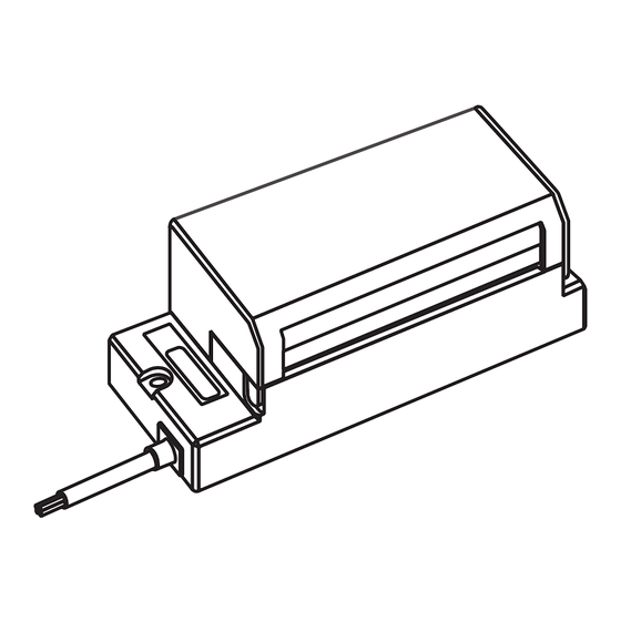
AnyWireASLINK System Products Guide
ASLINKTERMINAL
BL296□B-16F□-4A-20
■ Note on use ⇒A separate Address Writer is required to set addresses and other data.
*
For more information, refer to [Various Settings] on page 9.
[Type]
BL296SB-16F-4A-20
BL296XB-16F-4A-20
BL296PB-16F-4A-20
[Notes on Safety]
Precautions that must be observed in order to use this system safely are indicated as shown below.
You must observe these precautions.
A WARNING indicates a potentially hazardous
WARNING
situation which, if not handled correctly, could
result in death or serious injury.
○ System Safety
WARNING
This system is intended for general industrial applications. It does not have functions for supporting applications requiring higher
levels of safety such as safety-related devices or accident prevention systems. The product must not be used for these purposes.
○ Always turn off the power in installing or replacing the system.
○ Prolonged continuous ow of a rated load current or higher or a transit current due to load short-circuit, etc., in the hybrid unit including
the output unit and the output circuit may result in smoking or ring. An external safety device such as a fuse must be installed.
○ System power supply
CAUTION
Use a stable, 24V DC power supply. Use of an unstable power supply may cause problems with the system.
○ Separately route high-voltage and power cables
Although the AnyWireASLINK has a high noise margin, install the transmission line and I/O cables away from high-voltage and power
cables.
○ Connectors and terminals
- Pay careful attention to the length and installation of cable wiring to ensure that connectors and cables are neither overloaded nor disconnected.
- Make sure to prevent any metal objects from getting inside the connectors or the terminal blocks.
- Short-circuits caused by metal objects or mis-wiring are likely to damage the device.
○ Do not impose any external loads on the units. Doing so may cause a failure.
○ Do not disconnect or reconnect between the transmission line and slave units when the transmission line is active. A malfunction may occur.
○ Use the AnyWireASLINK within the range of the speci cations and conditions shown below.
[Warranty]
■ Warranty period
The warranty on the delivered Product shall continue to be effective for one (1)
year after the delivery thereof to a location as designated by the original owner.
■ Scope of warranty
Should a defect occur in any part of the Product during the foregoing warranty
period when it is used normally in accordance with the speci cations described
in this Products Guide, the Company shall replace or repair the defect free of
charge, except when it arises as a result of:
[1] Misuse or abuse of the Product by the owner;
[2] Fault caused by other than the delivered Product;
[3] The unauthorized modi cation or repair of the Product by any person other
than the Company's personnel;
[4] Any unusual force of nature, disaster or other cause beyond the Company's
control.
The term "warranty," as used herein, refers to the warranty applicable to the
delivered product alone. The Company shall not be liable for consequential or
incidental damages resulting from any malfunction.
■ Repair at cost
After the expiration of the warranty period, the owner shall be responsible for all
costs and expenses incurred for the troubleshooting and repair of the Product.
Even during the warranty term, the Company shall repair any defects arising
from causes other than within the scope of the warranty as speci ed above, at
the owner's cost.
■ Changes in the product speci cations and the descriptions in the manual
The descriptions in this manual may be subject to change without notice.
[ ASLINK Integrated Compact Terminal ]
NPN input
e-CON
NPN input/NPN output
(4 poles)
NPN output
-BL296*B16F*4A20 1/17-
BL296SB-16FS-4A-20
BL296XB-16FS-4A-20
BL296PB-16FS-4A-20
A CAUTION indicates a potentially hazardous situation
CAUTION
which, if not handled correctly, may result in personal
injury or property damage.
[About Pictogram *
Ver. 1.0*
*
1 The pictogram may not be marked (or stuck) depending on the product.
*
2 AnyWireASLINK device not compatible with Ver. 1.1 (word transmission and
single unit simplified replacement functions)
Some products, not marked with the Ver. 1.1 pictogram, are compatible with
the functions included in Ver. 1.1. Refer to the lot No. and the product guide
for ultimate confirmation.
*
3 For details of Ver. 1.1, refer to the subsequent pages.
PNP input
e-CON
PNP input/PNP output
(4 poles)
PNP output
]
1
Compatible with
2
Ver. 1.1*
Ver.1.1
3
Advertisement

Subscribe to Our Youtube Channel
Related Manuals for Anywire AnyWireASLINK BL296PB-16F-4A-20

Summary of Contents for Anywire AnyWireASLINK BL296PB-16F-4A-20
- Page 1 AnyWireASLINK System Products Guide Ver.1.1 ASLINKTERMINAL [ ASLINK Integrated Compact Terminal ] BL296□B-16F□-4A-20 ■ Note on use ⇒A separate Address Writer is required to set addresses and other data. For more information, refer to [Various Settings] on page 9. [Type] BL296SB-16F-4A-20 NPN input BL296SB-16FS-4A-20...
- Page 2 [About AnyWireASLINK Ver. 1.1] New functions have been added to AnyWireASLINK products in May 2019 onward. Also, for the purpose of differentiation of compatible functions, indication of product lot number (lot No.) has been changed. Compatible functions vary depending on lot No. Please understand the following description thoroughly to use each product.
- Page 3 [About Single Unit Simplified Replacement] During replacement of a slave unit, this function enables automatic settings of address and parameters of the existing slave unit into a new slave unit. (After replacement of the slave unit, address and parameter setting procedure using the address writer is not required.) ■Step 1 Turn OFF the 24V DC power supply for the master unit.
- Page 4 [Functions] ■Function list Model Speci cations Connection targets Functions Address Single unit Remote Detection of Word NPN input: 16 points, Word ASLINKTERMINAL sensor cable address simpli ed address address General-purpose NPN output: 16 points transmission transmission 4-wire (isolated) type setting replacement change disconnection...
- Page 5 [How to Connect AnyWireASLINK] The AnyWireASLINK can employ a two-wire or four-wire terminal selectively depending on the load current. If the load current is small, using a two-wire (non-isolated) terminal allows for achieving simpli ed wiring without local power supply. In the case of prioritizing the sites of concentrated loads and/or the number of connections, hybridization with a four-wire (isolated) terminal, which supports local power supply, is also possible.
- Page 6 Product Type Allowable power current ASLINK lter ANF-01 MAX 5A/24V DC Filter of COSEL Co., Ltd. EAC-06-472 MAX 6A/24V DC ■AnyWire Type: ANF-01 Connection example ①Power supply to the entire system 2-wire 4-wire 4-wire terminal terminal terminal AnyWireASLINK master POWER IN...
- Page 7 ■COSEL Co., Ltd. Type: EAC-06-472 Connection example ① Power supply to the entire system 2-wire 4-wire 4-wire terminal terminal terminal AnyWireASLINK master LOAD LINE Terminator EAC-06-472 If the total length of the section where all the DP, DN, 24V, and 0V lines run in parallel is more than 50m General-purpose power supply lter (Use it if necessary.)
- Page 8 [Name of Each Part] Setting port e-CON compliant 4P socket ■Side Black: DN Red: DP White: 0V Green: 24V Lot label LED indicators Transmission line 1 Prepare the connector separately. [Pin Assignment] e-CON compliant 4P socket IN 0 1 2 3 4 5 6 7 1: 24V BL296SB-16F-4A-20 2: N/C...
-
Page 9: Address Setting
[Various Settings] Address setting ■Common procedure for address writer operation Be sure to connect to the AnyWireASLINK master unit to use. ARW-04 (address writer) of Rev. (Ver.) 1.01 or later version, or ARW-03 of Rev. (Ver.) 2.10 or later version is required for address setting. For the details of the operating method, refer to the product guide of the address writer. - Page 10 [Data Configuration] BL296SB-16F-4A-20, BL296SB-16FS-4A-20 n = Bit address number assigned to this unit Address n+15 n+14 n+13 n+12 n+11 n+10 offset Bit input IN15 IN14 IN13 IN12 IN11 IN10 BL296PB-16F-4A-20, BL296PB-16FS-4A-20 Address n+15 n+14 n+13 n+12 n+11 n+10 offset OUT15 OUT14 OUT13 OUT12 OUT11...
- Page 11 [Troubleshooting] < LINK does not ash > Things to be checked Remedy Check the connection of this unit. Disconnect this unit once, and then reconnect it. Check conditions of the master unit 1) If LINK on the master unit is ashing and LINK on the slave unit is lit, it is possible that the master and slave unit.
- Page 12 [E.g.] 0V (White) Use the device by connecting the 0V 4-wire (isolated) ASLINK terminal Load driven by lines together. (Power supply of the AnyWire system) an external power supply 4-wire (isolated) NPN output BL296PB-16F-4A-20 BL296XB-16F-4A-20 (Output) To connect 24V (1)
- Page 13 [E.g.] 0V (White) Use the device by connecting the 0V 4-wire (isolated) ASLINK terminal Load driven by lines together. (Power supply of the AnyWire system) an external power supply 4-wire (isolated) PNP output BL296PB-16FS-4A-20 BL296XB-16FS-4A-20 (Output) <Circuit conditions> 24V (Green)
- Page 14 [Specifications] ■Individual speci cations ■General speci cations Number of BL296SB-16F-4A-20 NPN bit input: 16 points Operating ambient temperature/humidity 0 – +55°C, 10 – 90%RH No condensation occupied BL296XB-16F-4A-20 NPN bit input: 8 points/ Storing ambient temperature/humidity -25 – +75°C, 10 – 90%RH No condensation points bit output: 8 points Vibration resistance...
- Page 15 [Outside Dimensions] Unit: mm 3.25 84.5 3.25 11.6 2-φ3.5 19.25 (57) UL style 20276 4-wire × AWG23 (gray) φ4.6 49.8 41.2 (200) ■ADP-W96 (dedicated DIN rail mounting adaptor) * Optionally available ● Dimensions of adaptor ● Structural drawing Terminal engaging hook (at 4 places) Fastening hook Fastening hook Spring hook...
- Page 16 ● DIN rail mounting procedure 1. Set the ADP-W96 adaptor on the DIN rail. Orientation of ADP-W96 should be changed depending on whether the terminal is mounted in parallel with the rail or at right angles to the rail. - When the terminal is mounted in parallel with the rail - When the terminal is mounted at right angles to the rail Spring hook Spring hook...
- Page 17 [Address] Anywire Corporation Headquarters :1 Babazusho, Nagaokakyo-shi, Kyoto 617-8550 JAPAN Contact :Contact by mail info_e@anywire.jp :Contact by website http://www.anywire.jp Printed in Japan 2016,2017,2018,2019,2020 UMA-13221AI-EN -BL296*B16F*4A20 17/17-...
Need help?
Do you have a question about the AnyWireASLINK BL296PB-16F-4A-20 and is the answer not in the manual?
Questions and answers