Advertisement
Quick Links
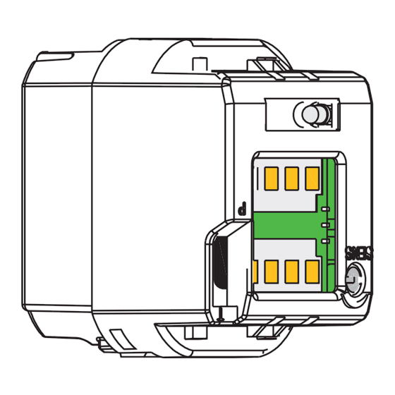
DESCRIPTION
SINGLE-GANG
1
TECHNICAL SPECIFICATIONS
Technology:
Radiated frequency:
Radiated power density:
Supply voltage:
Supply frequency:
Power consumption:
Output
relay contact rating (max. voltage):
relay contact rating (max. current):
Max. switching power:
Detection range:
Detection mode:
Output hold time:
Temperature range:
Immunity:
Weight:
Material:
Certification:
75.5265.05 MS08 20180913
4
4
3
microwave motion sensor
24.125 GHz
5 mW/cm
12 – 24 VAC ±10%
12 – 24 VDC +30% / -10%
50 – 60 Hz
< 1.5W
relay with switch-over contact (voltage-free)
60 VDC / 125 VAC
1A (resistive)
30W DC / 60 VAC
4 – 24" (adjustable)
motion (bidirectional)
0.5 sec (in pulsed mode)
-4 – 131 °F (-20 – 55 °C)
immune to electrical and radio frequency interference
0.34 lbs
ASA, nylon, PC
Electromagnetic compatibility (EMC) according to 2004/108/EC
FCC: G9B-MS08
IC: 4680A-MS08
MS08 MAGIC SWITCH
Microwave, contactless switch for automatic doors
DOUBLE-GANG
1
1. Microwave motion sensor
2. Adapter ring
3. Faceplate
4. Screws
2
Specifications are subject to change without prior notice.
All values measured in specific conditions.
2
3
4
4
Page 1 of 4
Advertisement

Subscribe to Our Youtube Channel
Related Manuals for BEA Obsolete MAGIC SWITCH MS08


Summary of Contents for BEA Obsolete MAGIC SWITCH MS08
- Page 1 MS08 MAGIC SWITCH Microwave, contactless switch for automatic doors DESCRIPTION SINGLE-GANG DOUBLE-GANG 1. Microwave motion sensor 2. Adapter ring 3. Faceplate 4. Screws TECHNICAL SPECIFICATIONS Technology: microwave motion sensor Radiated frequency: 24.125 GHz Radiated power density: 5 mW/cm Supply voltage: 12 –...
- Page 2 *Connect the equipment into an outlet on a circuit different from that to which the receiver is connected *Consult the dealer or an experienced radion/TV technician for help WARNING: CHANGES OR MODIFICATIONS TO THIS EQUIPMENT NOT EXPRESSLY APPROVED BY BEA INC. MAY VOID THE FCC AUTHORIZATION TO OPERATE THIS EQUIPMENT.
- Page 3 WIRING 1. Wire the 4-conductor cable to the door operator according to manufacturer specifications (see appendix for wiring diagrams). 2. Attach the 4-conductor cable connector NC NO COM POWER to the Touchless Actuator (see right). NO COM POWER SET-UP Two adjustments can be made to the sensor. The potentiometer is used to adjust the size of the unit’s sensing field (see below, left) and the Output Mode switch is used to select Toggle or Pulse mode (see below, right).
- Page 4 BEA strongly recommends that installation and service technicians be AAADM-certifi ed for pedestrian doors, IDA-certifi ed for doors/gates, and factory- trained for the type of door/gate system.
Need help?
Do you have a question about the Obsolete MAGIC SWITCH MS08 and is the answer not in the manual?
Questions and answers