Table of Contents
Advertisement
Quick Links
Advertisement
Table of Contents

Subscribe to Our Youtube Channel
Related Manuals for KERN KIP-V20


Summary of Contents for KERN KIP-V20
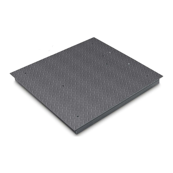
- Page 1 KERN & Sohn GmbH Ziegelei 1 Phone: +49-[0]7433- 9933-0 D-72336 Balingen Fax: +49-[0]7433-9933-149 E-Mail: info@kern-sohn.com Internet: www.kern-sohn.com Installation instructions weighing bridge KERN KIP_V20 Version 1.0 2017-09 KIP-V20-IA-e-1710...
-
Page 2: Table Of Contents
KERN_KIP V20 2017-09 Version 1.0 Installation instructions weighing bridge Contents General ......................3 Technical data ....................3 Basic Information (General) ................4 Documentation ........................... 4 Proper use ..........................4 Improper Use ..........................4 Warranty ............................. 4 Monitoring of Test Resources ....................5 Basic Safety Precautions ................ -
Page 3: General
1 General These installation instruction contain all data necessary for placing and commissioning the following weighing bridges: KIP 600V20SM KIP 600V20M KIP 1500V20SM KIP 1500V20M KIP 1500V20EM KIP 3000V20M KIP 3000V20LM 2 Technical data Model Weighing Readability Verificati Minimum Cable range on value load... -
Page 4: Basic Information (General)
The weighing system unit may only be operated in accordance with the described default settings. Other areas of use must be released by KERN in writing. 3.4 Warranty Warranty claims shall be voided in case •... -
Page 5: Monitoring Of Test Resources
In KERN's accredited DKD calibration laboratory test weights and weighing systems may be calibrated (return to the national standard) fast and at moderate cost. -
Page 6: Unpacking, Setup And Commissioning
6 Unpacking, Setup and Commissioning 6.1 Installation Site, Location of Use The weighing bridges are designed in a way that reliable weighing results are achieved in common conditions of use. You will work accurately and fast, if you select the right location for your weighing system. -
Page 7: Unpacking, Scope Of Delivery
6.2 Unpacking, Scope of delivery Danger for the back! The weighing bridge is relatively heavy. Always use a suitable lifting device to lift it out of the packaging or to transport it to the required installation site. CAUTION Do not step under the suspended load, risk of injury! 1. -
Page 8: Assembly, Levelling
6.3 Assembly, levelling Accurate weighing results require a weighing bridge with perfect horizontal alignment. During initial installation and after each change of work area it is necessary to level the weighing bridge. Placing the weighing bridge: 1. Prior to the final placing, install the four weighing cell feet. 2. -
Page 9: Connecting A Display Unit
6.4 Connecting a display unit Attention Put the connecting cable to the display unit in a manner that it is protected against damage. Description of the connection cable: terminal Color State EXC+ [IN+] voltage + SIG + [OUT+] green signal + SIG -[OUT-] white signal -... -
Page 10: Operation Limits
7.1 Operation limits • The weighing bridges are designed extremely robust. However the load limits according to the following table should not be exceeded! • Depending on the type of load receptacle, the static carrying capacity, i.e. the maximum admissible load is: Weighing ranges 600kg 1500kg 3000kg... -
Page 11: Service, Maintenance, Disposal
Do not use water jet or high-pressure cleaner. 8.3 Service, maintenance The appliance may only be opened by trained service technicians who are authorized by KERN. Ensure that the weighing system is regularly calibrated, see chap. 3.5 Testing instruments control. -
Page 12: Instant Help
8.5 Instant help In case of an error in the program process, briefly turn off the balance and disconnect from power supply. The weighing process must then be restarted from the beginning. Help: Fault Possible cause • Draught/air movement The displayed weight is permanently changing •... -
Page 13: Service Documentation
9 Service documentation • This chapter is only intended for a balance specialist! • The weighing bridges are carried out in DMS sensor technology, at every corner a DMS weighing cell is installed. • The analogue-digital transformation occurs in the display unit. Also all the balance and country-specific data are stored there. - Page 14 Verification data and tolerances as per OIML 600kg [kg] -0,1 -0,2 -0,3 -0,4 1500kg 0,75 0,25 [kg] -0,25 -0,5 -0,75 1000 1500 3000kg [kg] -0,5 -1,5 1000 2000 3000 KIP_V20-IA-e-1710...
-
Page 15: Check And Adjustment Of The Corner Load
9.2 Check and adjustment of the corner load Check of the corner load: • Place the test weights in the centre of the load plate and tare. • The balance displays -0-. • Place the test weights successively on all four corners. - Page 16 Adjustment on the analogue print Connection box Weighing cell 1 Weighing cell 2 Weighing cell 3 Weighing cell 4 Adjustment of weighing cell CN1 takes place at the potentiometer VR1 Adjustment of weighing cell CN2 takes place at the potentiometer VR2 Adjustment of weighing cell CN3 takes place at the potentiometer VR3 Adjustment of weighing cell CN4 takes place at the potentiometer VR4 Increase the value turning to the right, reduce the value turning to the left.
Need help?
Do you have a question about the KIP-V20 and is the answer not in the manual?
Questions and answers