Table of Contents
Advertisement
Quick Links
Instructions
E70/E60 King
Electric driver for application of protective coatings. For professional use only.
Not approved for use in explosive atmospheres or hazardous (classified) locations.
Important Safety Instructions
Read all warnings and instructions in this
manual and in related manuals before
using the equipment. Save these
instructions.
Model 25P291
®
Electric Driver
3A8478A
EN
Advertisement
Table of Contents

Related Manuals for Graco King E70


Summary of Contents for Graco King E70
- Page 1 Instructions 3A8478A ® E70/E60 King Electric Driver Electric driver for application of protective coatings. For professional use only. Not approved for use in explosive atmospheres or hazardous (classified) locations. Important Safety Instructions Read all warnings and instructions in this manual and in related manuals before using the equipment.
-
Page 2: Table Of Contents
Standby Mode ......12 Graco Extended Warranty ....30 Error Codes Table . -
Page 3: Warnings
Warnings Warnings The following warnings are for the setup, use, grounding, maintenance, and repair of this equipment. The exclamation point symbol alerts you to a general warning and the hazard symbols refer to procedure-specific risks. When these symbols appear in the body of this manual or on warning labels, refer back to these Warnings. Product-specific hazard symbols and warnings not covered in this section may appear throughout the body of this manual where applicable. - Page 4 Warnings WARNING MOVING PARTS HAZARD Moving parts can pinch, cut or amputate fingers and other body parts. • Keep clear of moving parts. • Do not operate equipment with protective guards or covers removed. • Equipment can start without warning. Before checking, moving, or servicing equipment, follow the Pressure Relief Procedure and disconnect all power sources.
- Page 5 Warnings WARNING PERSONAL PROTECTIVE EQUIPMENT Wear appropriate protective equipment when in the work area to help prevent serious injury, including eye injury, hearing loss, inhalation of toxic fumes, and burns. Protective equipment includes but is not limited to: • Protective eyewear, and hearing protection. •...
-
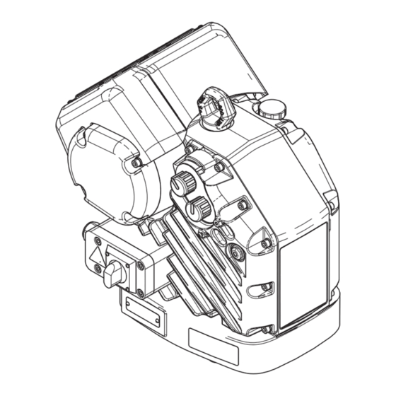
Page 6: Component Identification
Component Identification Component Identification Ref. Description Ref. Description Oil Fill Cap (vented) Driver Power Switch (Lock-out tag-out equipped) Lift Ring Electrical Junction Box Oil Drain Plug Electrical Junction Box Cover Driver Output Shaft Ground Screws Oil Sight Glass Cord Grip (for Power Cord) Status Indicator Light (LED) Cord Grip (for Fan Cable) Mode Selector Knob... -
Page 7: Installation
Installation Installation NOTE: The two fan harness wires will be installed in disconnect block (J) in both 1L1 and 3L2 terminals. Improper wiring may cause electric shock or other serious injury. All electrical wiring must be done by a qualified electrician and comply with all local codes and regulations. -
Page 8: Grounding
Installation Grounding 7. Replace junction box screws and washers removed in step 2 and tighten cord grip (X1) to securely hold power cord in junction box (Y). See F . 4. The equipment must be grounded to reduce the risk of static sparking and electric shock. -
Page 9: Operation
Operation Operation Startup 1. Perform Installation procedures starting on page 7. 2. Turn the pressure control knob (N) fully counterclockwise to 0. 3. Connect the power cord to a power source. 4. Pull mode selector knob (M) out and set it to the . -
Page 10: Pressure Relief Procedure
Operation Pressure Relief Procedure Driver Operation Follow the Pressure Relief Procedure Pressure Control whenever you see this symbol. The driver will adjust the speed to maintain a constant fluid pressure. 1. Pull the pressure control knob (N) out to set. 2. -
Page 11: Maintenance
Maintenance Maintenance 3. Open the oil fill cap (P) and add Graco Part 16W645 NOTICE ISO 220 silicone-free synthetic EP gear oil. Check Do not open/remove gear cover. The gear side is not the oil level in the sight glass (K). (See F . -
Page 12: Troubleshooting
Troubleshooting Troubleshooting NOTE: To clear an error code, cycle power by turning the power switch (S) to the OFF position for at least 30 seconds before turning back ON. Standby Mode When slow blinking is displayed, the driver has entered Standby Mode. - Page 13 Troubleshooting Blink Code Error Type Troubleshooting Steps Deviation High Temperature The temperature of the system is near the maximum operation temperature. The performance has been reduced to prevent the driver from completely shutting down. • Check fan operation. Clean the fan and driver housing. •...
-
Page 14: Repair
Replace Output Seal Cartridge 4. Unscrew fuse holder, remove old fuse, and replace with new fuse (Graco part number 116682) (5 mm x 1. Stop pump at the top of its stroke. Shut off and 20 mm, 500 mA, 250V, Slow Blow). Reconnect fuse disconnect power to driver. -
Page 15: Remove Fan Shroud
Repair Remove Fan Shroud 4. Loosen terminal screws for 1L1 and 3L2 and gently remove wires from each location. 1. Disconnect the unit from the power source. 2. Remove screws (56, 24) that attach the fan assembly to driver and pull up on end farthest from junction box. -
Page 16: Reinstall Fan Wires
Repair Reinstall Fan Wires Replace Electronics Cover 1. Route wires through fan cord grip (82) attached to Removal driver (see F . 13 on page 15). 1. Follow the Pressure Relief Procedure on page 10. 2. Reattach the ground wire to the upper grounding 2. - Page 17 Repair 7. Carefully separate the electronics cover (3) from the 9. Disconnect the stroke position sensor (29). driver, then disconnect the wires. . 17: Remove Electronics Cover NOTICE All wires must be disconnected before the cover is . 19: Stroke Position Sensor completely removed.
- Page 18 Repair Installation Calibration NOTE: The lower must be removed from the driver in 1. Reconnect all wires: order to calibrate the driver correctly. The calibration • Motor power and motor temperature sensor. See stroke length is longer than the operating stroke. .
-
Page 19: Replace Stroke Position Sensor
(see Wiring Diagrams, page 27). To avoid damage to the electronic components, wear 2. Loosen the stroke position sensor jam nut using a grounding strap (Graco part 112190 - not supplied) 13 mm wrench. and ground appropriately. 3. Unscrew the stroke position sensor (29) from the Overview center housing using a 6 mm open ended wrench. -
Page 20: Replace Encoder
Repair Replace Encoder Reinstall Electronics Cover onto Driver Overview The encounter is used by the driver for two purposes. First, the encoder tells the control board where the Make sure wires are not pinched when re-installing motor is in its mechanical rotation and uses that covers. - Page 21 Repair Remove Encoder Install New Encoder 1. Loosen the two hub set screws (AA) using the 1. Plug the encoder connector (AE) and control board included 0.050 in. hex wrench. connector (AF) into the encoder (21). If replacing the encoder cable also, place the encoder 2.
-
Page 22: Repair Token Cable
Repair Repair Token Cable NOTE: The junction box does not need to be removed or disassembled. 1. Follow the Pressure Relief Procedure on page 10. 6. Carefully remove electronics cover (3). 2. Disconnect unit from power source. See F . 17, page 17. 3. -
Page 23: Software Update Procedure
NOTE: The token can remain in place even after the . 31: Remove Motor Cover software has been updated. 10. The latest software version for each system can be found at www.graco.com. 3A8478A... -
Page 24: Parts
Parts Parts Electric Driver . 33: Electric Driver Parts 3A8478A... -
Page 25: Parts List - Electric Driver (25P291)
Parts Parts List - Electric Driver (25P291) Ref. Part Description Qty. Ref. Part Description Qty. 24V290 COVER, fan, assembly, with wire - - - - - HOUSING, main harness - - - - - COVER, gear [includes Ref. 24 (3x), 43 (3x), 56 (2x), 92 (2x), 94 (2x)] 25P489 KIT, electronics, non-haz, E70... -
Page 26: Mounting Hole Pattern
Parts Mounting Hole Pattern . 34: Mounting Hole Pattern 6.186 in. 6.186 in. Four 3/8-16 Six 5/8-11 Tie Rod Holes: (157 mm) (157 mm) Mounting Holes 8 in. (203 mm) x 120° bolt circle 5.9 in. (150 mm) x 120° bolt circle 3A8478A... -
Page 27: Wiring Diagrams
Wiring Diagrams Wiring Diagrams AIR FLOW DIRECTION ti36492a ti36494a . 35: Wiring Diagram Ref. Description Ref. Description Stroke position sensor wire Motor temperature sensor wires Circuit board power wires Motor wires Fan power wires Token cable Fan fuse holders Encoder cable Incoming power 3A8478A... -
Page 28: Dimensions
Dimensions Dimensions Driver Dimensions Width 15.3 in. (38.8 cm) Depth 18.3 in. (46.5 cm) Mounted Height 18.3 in. (46.5 cm) Total Height 21.5 in. (54.6 cm) 3A8478A... -
Page 29: Technical Specifications
6.5 kW (5 kW for 100-120 V) Oil capacity† 1.5 quarts 1.4 liters Oil specification† Graco part number 16W645 ISO 220 silicone-free synthetic EP gear oil† Maximum dynamic force 4650 lbf 21 kN Sound Emissions for Normal Operation (<20 cpm) Sound Pressure* <80 dBA... -
Page 30: Graco Extended Warranty
With the exception of any special, extended, or limited warranty published by Graco, Graco will, for a period of twelve months from the date of sale, repair or replace any part of the equipment determined by Graco to be defective.
Need help?
Do you have a question about the King E70 and is the answer not in the manual?
Questions and answers