Graco 25C453 Instructions Manual
Electric direct drive agitators
Hide thumbs
Also See for 25C453:
- Instructions - parts manual (23 pages) ,
- Instructions manual (20 pages) ,
- Instructions and parts (30 pages)
Table of Contents
Advertisement
Quick Links
Instructions - Parts
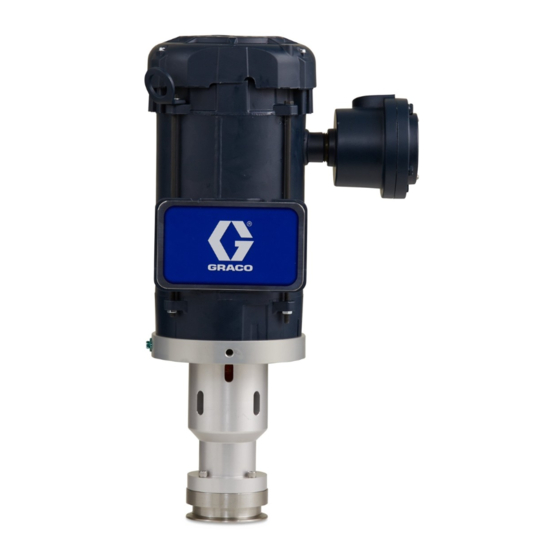
Electric Direct Drive Agitators
Low shear, electric, direct drive agitator for mixing and maintaining suspension of industrial coatings
stored in fluid tanks. For professional use only.
Important Safety Instructions
Read all warnings and instructions in this manual and associated
component manuals. Save all instructions.
See page 3 for a complete list of model
descriptions and part numbers.
PROVEN QUALITY. LEADING TECHNOLOGY.
3A4553A
EN
Advertisement
Table of Contents

Related Manuals for Graco 25C453


Summary of Contents for Graco 25C453
- Page 1 Instructions - Parts Electric Direct Drive Agitators 3A4553A Low shear, electric, direct drive agitator for mixing and maintaining suspension of industrial coatings stored in fluid tanks. For professional use only. Important Safety Instructions Read all warnings and instructions in this manual and associated component manuals.
-
Page 2: Table Of Contents
Installation........7 Parts — Flange Mount ........12 Electrical Connections ........8 Parts — Quick-Clamp Mount ......14 Graco Motor Control........8 Parts — Pressure Tank Mount ......16 Grounding the Agitator ......... 8 Notes ..............18 Operation ............9 General Operation ........ -
Page 3: Models
The Agitator requires power from a variable frequency drive to control speed and are not to be used without a speed control installed. See manual 3A4793 for listing of VFD motor controls ordering information. Table 1 UL Listed Explosion Proof Inverter Duty Motor Part No. Description 25C453 3" Quick-clamp Flange Mount Agitator 25C575 4” Quick-clamp Flange Mount Agitator 25C454 7.5"... -
Page 4: Warnings
Warnings Warnings The following warnings are for the setup, use, grounding, maintenance, and repair of this equipment. The exclamation point symbol alerts you to a general warning and the hazard symbols refer to procedure-specific risks. When these symbols appear in the body of this manual or on warning labels, refer back to these Warnings. Product-specific hazard symbols and warnings not covered in this section may appear throughout the body of this manual where applicable. - Page 5 Warnings WARNING EQUIPMENT MISUSE HAZARD Misuse can cause death or serious injury. • Do not operate the unit when fatigued or under the influence of drugs or alcohol. • Do not exceed the maximum working pressure or temperature rating of the lowest rated system component.
-
Page 6: Installation
Installation Installation NOTE: The impeller may be relocated on the shaft as needed, up to 1.5 times the impeller diameter. Shaft and Impeller Size Flange-mounted agitators need shafts and blades. See Table 3 to determine the length of the shaft and recommended impeller diameter. -
Page 7: Motor, Bearing Housing, And Impeller
(not provided) and Mounting the flange (3 methods): existing quick-clamp flange on tank. Attach • (3) holes to mount to Graco drum lids that have with clamp (not provided) and tighten mounting surface for back-gear agitator housings. securely. -
Page 8: Electrical Connections
Installation Graco Motor Control 7. Place alignment coupling (8) on top. 8. Fasten motor flange (10) to bearing housing with See manual 3A4793 for information on motor control 4 cap screws (5). installation and operation. a. For ATEX motors: Attach the adapter flange (30) to the motor (12) with 4 bolts (31). -
Page 9: Operation
fluid. 3. Reduce the speed slightly, then fill the fluid container. If using a Graco supplied VFD, the agitator speed can be calculated by using the formula below. Example 1: (AIB) x C = D... -
Page 10: Service
Service Service 8. Complete the procedure by following the steps in Motor, Bearing Housing, and Impeller Installation, page 7 • Moving parts, such as an impeller blade, can pinch or amputate fingers. To reduce risk of injury or damage to equipment, always disconnect power from the agitator before performing maintenance or service. -
Page 11: Notes
Notes Notes 3A4553A... -
Page 12: Parts - Flange Mount
Parts — Flange Mount Parts — Flange Mount Models 25C454 and 25C463 3A4553A... - Page 13 Parts — Flange Mount Part MOTOR, UL Listed, Description 3/4,230/460, TEFC, 17N543 XP, 60 HZ (model ASSEMBLY, 25C454) BEARING HOUSING/FLANGE MOTOR, ATEX, 0.37 kW, 230/400, TEFC, FLANGE,DD,LID,3" 17P074 17N898 XP, 50 HZ (model 150# MOUNTING 25C463) 17N588 SEAL, PTFE SCREW, CAP, C19837 SPACER, SEAL, SOCKET...
-
Page 14: Parts - Quick-Clamp Mount
Parts — Quick-Clamp Mount Parts — Quick-Clamp Mount Models 25C453, 25C575, 25C464, 25C576 3A4553A... - Page 15 16P923 ALIGNMENT, 0.62” BORE DIAMETER SCREW, SET FLANGE, MOTOR, 17N899 MOUNT MOTOR, UL LISTED, 17N543 3/4,230/460, TEFC, XP, 60 HZ (model 25C453 and 25C575) MOTOR, ATEX, 0.37 kW, 230/400 17P074 V, TEFC, XP 50 HZ (model 25C464 and 25C576) 3A4553A...
-
Page 16: Parts - Pressure Tank Mount
Parts — Pressure Tank Mount Parts — Pressure Tank Mount Models 25C462, 25C470, 25C471, 25C465, 25C472, 25C473 3A4553A... - Page 17 Parts — Pressure Tank Mount Part SCREW, CAP, Description C19837 SOCKET ASSEMBLY, SCREW, WING (Not 17P459 BEARING Shown) HOUSING/FLANGE 17N542 WASHER, LOCK, SS FLANGE, 188784 17N900 AGITATOR, IMPELLER — 4”,KIT PRESSURE TANK (models 25C462, 17N588 SEAL, PTFE 25C470, 25C465, 25C472) SPACER, SEAL, 17N704 15Y360...
-
Page 18: Notes
Notes Notes 3A4553A... -
Page 19: Technical Data
Technical Data Technical Data Electric Direct Drive Agitators EXPLOSION PROOF CLASS 1 Group C&D Motor, UL (models 25C483, 25C485, 25C486) CLASS 2 Group F&G T3C UL motor = 3/4 hp; Motor Power ATEX motor = 0.37 kW UL motor 230/460 VAC, 60 Hz, 3 Phase Motor Electrical Requirements ATEX motor 230/400 VAC, 50 Hz, 3 Phase Maximum Recommended Agitator Shaft Speed... - Page 20 With the exception of any special, extended, or limited warranty published by Graco, Graco will, for a period of twelve months from the date of sale, repair or replace any part of the equipment determined by Graco to be defective. This warranty applies only when the equipment is installed, operated and maintained in accordance with Graco’s written recommendations.
Need help?
Do you have a question about the 25C453 and is the answer not in the manual?
Questions and answers