Advertisement
Quick Links
Instructions
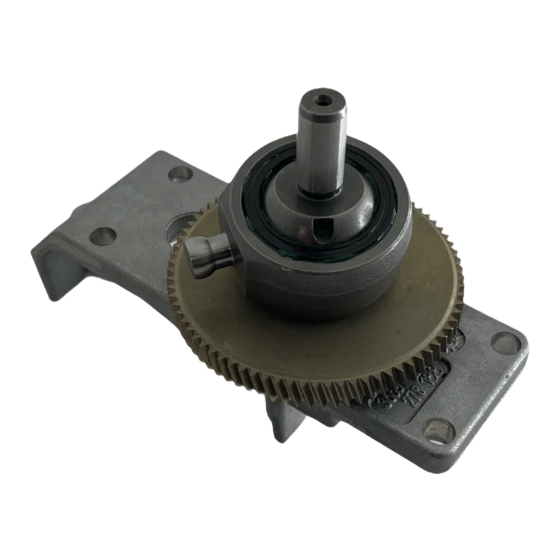
Gear/Drive Kit for Magnum X5, X7,
LTS 15, LTS 17 (Series B)
This manual contains kit installation instructions only
Kit: 16E778, 16E835
Important Safety Instructions
For detailed sprayer information and warnings,
see Operation manual 312001, 313034.
Pressure Relief Procedure
To help prevent injection injuries, follow this procedure
when you stop spraying and before you service or clean
the sprayer, remove parts, or repair leaks.
1. Turn Power switch OFF. Unplug sprayer.
2. Turn Spray/Prime valve to PRIME to relieve pressure. Turn
pressure control knob left (counterclockwise) to minimize
pressure.
3. Trigger gun.
4. Put trigger safety in safety ON position.
NOTE: Leave Spray/Prime valve in PRIME
position until you are ready to spray again.
If you suspect that the spray tip or hose is completely clogged or
that pressure has not been fully relieved after following the steps
above, VERY SLOWLY loosen the tip guard retaining nut or hose
end coupling to relieve pressure gradually. Then loosen it com-
pletely. Clear the tip or hose obstruction.
ti11868a
3A0978A
ENG
ti15766a
Advertisement

Related Manuals for Graco 16E778


Summary of Contents for Graco 16E778
- Page 1 Gear/Drive Kit for Magnum X5, X7, 3A0978A LTS 15, LTS 17 (Series B) This manual contains kit installation instructions only Kit: 16E778, 16E835 Important Safety Instructions For detailed sprayer information and warnings, see Operation manual 312001, 313034. Pressure Relief Procedure...
- Page 2 Disassembly 14. Pull the drive assembly and pump piston from the pump. If necessary, tap on the shorter leg of the drive with a plastic hammer to separate the parts. Icons only table sample NOTICE ELECTRIC SHOCK HAZARD MOVING PARTS HAZARD To reduce risk of serious injury, including electric Prying between the pump and drive can damage the shock, do not touch moving or electrical parts with...
- Page 3 10. Route the power cord and motor leads between the to 20-25 in-lb. X7 and LTS 17 Only: Install under- motor and right shroud (H). Then connect all leads side shroud screw (E) and tighten to 25-35 in-lb. to the control board (G). Press the strain relief on 12.
- Page 4 All written and visual data contained in this document reflects the latest product information available at the time of publication. Graco reserves the right to make changes at any time without notice. Original instructions. This manual contains English. MM 3A0984...
Need help?
Do you have a question about the 16E778 and is the answer not in the manual?
Questions and answers