Table of Contents
Advertisement
Quick Links
Advertisement
Table of Contents

Subscribe to Our Youtube Channel
Related Manuals for IFM Electronic efector500 PQ08 Series


Summary of Contents for IFM Electronic efector500 PQ08 Series
- Page 1 Operating instructions Pressure sensor PQ08xx...
-
Page 2: Table Of Contents
Contents 1 Preliminary note ���������������������������������������������������������������������������������������������������3 1�1 Symbols used ������������������������������������������������������������������������������������������������3 2 Safety instructions �����������������������������������������������������������������������������������������������3 3 Functions and features ����������������������������������������������������������������������������������������4 4 Function ���������������������������������������������������������������������������������������������������������������4 4�1 Processing of the measured signals ��������������������������������������������������������������4 4�2 Switching function ������������������������������������������������������������������������������������������4 4�3 Diagnostic function ����������������������������������������������������������������������������������������5 5 Mounting ��������������������������������������������������������������������������������������������������������������6 5�1 Mounting accessories ������������������������������������������������������������������������������������6 5�2 DIN rail mounting �������������������������������������������������������������������������������������������6 5�3 Rear panel mounting �������������������������������������������������������������������������������������7 6 Electrical connection ��������������������������������������������������������������������������������������������7... -
Page 3: Preliminary Note
10 Operation ���������������������������������������������������������������������������������������������������������16 10�1 Reading of the set parameters ������������������������������������������������������������������16 10�2 Fault indication ������������������������������������������������������������������������������������������16 11 Scale drawing ��������������������������������������������������������������������������������������������������17 12 Technical data ��������������������������������������������������������������������������������������������������18 12�1 Setting ranges �������������������������������������������������������������������������������������������19 13 Werkseinstellung ���������������������������������������������������������������������������������������������19 1 Preliminary note 1.1 Symbols used ► Instruction > Reaction, result […] Designation of pushbuttons, buttons or indications →... -
Page 4: Functions And Features
3 Functions and features The unit monitors the system pressure in pneumatic and compressed air networks of machines and plants� Applications Compressed air (other media on request) Type of pressure: relative pressure Permissible Order no. Measuring range Bursting pressure overpressure PQ0809 -1���1 -14�5���14�5 PQ0834 -1���10 -14�5���145 MPa = bar ÷ 10 / kPa = bar × 100 Avoid static and dynamic overpressure exceeding the given overload pres- sure by taking appropriate measures�... -
Page 5: 4�3 Diagnostic Function
• Window function / normally open: [oux] = [Fno] (→ fig. 2). • Window function / normally closed: [oux] = [Fnc] (→ fig. 2). The width of the window can be set by means of the difference between FHx and FLx� FHx = upper value, FLx = lower value� P = system pressure; HY = hysteresis; FE = window 4.3 Diagnostic function Output 2 is used as diagnostic output based on the DESINA specification if [ou2] = [diA]� • If there is no fault, the output is switched and carries Ub- � • In case of malfunctions in the following areas, the output is inactive: - short circuit in output 1�... -
Page 6: Mounting
5 Mounting Before installing and removing the unit: make sure that no pressure is applied to the system. ► Screw the pressure connection or adapter G⅛ to the main pressure connection (1) and tighten. Maximum tightening torque: 8 Nm. Maximum thread length: 7.5 mm. 5.1 Mounting accessories The following components are available as accessories: Order no. -
Page 7: 5�3 Rear Panel Mounting
Removal: ► Lever out the mounting clip with a screwdriver at the top or at the bottom and remove the unit� 5.3 Rear panel mounting ► Fix the unit with 2 screws M4 x 35 (1) (not included) to the rear panel� Maxi- mum tightening torque: 2�5 Nm�... -
Page 8: Operating And Display Elements
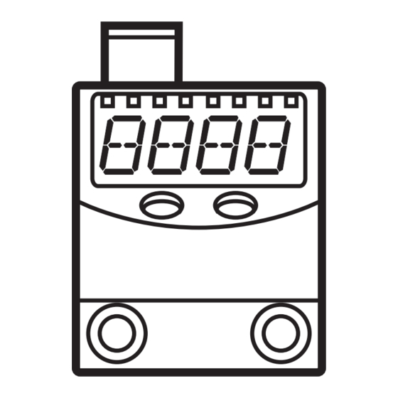
7 Operating and display elements 1 2 3 4 5 6 7 8 Mode/Enter Set 1 to 8: Indicator LEDs - LED 1 to LED 4 = system pressure in the unit of measurement which is indicated on the label� - LEDs 5 to 6: not used, - LED 7, LED 8 = switching state of the corresponding output�... -
Page 9: Menu
8 Menu 8.1 Menu structure... -
Page 10: 8�2 Explanation Of The Menu
8.2 Explanation of the menu SP1/rP1 Upper / lower limit value for system pressure at which OUT1 switches. FH1/FL1 Upper / lower limit for the acceptable range (monitored by OUT1). SP2/rP2 Upper / lower limit value for system pressure at which OUT2 switches. FH2/FL2 Upper / lower limit for the acceptable range (monitored by OUT2). Extended functions / opening of menu level 2� rES Restore factory settings� dS1 Time delay for SP1 / FH1. dS2 Time delay for SP2 / FH2. dr1 Time delay for rP1 / FL1. dr2 Time delay for rP2 / FL2. ou1 Output function for OUT1: • Switching signal for the pressure limit values: hysteresis function [H ��] or window function [F ��], either normally open [�... -
Page 11: Parameter Setting
9 Parameter setting During parameter setting the unit remains in the operating mode� It continues its monitoring function with the existing parameters until the parameter setting has been completed� 9.1 General parameter setting 3 steps must be taken for each parameter setting: Parameter selection ►... - Page 12 ► Press [Set] and keep it pressed until Mode/Enter Set the valid code no� is displayed� ► Press [Mode/Enter] briefly� On delivery by ifm electronic: no access restriction� ► Press [Set] briefly� > The first parameter of the sub-menu is displayed (here: [uni])�...
-
Page 13: 9�2 Setting Of The Output Signals
9.2 Setting of the output signals 9.2.1 Setting of the unit of measurement for system pressure ► Select [uni] and set the unit of measurement: [bAr], [kPa], [PSI], [inHg]� 9.2.2 Setting of the output function ► Select [ou1] and set the function: - [Hno] = hysteresis function / normally open - [Hnc] = hysteresis function / normally closed, - [Fno] = window function / normally open,... -
Page 14: 9�3 User Settings (Optional)
9.3 User settings (optional) 9.3.1 Setting of a time delay for the switching signals • [dS1] / [dS2] = time delay for SP1 / SP2 / FH1 / FH2�If the system pres- sure exceeds SPx or if the system pressure enters the acceptable range (window), the output changes the switching status when the time dSx has elapsed�... -
Page 15: 9�3�4 Zero Point Calibration
9.3.4 Zero point calibration ► Select [coF] and set a value between -5 % and 5 % of the measuring span. The internal measured value "0" is shifted by this value. As an alternative: automatic adjustment of the offset in the range 0 bar ± 5 % of the measuring span� ►... -
Page 16: Operation
10 Operation After power on, the unit is in the Run mode (= normal operating mode)� It carries out its measurement and evaluation functions and provides output signals accord- ing to the set parameters� Operating indications → chapter 7 Operating and display elements. 10.1 Reading of the set parameters ►... -
Page 17: Scale Drawing
11 Scale drawing Dimensions in mm 1: main pressure connection G 1/8; tightening torque max� 8 Nm maximum thread length: 7�5 mm� 2: for fixing screw M4; tightening torque max� 2�5 Nm 3: LEDs (display unit / switching status) 4: 4-digit alphanumeric display 5: programming button... -
Page 18: Technical Data
12 Technical data Operating voltage [V] ������������������������������������������������������������������������������������������18���32 DC Current consumption [mA] ��������������������������������������������������������������������������������������������� < 50 Current rating per switching output [mA] ������������������������������������������������������������������������ 100 Reverse polarity protection, overload protection ������������������������������������������������� up to 40 V Short-circuit protection; Integrated watchdog Voltage drop [V] �������������������������������������������������������������������������������������������������������������� < 2 Power-on delay time [s] ��������������������������������������������������������������������������������������������������... -
Page 19: 12�1 Setting Ranges
12.1 Setting ranges SPx / FHx rPx / FLx ΔP -0�98 1�00 -0�99 0�99 0�01 -14�2 14�6 -14�4 14�4 0�2 inHG -28�8 29�7 -29�1 29�4 0�3 -0�90 10�00 -0�95 9�95 0�05 1000 inHG ΔP = step increment 13 Werkseinstellung Factory setting User setting SP1/FH1 25% VMR* rP1/FL1...
Need help?
Do you have a question about the efector500 PQ08 Series and is the answer not in the manual?
Questions and answers