Table of Contents
Advertisement
Quick Links
M DM2
®
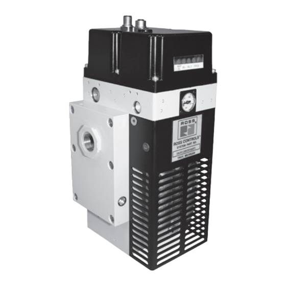
Double Valve with Integrated Soft Start
Thank You!
brake applications). The valve is designed for base mounting for ease of installation and maintenance. With
care in its installation and maintenance you can expect it to have a long and economical service life. Before
you install this valve, read the information in this folder completely, and save it for future reference.
NOTE: This valve is expressly not intended for use in press clutch/brake applications.
ROSS produces the DM
2®
press clutch/brake applications.
Please read and make sure you understand all installation instructions before proceeding with the installation.
Additional technical documentation is available for download at www.rosscontrols.com.
If you have any questions about installation or servicing your valve, please contact ROSS or your authorized ROSS
distributor, see contact information listed at the back of this document, or visit www.rosscontrols.com to find your distributor.
Pneumatic equipment should be installed only by persons
trained and experienced in such installation.
Air Lines: Before installing this valve in a new or existing
system, the air lines must be blown clean of all contaminants. It
is recommended that a 5-micron rated air filter be installed in the
inlet line close to the valve.
Valve Inlet (Port 1): Be sure that the supply line is of adequate
size and does not restrict the air supply because of a crimp in the
line, a sharp bend, or a clogged filter element. The air supply must
not only provide sufficient pressure (see Standard Specifications,
page 3), but must also provide an adequate flow of air on demand.
Otherwise, the valve elements will be momentarily starved for air
and the valve may fail to operate.
Valve Outlet (Port 2): For faster pressurizing and exhausting of
the mechanism being operated by the valve, locate the valve as
close as possible to the mechanism. The lines must be of adequate
size and be free of crimps and sharp bends.
Valve Exhaust (Port 3):
the exhaust port as this can adversely affect the operation of
the valve. The valves are factory equipped with a properly sized
silencer. ROSS MUFFL-AIR
as much as 25 dB, and produce little back pressure.
Reset Solenoid: M DM
2®
with a 3/2 normally closed solenoid valve for reset purposes.
Electrical reset signal must be momentary and of correct voltage.
Electrical Supply: M DM
power through plug-in connectors. The electrical supply must
correspond to the voltage and hertz ratings of the solenoids.
Otherwise, the solenoids are subject to early failure. If power
is supplied by a transformer, it must be capable of handling the
inrush current without significant voltage drop. See Standard
Specifications on page 3 for current data.
Operating Pressures and Temperatures: Allowable ranges
for pressure and temperatures are given in the Standard
Specifications on page 3. Exceeding these values can adversely
affect performance and shorten valve life.
ROSS CONTROLS
®
Series C
You have purchased a premium-quality ROSS
It is a high quality M DM
integrated soft start for Category 4 applications (except press clutch/
Series D and a number of other double valve configurations specifically for use with
VALVE INSTALLATION
Do not restrict the air flow from
®
silencers reduce impact noise by
Series C double valves are supplied
Series C double valves get electrical
2®
®
pneumatic valve.
Series C control reliable double valve with
2®
Pipe Installation: To install pipe in ports, engage pipe one turn,
apply pipe thread sealant (tape not recommended), and tighten
pipe. This procedure will prevent sealant from entering and
contaminating the valve. To install pipe with parallel threads (e.g.,
SAE, ISO 228-G, etc.) do not use sealant.
Test: After installation or repair and prior to normal use, the
internal lockout feature of the M DM
be tested for proper functioning. Observe normal equipment
operation safety precautions during these tests to avoid personal
injury or damage to equipment.
NOTE: Reset may need to be performed prior to beginning the
test procedure. Also, the valve is designed such that both pilot
solenoids must be de-energized prior to reset, and must remain
de-energized until after the reset signal is removed. Otherwise,
the valve will not reset.
A) Electrically energize both pilot solenoids simultaneously, then
de-energize one pilot solenoid. This should result in a valve lockout
and prevent the valve from operating.
B) Energize both solenoids and the valve should remain in the
lockout condition.
C) De-energize both pilot solenoids and reset the valve.
D) Electrically energize both pilot solenoids simultaneously again.
De-energize the other pilot solenoid this time. Again, this should
result in a lockout.
E) Energize both pilot solenoids. The valve should remain in a
lockout condition.
F) De-energize both pilot solenoids and then reset the valve.
After satisfying these tests, energizing both pilot solenoids
simultaneously should result in normal operation.
Fault Indication: The built-in status indicator can be used
to signal the machine controls that a fault has occurred. The
status indicator utilizes a pressure switch. The pressure switch
has 4 electrical contacts. During normal operation the pressure
switch is pressurized. A lockout condition depressurizes the
switch until the valve is reset. Pins 1 and 4 are closed when
the switch is depressurized (normally closed) and pins 1 and
2 are closed when an adequate pressure signal is applied to
the switch (normally open).
2®
Series C double valve must
www.rosscontrols.com
Advertisement
Table of Contents

Related Manuals for Ross Controls M DM2 C Series


Summary of Contents for Ross Controls M DM2 C Series
- Page 1 Specifications on page 3. Exceeding these values can adversely the switch is depressurized (normally closed) and pins 1 and affect performance and shorten valve life. 2 are closed when an adequate pressure signal is applied to the switch (normally open). ROSS CONTROLS www.rosscontrols.com ®...
- Page 2 A schedule should be established for cleaning all valves, the frequency operation. Service kits are listed on page 3. depending on the cleanliness of the air being supplied. ROSS CONTROLS ®...
- Page 3 STANDARD SPECIFICATIONS Construction: Dual Poppet. Inlet Pressure: 30 to 150 psig (2 to 10.3 bar). Under certain Mounting Type: Base mounted. circumstances, such as maximum restriction of the adjustable Pilot Solenoids: According to VDE 0580. Enclosure rating flow control or a very large downstream system volume, the according to DIN 400 50 IP 65.
- Page 4 When bowl gets dirty, replace it or wipe it with a clean dry cloth. All products sold by ROSS CONTROLS are warranted for a one-year period [with the exception of STANDARD WARRANTY all Filters, Regulators and Lubricators (“FRLs”) which are warranted for a period of seven years] from the date of purchase to be free of defects in material and workmanship.
Need help?
Do you have a question about the M DM2 C Series and is the answer not in the manual?
Questions and answers