
Related Manuals for Ross Controls CrossCheck CC4 Series


Summary of Contents for Ross Controls CrossCheck CC4 Series
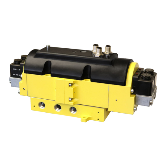
- Page 1 ROSS CONTROLS ® ™ CC4 s ross heCk eries ylinder ontrol and ouble alVes ntegration uide www.rosscontrols.com...
-
Page 2: Table Of Contents
Limitations of Load Holding Due to System Leakage Valve Test Procedure CC4 Validation Test Procedure for Valve Operation and External Monitoring Logic 10 - 14 Cautions, Warnings and Standard Warranty Cover Global Locations ROSS CONTROLS © 2019, ® . All Rights Reserved. -
Page 3: Introduction
Introduction ROSS Controls offers a variety of safety valves for use in various safety functions such as safe exhaust, safe cylinder return, and safe cylinder control/stop (load holding). This document focuses specifically on ROSS Controls’ 4/3 CC4 Series valves that are used for safe cylinder control/stop functions and utilize magnetic proximity sensors (PNP) to provide feedback to a safety control system for external monitoring. -
Page 4: Cc4 Wiring (Pinouts)
Once a fault is detected, the safety control system should turn off the outputs to all the valve solenoids. See Loss of Supply Pressure While Actuated on page 6. WARNING: A loss of supply pressure to the valve and cylinder could cause unexpected cylinder movement. ROSS CONTROLS © 2019, ® . All Rights Reserved. - Page 5 CC4 Series Valves Integration Guide In order to convert the CC4 valve to external pilot supply: A. Shut-off and exhaust all pressure from the system and disconnect all electrical power from the valve. B. Remove the cover from the valve (2 screws). See photo below (left). C.
-
Page 6: Operation & Monitoring Requirements For 4/3 Cc4 Series Valves
• Receipt of signals at solenoids not synchronous • Pilot valves experiencing a switching delay due to damaged components, dirt, debris or resinous oil • Excessive water build-up in the valve ROSS CONTROLS © 2019, ® . All Rights Reserved. -
Page 7: Feedback Monitoring (General)
CC4 Series Valves Integration Guide Feedback Monitoring (General) The CC4 valve is equipped with feedback proximity sensors that must be monitored by the user’s external safety control & monitoring system to detect fault conditions within the valve. Sensor feedback should always be opposite the solenoid actuating signals. In other words, when the solenoids are energized, the sensor outputs should be off and when the solenoids are de-energized, the sensor outputs should be on. -
Page 8: Actuation Fault Monitoring
Actuation Fault Monitoring logic. WARNING: Valve does not close due to loss of supply pressure until the supply pressure drops below 60 psig (4 bar) which could result in unexpected cylinder movement. ROSS CONTROLS © 2019, ® . All Rights Reserved. -
Page 9: No Supply Pressure Applied Before Actuation
CC4 Series Valves Integration Guide Operation & Monitoring – Loss of Supply Pressure While Actuated (continued) Using EXTERNAL Pilot Supply (Optional configuration): When operating the CC4 valve with EXTERNAL pilot pressure (supplied externally from a separate source through the X port), a loss of supply pressure in supply port 1, but not in external pilot supply port X, will allow the valves to remain actuated;... -
Page 10: Cc4 Validation Test Procedure For Valve Operation And External Monitoring Logic
None Pressure Stop Attempt to energize solenoids 12A & 12B Yes* Reconnect solenoid 12A De-energize solenoids 12A & 12B Reset the safety control system Fault should be detected within 150 msec. ROSS CONTROLS © 2019, ® . All Rights Reserved. - Page 11 All closed Stop Yes** Reconnect solenoid signal wire to solenoid 14A De-energize solenoids 14A & 14B Reset the safety control system Fault should be detected within 150 msec. Fault should occur immediately. ROSS CONTROLS © 2019, ® . All Rights Reserved.
- Page 12 Reconnect sensor output wire to sensor A Attempt to energize solenoids 12A & 12B De-energize solenoids 12A & 12B Reset the safety control system Fault should be detected within 150 msec. Fault should occur immediately. ROSS CONTROLS © 2019, ® . All Rights Reserved.
- Page 13 Energize solenoids 12A & 12B 1 to 2 | 4 to 3 Pressure None Retract De-energize solenoids 12A & 12B All closed Stop Fault should be detected within 150 msec. Fault should occur immediately. ROSS CONTROLS © 2019, ® . All Rights Reserved.
- Page 14 Reset the safety control system Energize solenoids 14A & 14B 1 to 4 | 2 to 3 None Pressure Extend De-energize solenoids 14A & 14B All closed Stop Fault should occur immediately. ROSS CONTROLS © 2019, ® . All Rights Reserved.
-
Page 15: Cautions, Warnings And Standard Warranty
CC4 Series Valves Integration Guide CAUTIONS, WARNINGS AND STANDARD WARRANTY ROSS OPERATING VALVE, ROSS CONTROLS , ROSS DECCO , and AUTOMATIC VALVE INDUSTRIAL, ® ® collectively the “ROSS Group". PRE-INSTALLATION or SERVICE point between 180°F (82°C) and 220°F (104°C), and an ISO 32, or lighter, viscosity. - Page 16 Japan Tel: 81-42-778-7251 www.rossasia.co.jp ROSS UK Ltd. Tel: 44-1543-671495 www.rossuk.co.uk ROSS SOUTH AMERICA Ltda. Brazil Tel: 55-11-4335-2200 www.rosscontrols.com.br ROSS CONTROLS INDIA Pvt. Ltd. India Tel: 91-44-2624-9040 www.rosscontrols.com ROSS CONTROLS (CHINA) Ltd. China Tel: 86-21-6915-7961 www.rosscontrolschina.com ROSS FRANCE S.A.S. France Tel: 33-1-49-45-65-65 www.rossfrance.com...
Need help?
Do you have a question about the CrossCheck CC4 Series and is the answer not in the manual?
Questions and answers