Vega VEGAFLEX 86 Operating Instructions Manual
Tdr sensor for continuous level and interface measurement of liquids
Hide thumbs
Also See for VEGAFLEX 86:
- Operating instructions manual (104 pages) ,
- Quick setup manual (20 pages) ,
- Operating instruction (92 pages)

Related Manuals for Vega VEGAFLEX 86


Summary of Contents for Vega VEGAFLEX 86
- Page 1 Operating Instructions TDR sensor for continuous level and interface measurement of liquids VEGAFLEX 86 Modbus and Levelmaster protocol Converter version in second chamber Coax probe -20 … +250 °C Document ID: 49475...
-
Page 2: Table Of Contents
Parameter adjustment with PACTware ................49 Set instrument address ....................50 Set up with the quick setup ..................... 51 Save parameter adjustment data..................53 Diagnosis, asset management and service ................ 54 Maintenance ........................54 VEGAFLEX 86 • Modbus and Levelmaster protocol... - Page 3 11.8 Industrial property rights ....................82 11.9 Trademark ........................82 Safety instructions for Ex areas: Take note of the Ex specific safety instructions for Ex applications. These instructions are attached as documents to each instrument with Ex approval and are part of the operating instructions. Editing status: 2023-05-23 VEGAFLEX 86 • Modbus and Levelmaster protocol...
-
Page 4: About This Document
Symbols used Document ID This symbol on the front page of this instruction refers to the Docu- ment ID. By entering the Document ID on www.vega.com you will reach the document download. Information, note, tip: This symbol indicates helpful additional infor- mation and tips for successful work. -
Page 5: For Your Safety
During work on and with the device, the required personal protective equipment must always be worn. Appropriate use VEGAFLEX 86 is a sensor for continuous level measurement. You can find detailed information about the area of application in chapter " Product description". Operational reliability is ensured only if the instrument is properly used according to the specifications in the operating instructions manual as well as possible supplementary instructions. -
Page 6: Namur Recommendations
That is why we have introduced an environment management system with the goal of continuously improving company environmental pro- tection. The environment management system is certified according to DIN EN ISO 14001. Please help us fulfil this obligation by observing the environmental instructions in this manual: • Chapter " Packaging, transport and storage" • Chapter " Disposal" VEGAFLEX 86 • Modbus and Levelmaster protocol... -
Page 7: Product Description
Scope of this operating This operating instructions manual applies to the following instrument instructions versions: • Hardware from 1.0.0 • Software from 1.3.0 • Only for instrument versions without SIL qualification Type label The type label contains the most important data for identification and use of the instrument: VEGAFLEX 86 • Modbus and Levelmaster protocol... - Page 8 Alternatively, you can access the data via your smartphone: • Download the VEGA Tools app from the " Apple App Store" or the " Google Play Store" • Scan the QR-code on the type label of the device or •...
-
Page 9: Principle Of Operation
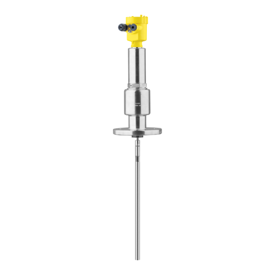
Sensor electronics Principle of operation Application area The VEGAFLEX 86 is a level sensor with coax probe for continuous level or interface measurement, suitable for applications in liquids with high temperatures up to 250 °C (482 °F). High frequency microwave pulses are guided along a steel cable or... - Page 10 Example: upper medium dielectric constant 2, lower medium at least dielectric constant 12. Gas phase (L3) • Air or gas mixture • Gas phase - dependent on the application, gas phase does not always exist (d2 = 0) VEGAFLEX 86 • Modbus and Levelmaster protocol...
-
Page 11: Packaging, Transport And Storage
The integrated Bluetooth module (optional) enables wireless adjust- ment via standard adjustment devices. VEGACONNECT The interface adapter VEGACONNECT enables the connection of communication-capable instruments to the USB interface of a PC. VEGAFLEX 86 • Modbus and Levelmaster protocol... - Page 12 3 Product description VEGADIS 81 The VEGADIS 81 is an external display and adjustment unit for VEGA plics sensors. ® VEGADIS adapter The VEGADIS adapter is an accessory part for sensors with double chamber housing. It enables the connection of VEGADIS 81 to the sensor housing via an M12 x 1 plug.
-
Page 13: Mounting
Note: Process conditions For safety reasons, the instrument must only be operated within the permissible process conditions. You can find detailed information on the process conditions in chapter " Technical data" of the operating instructions or on the type label. VEGAFLEX 86 • Modbus and Levelmaster protocol... -
Page 14: Mounting Instructions
Fig. 5: Vessel with conical bottom Welding work Before beginning the welding work, remove the electronics module from the sensor. By doing this, you avoid damage to the electronics through inductive coupling. Do not mount the instruments in or above the filling stream. Make sure Inflowing medium that you detect the medium surface, not the inflowing product. VEGAFLEX 86 • Modbus and Levelmaster protocol... - Page 15 In case of strong external vibrations or if there is a danger of the co- axial probe touching the vessel wall, then the probe must be fastened at the bottom end. Keep in mind that measurement is not possible below the fastening point. VEGAFLEX 86 • Modbus and Levelmaster protocol...
- Page 16 The spacer may be incorporated in the vessel insulation up to max. 50 mm (1.97 in). Only then is a reliable temperature decoupling guaranteed. Fig. 8: Mounting the instrument on insulated vessels. Temperature insulation Ambient temperature on the housing VEGAFLEX 86 • Modbus and Levelmaster protocol...
-
Page 17: Connecting To Power Supply And Bus System
In the case of instrument housings with self-sealing NPT threads, it is not possible to have the cable entries screwed in at the factory. The free openings for the cable glands are therefore covered with red dust protection caps as transport protection. VEGAFLEX 86 • Modbus and Levelmaster protocol... -
Page 18: Connecting
3. Remove approx. 10 cm (4 in) of the cable mantle (signal output), strip approx. 1 cm (0.4 in) insulation from the ends of the indi- vidual wires 4. Insert the cable into the sensor through the cable entry VEGAFLEX 86 • Modbus and Levelmaster protocol... - Page 19 The terminal blocks are pluggable and can be removed from the housing insert. To do this, lift the terminal block with a small screwdriv- er and pull it out. When inserting the terminal block again, you should hear it snap in. VEGAFLEX 86 • Modbus and Levelmaster protocol...
-
Page 20: Wiring Plan
Internal connection to the connection compartment For display and adjustment module or interface adapter Connection compartment MODBUS power supply off on Fig. 12: Connection compartment USB interface 2 Slide switch for integrated termination resistor (120 Ω) Modbus signal Voltage supply Terminal Function Polarity Voltage supply VEGAFLEX 86 • Modbus and Levelmaster protocol... -
Page 21: Double Chamber Housing With Vegadis-Adapter
Fig. 14: Top view of the M12 x 1 plug connector Pin 1 Pin 2 Pin 3 Pin 4 Contact pin Colour, connection ca- Terminal, electronics ble in the sensor module Pin 1 Brown Pin 2 White Pin 3 Blue Pin 4 Black VEGAFLEX 86 • Modbus and Levelmaster protocol... -
Page 22: Switch-On Phase
• Status byte goes to fault value Then the actual measured value is output to the signal cable. The value takes into account settings that have already been carried out, e.g. default setting. VEGAFLEX 86 • Modbus and Levelmaster protocol... -
Page 23: Set Up The Sensor With The Display And Adjustment Module
The display and adjustment module is powered by the sensor, an ad- ditional connection is not necessary. Fig. 15: Insertion of the display and adjustment module Note: If you intend to retrofit the instrument with a display and adjustment module for continuous measured value indication, a higher lid with an inspection glass is required. VEGAFLEX 86 • Modbus and Levelmaster protocol... -
Page 24: Adjustment System
The pen oper- ates the four keys of the display and adjustment module right through the closed lid (with inspection window) of the sensor housing. VEGAFLEX 86 • Modbus and Levelmaster protocol... - Page 25 [OK] will not be saved. Switch-on phase After switching on, the VEGAFLEX 86 carries out a short self-test where the device software is checked. The output signal transmits a fault signal during the switch-on phase. The following information is displayed on the display and adjustment module during the startup procedure: •...
-
Page 26: Parameter Adjustment - Quick Setup
Info: Instrument name, hardware and software version, date of manu- facture, instrument features Note: For optimum setting of the measuring point, the individual submenu items in the main menu item " Setup" should be selected one after VEGAFLEX 86 • Modbus and Levelmaster protocol... - Page 27 When choosing " Yes", then the probe length will be determined automatically. When choosing " No", you can enter the probe length manually. Application - Medium Coax probes can be only used in liquids. In this menu item, the fixed type adjusted medium type " Liquid" is displayed. VEGAFLEX 86 • Modbus and Levelmaster protocol...
- Page 28 " Application". In this menu item you can enter if there is a superimposed gas phase in your application. Only set the function to " Yes", if the gas phase is permanently pre- sent. VEGAFLEX 86 • Modbus and Levelmaster protocol...
- Page 29 In this menu item you can enter the min. adjustment for the level. With Min. adjustment level interface measurement this is the minimum total level. Adjust the requested percentage value with [+] and store with [OK]. VEGAFLEX 86 • Modbus and Levelmaster protocol...
- Page 30 Enter the respective distance value in m for the interface correspond- ing to the percentage value of the interface. Damping To damp process-dependent measured value fluctuations, set an integration time of 0 … 999 s in this menu item. VEGAFLEX 86 • Modbus and Levelmaster protocol...
- Page 31 For non-linear vessel forms, enter the vessel height and the socket correction. For the vessel height, you have to enter the total height of the vessel. For the nozzle correction you have to enter the height of the nozzle above the upper edge of the vessel. If the nozzle is lower than the up- per edge of the vessel, this value can also be negative. VEGAFLEX 86 • Modbus and Levelmaster protocol...
- Page 32 The default setting is min. current 3.8 mA and max. current 20.5 mA. False signal suppression The following circumstances cause interfering reflections and can influence the measurement: • High mounting nozzles • Vessel internals such as struts VEGAFLEX 86 • Modbus and Levelmaster protocol...
- Page 33 Lock/Unlock adjustment In the menu item " Lock/unlock adjustment", you can protect the sen- sor parameters against unauthorized or inadvertent modification. The PIN is activated/deactivated permanently. With active PIN, only the following adjustment functions are possible without entering a PIN: VEGAFLEX 86 • Modbus and Levelmaster protocol...
- Page 34 In delivery status, the sensor is set to English. Displayed value 1 In this menu item, you define the indication of the measured value on the display. You can display two different measured values. In this menu item, you define measured value 1. The default setting for the displayed value 1 is " Filling height Level". Displayed value 2 In this menu item, you define the indication of the measured value on the display. You can display two different measured values. In this menu item, you define measured value 2. VEGAFLEX 86 • Modbus and Levelmaster protocol...
- Page 35 If you have selected interface measurement under the menu item " Setup - Application", the peak values of the interface measurement are displayed in addition to the peak values of the level measurement. VEGAFLEX 86 • Modbus and Levelmaster protocol...
- Page 36 This menu item displays the peak values of the electronics tempera- ture as well as the dielectric constant. In another window you can carry out a reset of the two peak values separately. Information: If one of the display values flashes, there is actually no valid value available. VEGAFLEX 86 • Modbus and Levelmaster protocol...
- Page 37 With this, you can detect signal changes over the operating time. With the adjustment software PACTware and the PC, the high-resolution echo curve can be displayed and used to compare the echo curve of the setup with the actual echo curve. VEGAFLEX 86 • Modbus and Levelmaster protocol...
- Page 38 Basic settings: Restores the parameter settings, incl. special param- eters, to the default values of the respective instrument. Any stored VEGAFLEX 86 • Modbus and Levelmaster protocol...
- Page 39 Scaling unit - Level Litres Scaling format - Level Without decimal positions Scaling level - 100 % corresponds to Scaling level - 0 % corresponds to Scaling variable - Interface Volume Scaling unit - Interface Litres VEGAFLEX 86 • Modbus and Levelmaster protocol...
- Page 40 The following data or settings for adjustment of the display and ad- justment module are saved: • All data of the menu " Setup" and " Display" • In the menu " Additional adjustments" the items " Reset, Date/ Time" • Special parameters VEGAFLEX 86 • Modbus and Levelmaster protocol...
- Page 41 Scaling level - Scaling format In menu item " Scaling format" you define the scaling format on the display and the scaling of the measured level value for 0 % and 100 %. VEGAFLEX 86 • Modbus and Levelmaster protocol...
- Page 42 In menu item " Current output, variable" you specify which measured output size variable the current output refers to. In menu item " Current output, adjustment" you can assign a respec- Current output - Current output adjustment tive measured value to the current output. VEGAFLEX 86 • Modbus and Levelmaster protocol...
- Page 43 6.5.5 Info Device name In this menu, you read out the instrument name and the instrument serial number. Instrument version In this menu item, the hardware and software version of the sensor is displayed. VEGAFLEX 86 • Modbus and Levelmaster protocol...
-
Page 44: Save Parameter Adjustment Data
In the display and adjust- If the instrument is equipped with a display and adjustment module, ment module the parameter adjustment data can be saved therein. The procedure is described in menu item " Copy device settings". VEGAFLEX 86 • Modbus and Levelmaster protocol... -
Page 45: Set Up With Smartphone/Tablet/Pc/Notebook Via Bluetooth
PIN in the adjustment menu of the respective sensor, e.g. to " 1111". Use " OK" to switch to the input menu. Basic adjustment Display Diagnostics Service Info Deactivate permanently? VEGAFLEX 86 • Modbus and Levelmaster protocol... -
Page 46: Connecting
PC/Notebook Start PACTware and the VEGA project assistant. Select the device search via Bluetooth and start the search function. The device auto- matically searches for Bluetooth-capable devices in the vicinity. VEGAFLEX 86 • Modbus and Levelmaster protocol... -
Page 47: Sensor Parameter Adjustment
After successful authentication, the next con- nection functions without authentication. For authentication, enter in the next menu window the 4-digit sensor PIN. Sensor parameter adjustment The sensor parameterization is carried out via the adjustment app on the smartphone/tablet or the DTM on the PC/notebook. App view Fig. 20: Example of an app view - Setup sensor adjustment VEGAFLEX 86 • Modbus and Levelmaster protocol... -
Page 48: Setting Up Sensor And Modbus Interface With Pactware
Scope of the parameter adjustment: • Sensor electronics • Modbus electronics Fig. 22: Connecting the PC via USB to the Modbus electronics 1 USB cable to the PC To the RS 485 cable Connection of the PC to the RS 485 cable is carried out via a stand- ard interface adapter RS 485/USB. VEGAFLEX 86 • Modbus and Levelmaster protocol... -
Page 49: Parameter Adjustment With Pactware
Further setup steps are described in the operating instructions manu- al " DTM Collection/PACTware" attached to each DTM Collection and which can also be downloaded from the Internet. Detailed descrip- tions are available in the online help of PACTware and the DTMs. VEGAFLEX 86 • Modbus and Levelmaster protocol... -
Page 50: Set Instrument Address
" Software". The full version is avail- able on CD from the agency serving you. Set instrument address The VEGAFLEX 86 requires an address for participating as a sensor in the Modbus communication. The addess setting is carried out via a PC with PACTware/DTM or Modbus RTU. -
Page 51: Set Up With The Quick Setup
The quick setup is another option for parameter adjustment of the sensor. It allows fast, convenient adjustment of the most important parameters to adapt the sensor quickly to standard applications. To use it, select the function " Quick setup" in the start screen. VEGAFLEX 86 • Modbus and Levelmaster protocol... - Page 52 2 Extended adjustment Maintenance Quick setup With quick setup you can carry out the parameter adjustment of VEGAFLEX 86 for your application in just a few simple steps. The assistant-driven adjustment includes the basic settings for simple, reliable setup and commissioning. Information: If the function is inactive, then possibly no instrument is connected.
-
Page 53: Save Parameter Adjustment Data
8 Setting up sensor and Modbus interface with PACTware Save parameter adjustment data We recommend documenting or saving the parameterisation data via PACTware. That way the data are available for multiple use or service purposes. VEGAFLEX 86 • Modbus and Levelmaster protocol... -
Page 54: Diagnosis, Asset Management And Service
Up to 500 events are automatically stored with a time stamp in the sensor (non-deletable). Each entry contains date/time, event type, event description and value. Event types are for example: • Modification of a parameter • Switch-on and switch-off times • Status messages (according to NE 107) • Error messages (according to NE 107) The data are read out via a PC with PACTware/DTM or the control system with EDD. VEGAFLEX 86 • Modbus and Levelmaster protocol... -
Page 55: Asset Management Function
This status message is always active. It cannot be deactivated by the user. Function check: The instrument is being worked on, the measured value is temporarily invalid (for example during simulation). This status message is inactive by default. VEGAFLEX 86 • Modbus and Levelmaster protocol... - Page 56 Duration up to approx. 3 minutes depending on the version and pa- rameter settings F113 Error in the internal instrument com- Disconnect operating voltage briefly munication Communication Send instrument for repair error VEGAFLEX 86 • Modbus and Levelmaster protocol...
- Page 57 State in CMD 48 S600 Temperature of the processing elec- Check ambient temperature Bit 8 of tronics in the non-specified section Byte 14 … 24 Impermissible Insulate electronics electronics tem- Use instrument with higher temper- perature ature range VEGAFLEX 86 • Modbus and Levelmaster protocol...
-
Page 58: Rectify Faults
Error when carrying out a reset strument settings False signal suppression faulty Tab. 10: Error codes and text messages, information on causes as well as corrective measures Rectify faults Reaction when malfunc- The operator of the system is responsible for taking suitable meas- tion occurs ures to rectify faults. VEGAFLEX 86 • Modbus and Levelmaster protocol... - Page 59 If the output level is constant, the cause could also be the fault setting of the output to " Hold value". If the level is too low, the reason could be a line resistance that is too high VEGAFLEX 86 • Modbus and Levelmaster protocol...
- Page 60 Eliminate false signals in the close range ≥ 100 % or 0 m distance close range due to false signals in the Check installation conditions close range. The sensor goes into over- If possible, switch off the function "Over- fill protection mode. The max. level (0 m fill protection" distance) as well as the status message "Overfill protection" are output. time VEGAFLEX 86 • Modbus and Levelmaster protocol...
-
Page 61: Exchanging The Electronics Module
24 hour service hotline Should these measures not be successful, please call in urgent cases the VEGA service hotline under the phone no. +49 1805 858550. The hotline is also available outside normal working hours, seven days a week around the clock. -
Page 62: Software Update
• Attach the completed form and, if need be, also a safety data sheet outside on the packaging • Ask the agency serving you to get the address for the return ship- ment. You can find the agency on our homepage. VEGAFLEX 86 • Modbus and Levelmaster protocol... -
Page 63: Dismount
If personal data is stored on the old device to be disposed of, delete it before disposal. If you have no way to dispose of the old instrument properly, please contact us concerning return and disposal. VEGAFLEX 86 • Modbus and Levelmaster protocol... -
Page 64: Supplement
< 10 mbar l/s Not suitable for hot steam applications > 150 °C (> 302 °F). In this case, use a device with a ceramic-graphite seal. Aluminium, stainless steel precision casting and Ex d housing VEGAFLEX 86 • Modbus and Levelmaster protocol... - Page 65 Ʋ Vessel metallic, ø 1 m (3.281 ft), centric mounting, process fit- ting flush with the vessel ceiling Ʋ Medium Water/Oil (dielectric constant ~2.0) Ʋ Mounting Probe end does not touch the vessel bottom Sensor parameter adjustment No gating out of false signals carried out With interface measurement = 2.0 VEGAFLEX 86 • Modbus and Levelmaster protocol...
- Page 66 Typical deviation - Interface measure- ± 5 mm (0.197 in) ment Typical deviation - Total level interface See following diagrams measurement Typical deviation - Level measurement See following diagrams 4)5) Depending on the mounting conditions, deviations can occur which can be rectified by adapting the adjustment or changing the measured value offset in the DTM service mode The blocking distances can be optimized via a false signal suppression. VEGAFLEX 86 • Modbus and Levelmaster protocol...
- Page 67 -2 mm (-0.079 ") -10 mm (-0.394 ") 0,1 m 0,1 m (3.937 0,25 m (9.842 " " (3.937 ") 0,05 m (1.968 ") Fig. 31: Deviation VEGAFLEX 86 in coax version in oil (measurement length up to 1.5 m/4.92 ft) Blocking distance (no measurement possible in this area) Probe length VEGAFLEX 86 • Modbus and Levelmaster protocol...
- Page 68 -0.02 % 0.03 % 0.25 % Steam (saturated 100 °C (212 °F) 0.26 % steam) 150 °C (302 °F) 0.17 % 2.1 % Characteristics and performance data Measuring cycle time < 500 ms VEGAFLEX 86 • Modbus and Levelmaster protocol...
- Page 69 Aluminium housing Plastic housing Stainless steel housing (precision casting) Stainless steel housing (electropolished) Time span after a sudden measuring distance change by max. 0.5 m in liquid applications, max 2 m with bulk solids applications, until the output signal has taken for the first time 90 % of the final value (IEC 61298-2). VEGAFLEX 86 • Modbus and Levelmaster protocol...
- Page 70 -40 … +85 °C (-40 … +185 °F) Resolution < 0.1 K Deviation ± 3 K Availability of the temperature values Ʋ Indication Via the display and adjustment module Ʋ Output Via the respective output signal VEGAFLEX 86 • Modbus and Levelmaster protocol...
-
Page 71: Device Communication Modbus
Pollution degree Protection rating (IEC 61010-1) 11.2 Device communication Modbus In the following, the necessary device-specific details are shown. You can find further information of Modbus on www.modbus.org. Parameters for the bus communication The VEGAFLEX 86 is preset with the following default values: Parameter Configurable Values Default Value Baud Rate 1200, 2400, 4800, 9600, 19200... -
Page 72: Modbus Register
11 Supplement Code". Hence the RTU knows the registers of the VEGAFLEX 86 which must be contacted for the variables and status information. Format Code Byte transmission order ABCD CDAB DCBA BADC 11.3 Modbus register Holding Register The Holding registers consist of 16 bit. They can be read and written. Before each command, the address (1 byte), after each command, a CRC (2 byte) is sent. - Page 73 DWord Third Variable in Byte Order BACD (Middle Endian) 2208 DWord Quarternary Variable in Byte Order BACD (Middle Endian) Unit Codes for Register 104, 108, 112, 116 Unit Code Measurement Unit Degree Celsius VEGAFLEX 86 • Modbus and Levelmaster protocol...
-
Page 74: Modbus Rtu Commands
1 Byte 0x04 Start Address 2 Bytes 0x0000 to 0xFFFF Number of Registers N*2 Bytes 1 to 127 (0x7D) Response: Function Code 1 Byte 0x04 Byte Count 2 Bytes Register Value N*2 Bytes Data VEGAFLEX 86 • Modbus and Levelmaster protocol... - Page 75 0x0001 to 0x007B Byte Count 1 Byte Register Value N*2 Bytes Data Response: Function Code 1 Byte 0x10 Start Address 2 Bytes 0x0000 to 0xFFFF Number of Registers 2 Bytes 0x01 to 0x7B VEGAFLEX 86 • Modbus and Levelmaster protocol...
-
Page 76: Levelmaster Commands
List of Object value 1 Byte Depending on the Object ID 11.5 Levelmaster commands The VEGAFLEX 86 is also suitable for connection to the following RTUs with Levelmaster protocol. The Levelmaster protocol is often called " Siemens" " Tank protocol". Protocol ABB Totalflow... - Page 77 If the temperature should be transmitted in the Levelmaster protocol, then TV must be set in the sensor to temperature. PV, SV and TV can be adjusted via the sensor DTM. Report Unit Number Parameter Length Code/Data Request: Report Unit Number 5 characters ASCII U**N? VEGAFLEX 86 • Modbus and Levelmaster protocol...
- Page 78 = milliseconds (50 up to 250), default = 127 ms Response: Set Receive to Transmit 6 characters ASCII UuuROK Delay Report Number of Floats Parameter Length Code/Data Request: Report Number of Floats 4 characters ASCII UuuF VEGAFLEX 86 • Modbus and Levelmaster protocol...
-
Page 79: Configuration Of Typical Modbus Hosts
Parameters for Modbus Hosts Parameter Value Fisher Value ABB Total Value Fisher Value Fisher Value Scada- ROC 809 Flow Thermo Elec- Bristol Control- Pack tron Autopilot Wave Micro Baud Rate 9600 9600 9600 9600 9600 VEGAFLEX 86 • Modbus and Levelmaster protocol... -
Page 80: Dimensions
ScadaPack - Register address for 1302 is address 31303 11.7 Dimensions The following dimensional drawings represent only an extract of all possible versions. Detailed dimensional drawings can be downloaded at www.vega.com/downloads under " Drawings". Housing ~ 87 mm ~ 84 mm (3.43") - Page 81 11 Supplement VEGAFLEX 86, coax version (-20 … +250 °C/-4 … +482 °F) SW 41 mm ø 21,3 mm (0.84") Fig. 36: VEGAFLEX 86, coax version with thread (-20 … +250 °C/-4 … +482 °F) Sensor length, see chapter " Technical data" Max. height of the vessel insulation VEGAFLEX 86 • Modbus and Levelmaster protocol...
-
Page 82: Industrial Property Rights
Les lignes de produits VEGA sont globalement protégées par des droits de propriété intellec- tuelle. Pour plus d'informations, on pourra se référer au site www.vega.com. VEGA lineas de productos están protegidas por los derechos en el campo de la propiedad indus- trial. Para mayor información revise la pagina web www.vega.com. - Page 83 Factory calibration date 44 Sensor characteristics 44 False signal suppression 32 Fault rectification 59 Service hotline 61 Simulation 37 Functional principle 9 Special parameters 43 Gas phase 28 Type label 7 Type of medium 27 HART address 43 VEGAFLEX 86 • Modbus and Levelmaster protocol...
- Page 84 INDEX Units 27 Vessel insulation 16 VEGAFLEX 86 • Modbus and Levelmaster protocol...
- Page 85 Notes VEGAFLEX 86 • Modbus and Levelmaster protocol...
- Page 86 Notes VEGAFLEX 86 • Modbus and Levelmaster protocol...
- Page 87 Notes VEGAFLEX 86 • Modbus and Levelmaster protocol...
- Page 88 Subject to change without prior notice © VEGA Grieshaber KG, Schiltach/Germany 2023 VEGA Grieshaber KG Am Hohenstein 113 Phone +49 7836 50-0 77761 Schiltach E-mail: info.de@vega.com...
Need help?
Do you have a question about the VEGAFLEX 86 and is the answer not in the manual?
Questions and answers