Vega VEGAFLEX 86 Operating Instructions Manual
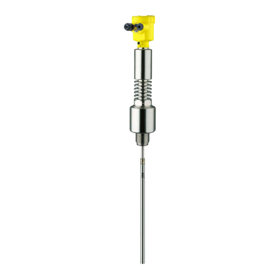
Tdr sensor for continuous level and interface measurement of liquids
Hide thumbs
Also See for VEGAFLEX 86:
- Operating instructions manual (101 pages) ,
- Quick setup manual (20 pages) ,
- Operating instruction (92 pages)
Table of Contents

Related Manuals for Vega VEGAFLEX 86


Summary of Contents for Vega VEGAFLEX 86
- Page 1 Operating Instructions TDR sensor for continuous level and interface measurement of liquids VEGAFLEX 86 Two-wire 4 … 20 mA/HART Rod and cable probe With SIL qualification -196 … +280 °C -196 … +450 °C Document ID: 44234...
-
Page 2: Table Of Contents
Insert display and adjustment module ................39 Adjustment system ......................40 Parameter adjustment - Extended adjustment..............41 Saving the parameterisation data ................... 61 Setup with PACTware ......................63 Connect the PC ......................63 VEGAFLEX 86 • Two-wire 4 … 20 mA/HART... - Page 3 12.4 Trademark ........................99 Safety instructions for Ex areas Take note of the Ex specific safety instructions for Ex applications. These instructions are attached as documents to each instrument with Ex approval and are part of the operating instructions. Editing status: 2020-01-24 VEGAFLEX 86 • Two-wire 4 … 20 mA/HART...
-
Page 4: About This Document
Symbols used Document ID This symbol on the front page of this instruction refers to the Docu- ment ID. By entering the Document ID on www.vega.com you will reach the document download. Information, note, tip: This symbol indicates helpful additional infor- mation and tips for successful work. -
Page 5: For Your Safety
During work on and with the device, the required personal protective equipment must always be worn. Appropriate use VEGAFLEX 86 is a sensor for continuous level measurement. You can find detailed information about the area of application in chapter "Product description". Operational reliability is ensured only if the instrument is properly used according to the specifications in the operating instructions manual as well as possible supplementary instructions. -
Page 6: Eu Conformity
This information is only valid for USA and Canada. Hence the follow- ing text is only available in the English language. Installations in the US shall comply with the relevant requirements of the National Electrical Code (ANSI/NFPA 70). VEGAFLEX 86 • Two-wire 4 … 20 mA/HART... -
Page 7: Environmental Instructions
That is why we have introduced an environment management system with the goal of continuously improving company environmental pro- tection. The environment management system is certified according to DIN EN ISO 14001. Please help us fulfil this obligation by observing the environmental instructions in this manual: • Chapter "Packaging, transport and storage" • Chapter "Disposal" VEGAFLEX 86 • Two-wire 4 … 20 mA/HART... -
Page 8: Product Description
Scope of this operating This operating instructions manual applies to the following instrument instructions versions: • Hardware from 1.0.0 • Software from 1.2.0 • DTM from version 1.67.2 Type label The type label contains the most important data for identification and use of the instrument: VEGAFLEX 86 • Two-wire 4 … 20 mA/HART... - Page 9 Alternatively, you can access the data via your smartphone: • Download the VEGA Tools app from the "Apple App Store" or the "Google Play Store" • Scan the DataMatrix code on the type label of the instrument or •...
-
Page 10: Principle Of Operation
3 Product description Principle of operation Application area The VEGAFLEX 86 is a level sensor with cable or rod probe for continuous level or interface measurement, particularly suitable for applications in high temperatures up to +450 °C (842 °F). Due to the qualification up to SIL2 or homogeneous redundant up to SIL3 (IEC 61508) the VEGAFLEX 86 is suitable for the use in safety- instrumented systems (SIS). - Page 11 Example: upper medium dielectric constant 2, lower medium at least dielectric constant 12. Gas phase (L3) • Air or gas mixture • Gas phase - dependent on the application, gas phase does not always exist (d2 = 0) VEGAFLEX 86 • Two-wire 4 … 20 mA/HART...
-
Page 12: Packaging, Transport And Storage
The integrated Bluetooth module (optional) enables wireless adjust- ment via standard adjustment devices. VEGACONNECT The interface adapter VEGACONNECT enables the connection of communication-capable instruments to the USB interface of a PC. VEGAFLEX 86 • Two-wire 4 … 20 mA/HART... - Page 13 Rod/cable segments: 20 … 5900 mm (0.79 … 232 in) • Curved segments: 100 x 100 mm (3.94 … 3.94 in) The combination of a bypass tube and a VEGAFLEX 86 enables con- Bypass pipe tinuous level measurement outside the vessel. The bypass consists of a standpipe which is mounted as a communicating container on the side of the vessel via two process fittings. This kind of mounting...
- Page 14 3 Product description If you mount the VEGAFLEX 86 in a bypass tube or standpipe, you Centering have to avoid contact to the bypass tube by using a spacer at the probe end. Fixing facility If there is a risk of the cable probe touching the vessel wall during operation due to product movements or agitators, etc., the measuring...
-
Page 15: Mounting
Prior to setup you have to replace these protective caps with ap- proved cable glands or close the openings with suitable blind plugs. Note: Process conditions For safety reasons, the instrument must only be operated within the permissible process conditions. You can find detailed information on VEGAFLEX 86 • Two-wire 4 … 20 mA/HART... -
Page 16: Mounting Instructions
Mounting instructions Installation position Mount VEGAFLEX 86 in such a way that the distance to vessel instal- lations or to the vessel wall is at least 300 mm (12 in). In non-metallic vessels, the distance to the vessel wall should be at least 500 mm (19.7 in). - Page 17 Higher sockets or sockets with a bigger diameter can generally be used. They can, however, increase the upper dead zone. Check if this is relevant for your measurement. In such cases, always carry out a false signal suppression after mounting. You can find further information under "Setup procedure". VEGAFLEX 86 • Two-wire 4 … 20 mA/HART...
- Page 18 Unfavourable mounting 2 Socket flush - optimum mounting Welding work Before beginning the welding work, remove the electronics module from the sensor. By doing this, you avoid damage to the electronics through inductive coupling. Inflowing medium Do not mount the instruments in or above the filling stream. Make sure that you detect the product surface, not the inflowing product. VEGAFLEX 86 • Two-wire 4 … 20 mA/HART...
- Page 19 You can thus measure the complete range of the medium in the bypass tube (h). When designing the bypass tube, keep the dead zone of the probe in mind and select the length of the bypass tube above the upper lateral filling opening accordingly. VEGAFLEX 86 • Two-wire 4 … 20 mA/HART...
- Page 20 If durability is no problem, we recommend the use of uncoated metal standpipes. When the VEGAFLEX 86 is used in bypass tubes, contact with the tube wall must be avoided. We recommend for this purpose a cable probe with centering weight.
- Page 21 If durability is no problem, we recommend the use of uncoated metal standpipes. When the VEGAFLEX 86 is used in standpipes, contact with the tube wall must be avoided. We recommend for this purpose a cable probe with centering weight.
- Page 22 Instructions for the measurement: • The 100 % point with standpipes should be below the upper ventilation hole. • The 0 % point in standpipes should be above the gravity or center- ing weight. VEGAFLEX 86 • Two-wire 4 … 20 mA/HART...
- Page 23 Avoid undefined vessel connections, i.e. the connection must be either grounded reliably or isolated reliably. Any undefined change of this condition can lead to measurement errors. If there is a danger of the rod probe touching the vessel wall, fasten the probe at the bottom end. VEGAFLEX 86 • Two-wire 4 … 20 mA/HART...
- Page 24 To compensate for the resulting changes in signal runtime, let the instrument determine the probe length automatically. The determined probe length can deviate from the actual probe length when using curved or angled segments. VEGAFLEX 86 • Two-wire 4 … 20 mA/HART...
- Page 25 To compensate for the resulting changes in signal runtime, let the instrument determine the probe length automatically. You can find further information in the supplementary instructions of the rod and cable components. VEGAFLEX 86 • Two-wire 4 … 20 mA/HART...
-
Page 26: Connecting To Power Supply
In the case of instrument housings with self-sealing NPT threads, it is not possible to have the cable entries screwed in at the factory. The free openings for the cable glands are therefore covered with red dust protection caps as transport protection. VEGAFLEX 86 • Two-wire 4 … 20 mA/HART... -
Page 27: Connecting
4. Remove approx. 10 cm (4 in) of the cable mantle, strip approx. 1 cm (0.4 in) of insulation from the ends of the individual wires 5. Insert the cable into the sensor through the cable entry VEGAFLEX 86 • Two-wire 4 … 20 mA/HART... -
Page 28: Wiring Plan, Single Chamber Housing
10. Reinsert the display and adjustment module, if one was installed 11. Screw the housing lid back on The electrical connection is finished. Wiring plan, single chamber housing The following illustration applies to the non-Ex, Ex-ia and Ex-d ver- sion. VEGAFLEX 86 • Two-wire 4 … 20 mA/HART... -
Page 29: Wiring Plan, Double Chamber Housing
The following illustration applies to the non-Ex, Ex-ia and Ex-d ver- sion. Electronics compartment 4...20mA 6 7 8 Fig. 16: Electronics compartment - double chamber housing Internal connection to the connection compartment For display and adjustment module or interface adapter VEGAFLEX 86 • Two-wire 4 … 20 mA/HART... -
Page 30: Wiring Plan, Ex-D-Ia Double Chamber Housing
6 7 8 Fig. 18: Electronics compartment - double chamber housing Internal connection to the connection compartment For display and adjustment module or interface adapter Internal connection to the plug connector for external display and adjust- ment unit (optional) VEGAFLEX 86 • Two-wire 4 … 20 mA/HART... -
Page 31: Double Chamber Housing With Vegadis-Adapter
1 VEGADIS adapter Internal plug connection M12 x 1 plug connector Assignment of the plug connector Fig. 21: View to the plug connector M12 x 1 Pin 1 Pin 2 Pin 3 Pin 4 VEGAFLEX 86 • Two-wire 4 … 20 mA/HART... -
Page 32: Wiring Plan - Version Ip66/Ip68, 1 Bar
- additional current output 1 Current output (I) - Voltage supply of the sensor and signal output (with HART) Additional current output (II) - Voltage supply and signal output (without HART) Ground terminal for connection of the cable screening Switch-on phase After connection of the device to power supply, the device first carries out a self-test: VEGAFLEX 86 • Two-wire 4 … 20 mA/HART... - Page 33 PC • The output signal jumps briefly to the set fault current Then the actual measured value is output to the signal cable. The value takes into account settings that have already been carried out, e.g. default setting. VEGAFLEX 86 • Two-wire 4 … 20 mA/HART...
-
Page 34: Functional Safety (Sil)
SIL rating and can be also found on our homepage via the search. Application area The instrument can be used for point level detection or level measure- ment of liquids and bulk solids in safety-instrumented systems (SIS) VEGAFLEX 86 • Two-wire 4 … 20 mA/HART... -
Page 35: Safety Concept Of The Parameterization
The DTM suitable for the controller in conjunction with an adjust- ment software according to the FDT/DTM standard, e. g. PACT- ware Note: For operation of the VEGAFLEX 86 an actual DTM Collection is re- quired. The modification of safety-relevant parameters is only possible with active connection to the instrument (online mode). Safe parameterization... -
Page 36: Setup Process
Setup - Function test When locking the adjustment, the instrument checks the data of the measurement loop and decides on the basis of the evaluation results if a function test is required. VEGAFLEX 86 • Two-wire 4 … 20 mA/HART... - Page 37 If you have to interrupt the function, you can leave the VEGAFLEX 86 in the respective situation. As long as VEGAFLEX 86 is powered, the display and adjustment module remains in the currently set adjustment menu.
- Page 38 Then you carry out a comparison of two character strings. You must confirm that the character strings are identical. This is used to check the character presentation. Then you confirm that the serial number of your instrument has been carried over correctly. This is used to check device communication. Then, all modified parameters that have to be confirmed are listed. After this process is terminated, the safety function is again ensured. VEGAFLEX 86 • Two-wire 4 … 20 mA/HART...
-
Page 39: Set Up With The Display And Adjustment Module
The display and adjustment module is powered by the sensor, an ad- ditional connection is not necessary. Fig. 24: Installing the display and adjustment module in the electronics compart- ment of the single chamber housing VEGAFLEX 86 • Two-wire 4 … 20 mA/HART... -
Page 40: Adjustment System
– Confirm selected menu – Edit parameter – Save value • [->] key: – Change measured value presentation – Select list entry – Select editing position • [+] key: – Change value of the parameter VEGAFLEX 86 • Two-wire 4 … 20 mA/HART... -
Page 41: Parameter Adjustment - Extended Adjustment
[OK] will not be saved. Switch-on phase After switching on, the VEGAFLEX 86 carries out a short self-test where the device software is checked. The output signal transmits a fault signal during the switch-on phase. The following information is displayed on the display and adjustment module during the startup procedure: •... - Page 42 Capital letters from A … Z • Numbers from 0 … 9 • Special characters + - / _ blanks Units In this menu item you select the distance unit and the temperature unit. VEGAFLEX 86 • Two-wire 4 … 20 mA/HART...
- Page 43 (SIL). Application - Medium, In this menu item, you can define the type of medium (product). dielectric constant This menu item is only available if you have selected level measure- ment under the menu item "Application". VEGAFLEX 86 • Two-wire 4 … 20 mA/HART...
- Page 44 In this menu item you can enter the max. adjustment for the level. With interface measurement this is the maximum total level. Adjust the requested percentage value with [+] and store with [OK]. VEGAFLEX 86 • Two-wire 4 … 20 mA/HART...
- Page 45 As an alternative, you have the possibility taking over the adjustment of the level measurement also for the interface. Enter the respective distance value in m for the surface of the upper medium corresponding to the percentage value. VEGAFLEX 86 • Two-wire 4 … 20 mA/HART...
- Page 46 In the following, you have to enter the values for your vessel, for example the vessel height and the socket correction. VEGAFLEX 86 • Two-wire 4 … 20 mA/HART...
- Page 47 Current output, min./max. In the menu item "Current output Min./Max.", you determine the reac- tion of the current output during operation. The default setting is min. current 3.8 mA and max. current 20.5 mA. VEGAFLEX 86 • Two-wire 4 … 20 mA/HART...
- Page 48 The menu item "Delete" is used to completely delete an already cre- ated false signal suppression. This is useful if the saved false signal suppression no longer matches the metrological conditions in the vessel. VEGAFLEX 86 • Two-wire 4 … 20 mA/HART...
- Page 49 You can find the detailed sequence of the function test in chapter "Functional safety (SIL)" For this purpose, you should know the filling height of the vessel as well as the min. and max. levels respectively for 4 and 20 mA. You then can calculate the respective output current. VEGAFLEX 86 • Two-wire 4 … 20 mA/HART...
- Page 50 This deviation depends on the the accuracy requirements of your measurement loop. Determine the permissible tolerance for the deviation. If you have to interrupt the function, you can leave the VEGAFLEX 86 in the respective situation. As long as VEGAFLEX 86 is powered, the display and adjustment module remains in the currently set adjustment menu.
- Page 51 The default setting for the displayed value 1 is "Filling height Level". In this menu item, you define the indication of the measured value Displayed value 2 on the display. You can display two different measured values. In this menu item, you define measured value 2. The default setting for the displayed value 2 is the electronics tem- perature. Display format In this menu item, you define the display format of the measured value on the display. You can define different display formats for the two measured values. VEGAFLEX 86 • Two-wire 4 … 20 mA/HART...
- Page 52 In another window you can carry out a reset of the two peak values separately. Peak values, measure- The respective min. and max. measured values are saved in the ment reliability sensor. The two values are displayed in the menu item "Peak values, measurement reliability". VEGAFLEX 86 • Two-wire 4 … 20 mA/HART...
- Page 53 V. The signal strength enables an evalua- tion of the quality of the measurement. With the following functions you can zoom part sections of the echo curve. • "X-Zoom": Zoom function for the meas. distance • "Y-Zoom": 1, 2, 5 and 10x signal magnification in "V" VEGAFLEX 86 • Two-wire 4 … 20 mA/HART...
- Page 54 Under the sub-menu item "Echo curve memory" you can store the current echo curve. Parameter settings for recording the echo curve and the settings of the echo curve itself can be carried out in the adjustment software PACTware. VEGAFLEX 86 • Two-wire 4 … 20 mA/HART...
- Page 55 Basic settings: Resetting of the parameter settings incl. special parameters to the default values (presettings) of the respective instru- VEGAFLEX 86 • Two-wire 4 … 20 mA/HART...
- Page 56 Scaling variable - Level Volume in l Scaling unit - Level Litres Scaling format - Level Without decimal positions Scaling level - 100 % corresponds to Scaling level - 0 % corresponds to VEGAFLEX 86 • Two-wire 4 … 20 mA/HART...
- Page 57 Device memory - Echo curve memory Stopped Device memory - Measured value memory Started Device memory - Measured value memory - Measured values Distance level, percentage value level, reliabil- ity level, electronics temperature VEGAFLEX 86 • Two-wire 4 … 20 mA/HART...
- Page 58 The following requirements must be met for a successful transmis- sion: • The data can only be transferred to the same device type, e.g. VEGAFLEX 86 • It must be the same probe type, e.g. rod probe • The firmware of both devices is identical VEGAFLEX 86 • Two-wire 4 … 20 mA/HART...
- Page 59 0 % and 100 %. Scaling interface Since scaling is very extensive, scaling of the interface value was divided into two menu items. VEGAFLEX 86 • Two-wire 4 … 20 mA/HART...
- Page 60 In this menu item you can select the type and size of your probe from a list of all possible probes. This is necessary to adapt the electronics optimally to the probe. HART mode The sensor is permanently set to the HART mode "Analogue current output". This parameter cannot be modified. VEGAFLEX 86 • Two-wire 4 … 20 mA/HART...
-
Page 61: Saving The Parameterisation Data
Saving the parameterisation data On paper We recommended writing down the adjustment data, e.g. in this op- erating instructions manual, and archiving them afterwards. They are thus available for multiple use or service purposes. VEGAFLEX 86 • Two-wire 4 … 20 mA/HART... - Page 62 If the instrument is equipped with a display and adjustment module, In the display and adjust- ment module the parameter adjustment data can be saved therein. The procedure is described in menu item "Copy device settings". VEGAFLEX 86 • Two-wire 4 … 20 mA/HART...
-
Page 63: Setup With Pactware
Note: With power supply units with integrated HART resistance (internal resistance approx. 250 Ω), an additional external resistance is not necessary. This applies, e.g. to the VEGA instruments VEGATRENN 149A, VEGAMET 381, VEGAMET 391. Common Ex separators are also usually equipped with a sufficient current limiting resistance. In such cases, the interface converter can be connected parallel to the 4 …... - Page 64 In addition, there is a tank calculation program as well as a multiviewer for display and analysis of the saved measured value and echo curves. VEGAFLEX 86 • Two-wire 4 … 20 mA/HART...
-
Page 65: Saving The Parameterisation Data
CD from the agency serving you. Saving the parameterisation data We recommend documenting or saving the parameterisation data via PACTware. That way the data are available for multiple use or service purposes. VEGAFLEX 86 • Two-wire 4 … 20 mA/HART... -
Page 66: Set Up With Other Systems
This software is updated via the Internet and new EDDs are automatically accepted into the device catalogue of this software after they are released by the manufacturer. They can then be transferred to a Field Communicator. VEGAFLEX 86 • Two-wire 4 … 20 mA/HART... -
Page 67: Diagnostics And Servicing
Event memory Up to 500 events are automatically stored with a time stamp in the sensor (non-deletable). Each entry contains date/time, event type, event description and value. Event types are for example: VEGAFLEX 86 • Two-wire 4 … 20 mA/HART... -
Page 68: Status Messages
Fig. 31: Pictographs of the status messages Failure - red 2 Out of specification - yellow Function check - orange Maintenance - blue Failure: Due to a malfunction in the instrument, a fault message is output. VEGAFLEX 86 • Two-wire 4 … 20 mA/HART... - Page 69 Bit 6 of phase, the measured value could phase Byte 0 … 5 Measured value not yet be determined is determined Duration depending on the version and parameter adjustment max. 5 min. VEGAFLEX 86 • Two-wire 4 … 20 mA/HART...
- Page 70 Finish simulation "Simulation Active" in "Stand- Simulation active Wait for the automatic end after ardized Status 0" 60 mins. C701 Parameter verification was inter- Finish parameter verification Bit 12 of rupted Byte 14 … 24 Parameter verifi- cation Tab. 8: Error codes and text messages, information on causes as well as corrective measures VEGAFLEX 86 • Two-wire 4 … 20 mA/HART...
-
Page 71: Rectify Faults
Treatment of measurement errors A smartphone/tablet with the adjustment app or a PC/notebook with the software PACTware and the suitable DTM offer you further com- prehensive diagnostic possibilities. In many cases, the causes can be determined in this way and the faults eliminated. VEGAFLEX 86 • Two-wire 4 … 20 mA/HART... - Page 72 Adapt min./max. adjustment too low or too high level Incorrect linearisation curve Adapt linearisation curve Running time error (small measurement Repeat setup error close to 100 %/serious error close to 0 %) time VEGAFLEX 86 • Two-wire 4 … 20 mA/HART...
- Page 73 Remove contamination on the probe. Af- range during emptying ter having removed the source of the false signals, the false signal suppres- sion must be deleted. Carry out a new false signal suppression time VEGAFLEX 86 • Two-wire 4 … 20 mA/HART...
-
Page 74: Exchanging The Electronics Module
24 hour service hotline Should these measures not be successful, please call in urgent cases the VEGA service hotline under the phone no. +49 1805 858550. The hotline is also available outside normal working hours, seven days a week around the clock. -
Page 75: Exchange Or Shorten Cable/Rod
4. Screw the new rod and the new cable manually to the thread on the process fitting. 5. Exert counterforce with the second fork spanner and tighten the measuring rod or cable on the flat surfaces with a torque of 20 Nm (15 lbf ft). VEGAFLEX 86 • Two-wire 4 … 20 mA/HART... - Page 76 (5.16 lbf ft) Cable with centering weight: Fasten cable with the pins, torque 7 Nm (5.16 lbf ft) and fix the clamping part on the centering weight. 8. Enter new probe length and then carry out a fresh adjustment (see "Setup procedure, Carrying out min. adjustment - Carrying out max. adjustment"). VEGAFLEX 86 • Two-wire 4 … 20 mA/HART...
-
Page 77: Software Update
Instruments with SIL qualification can only be updated with a respec- tive software. An accidental update with a wrong software version is impossible. Caution: Instruments with approvals can be bound to certain software versions. Therefore make sure that the approval is still effective after a software update is carried out. You can find detailed information in the download area at www.vega.com. VEGAFLEX 86 • Two-wire 4 … 20 mA/HART... -
Page 78: How To Proceed If A Repair Is Necessary
Attach the completed form and, if need be, also a safety data sheet outside on the packaging • Ask the agency serving you to get the address for the return ship- ment. You can find the agency on our homepage. VEGAFLEX 86 • Two-wire 4 … 20 mA/HART... -
Page 79: Dismount
Pass the instrument directly on to a specialised recycling company and do not use the municipal collecting points. If you have no way to dispose of the old instrument properly, please contact us concerning return and disposal. VEGAFLEX 86 • Two-wire 4 … 20 mA/HART... -
Page 80: Supplement
Ʋ Supporting material 316L VEGAFLEX 86 • Two-wire 4 … 20 mA/HART... - Page 81 450 Nm (332 lbf ft) Ʋ -196 … +450 °C (-321 … +842 °F) max. 400 Nm (295 lbf ft) Torque for exchangeable cable or rod probe (in the process fitting) Ʋ Cable: ø 2 mm (0.079 in) 20 Nm (14.75 lbf ft) VEGAFLEX 86 • Two-wire 4 … 20 mA/HART...
- Page 82 Output variable - Additional current output For details on the operating voltage see chapter "Voltage supply" Output signal 4 … 20 mA (passive) The output values can be assigned individually. The indication values can be assigned individually. VEGAFLEX 86 • Two-wire 4 … 20 mA/HART...
- Page 83 Ʋ Mounting Probe end does not touch the vessel bottom Sensor parameter adjustment No gating out of false signals carried out The indication values can be assigned individually. With interface measurement = 2.0 VEGAFLEX 86 • Two-wire 4 … 20 mA/HART...
- Page 84 Typical deviation - Total level interface See following diagrams measurement Typical deviation - Level measurement See following diagrams 5)6) Depending on the mounting conditions, deviations can occur which can be rectified by adapting the adjustment or changing the measured value offset in the DTM service mode The dead zones can be optimized via a false signal suppression. VEGAFLEX 86 • Two-wire 4 … 20 mA/HART...
- Page 85 2 mm (0.079") -2 mm (0.079") -25 mm (-0.984") 0,15 m 0,3 m 0,05 m (5.906") (11.811") (1.968") 0,05 m (1.968") Fig. 37: Deviation VEGAFLEX 86 in rod version in oil Dead zone (no measurement possible in this area) Probe length VEGAFLEX 86 • Two-wire 4 … 20 mA/HART...
- Page 86 ") Fig. 39: Deviation VEGAFLEX 86 in cable version (2 mm/0.079 in), in medium oil Dead zone (no measurement possible in this area) When using a centering weight, it is only possible to measure up to the upper edge of the cerntering weight. Probe length VEGAFLEX 86 • Two-wire 4 … 20 mA/HART...
- Page 87 The following table shows the resulting deviation for some typical gases and vapours. The specified values refer to the distance. Positive values mean that the measured distance is too large, negative values that the measured distance is too small. Also for the additional current output (optional). VEGAFLEX 86 • Two-wire 4 … 20 mA/HART...
- Page 88 (-14.5 … +5800 psig), depending on the process fitting Process temperature -196 … +280 °C (-321 … +536 °F) Time span after a sudden measuring distance change by max. 0.5 m in liquid applications, max 2 m with bulk solids applications, until the output signal has taken for the first time 90 % of the final value (IEC 61298-2). VEGAFLEX 86 • Two-wire 4 … 20 mA/HART...
- Page 89 -40°C / -40°F Fig. 42: Ambient temperature - process temperature, standard version Ambient temperature Process temperature (depending on the seal material) Aluminium housing Plastic housing Stainless steel housing, precision casting Stainless steel housing, electropolished VEGAFLEX 86 • Two-wire 4 … 20 mA/HART...
- Page 90 2-3.11, permissible temperature range: -60 … +400 °C (-76 … 752 °F) Vibration resistance Ʋ Rod probe 1 g with 5 … 200 Hz according EN 60068-2-6 (vibration at resonance) with rod length 50 cm (19.69 in) VEGAFLEX 86 • Two-wire 4 … 20 mA/HART...
- Page 91 Ʋ Min. bending radius (at 25 °C/77 °F) 25 mm (0.984 in) Ʋ Diameter approx. 8 mm (0.315 in) Ʋ Colour - Non-Ex version Black Ʋ Colour - Ex-version Blue Integrated clock Date format Day.Month.Year VEGAFLEX 86 • Two-wire 4 … 20 mA/HART...
- Page 92 IP66/IP68 (1 bar) Double chamber IP66/IP68 (0.2 bar) Type 6P IP66/IP68 (1 bar) Stainless steel (electro-pol- Single chamber IP66/IP68 (0.2 bar) Type 6P ished) Galvanic separation between electronics and metal housing parts VEGAFLEX 86 • Two-wire 4 … 20 mA/HART...
-
Page 93: Dimensions
Pollution degree (with fulfilled housing protection) Protection rating (IEC 61010-1) 12.2 Dimensions The following dimensional drawings represent only an extract of all possible versions. Detailed dimensional drawings can be downloaded at www.vega.com/downloads under "Drawings". Plastic housing ~ 69 mm ~ 84 mm (2.72") (3.31") ø... - Page 94 ~ 105 mm ~ 150 mm (4.13") (5.91") ø 86 mm ø 86 mm (3.39") (3.39") M16x1,5 M20x1,5 M20x1,5 M20x1,5/ ½ NPT Fig. 47: Housing version with protection rating IP66/IP68 (1 bar), (with integrated display and adjustment module the housing is 9 mm/0.35 in higher) Aluminium - single chamber Aluminium - double chamber VEGAFLEX 86 • Two-wire 4 … 20 mA/HART...
- Page 95 ø 84 mm (3.31") (3.31") (3.03") M16x1,5 M20x1,5 M20x1,5 M20x1,5 M20x1,5/ ½ NPT Fig. 49: Housing version with protection rating IP66/IP68 (1 bar), (with integrated display and adjustment module the housing is 9 mm/0.35 in higher) Stainless steel single chamber (electropolished) Stainless steel single chamber (precision casting) Stainless steel double chamber housing (precision casting) VEGAFLEX 86 • Two-wire 4 … 20 mA/HART...
- Page 96 ø 16 mm (0.63") (0.63") (0.63") ø 20 mm ø 20 mm ø 20 mm (0.79") (0.79") (0.79") Fig. 50: VEGAFLEX 86, threaded version with gravity weight (all gravity weights with thread M8 for eye-bolt) Sensor length, see chapter "Technical data" Cable ø 4 mm (0.157 in), temperature version -196 … +280 °C (-321 … 536 °F) Cable ø 2 mm (0.079 in) Cable ø 4 mm (0.157 in), temperature version -196 … +450 °C (-321 … 842 °F) Max. height of the vessel insulation VEGAFLEX 86 • Two-wire 4 … 20 mA/HART...
- Page 97 Sensor length, see chapter "Technical data" ø 40 mm (1.57 in) ø 45 mm (1.77 in) ø 75 mm (2.95 in) ø 95 mm (3.74 in) Cable ø 2 mm (0.079 in), ø 4 mm (0.157 in), temperature version -196 … +280 °C (-321 … 536 °F) - (see sup- plementary instructions "Centering") Cable ø 2 mm (0.079 in), ø 4 mm (0.157 in), temperature version -196 … +450 °C (-321 … 842 °F) - (see sup- plementary instructions "Centering") Max. height of the vessel insulation VEGAFLEX 86 • Two-wire 4 … 20 mA/HART...
- Page 98 VEGAFLEX 86, rod version SW 60 (2.36") G1½ / 1½ NPT ø 16 mm ø 16mm (0.63") (0.63") Fig. 52: VEGAFLEX 86, threaded version Sensor length, see chapter "Technical data" Rod ø 16 mm (0.63 in), temperature version -196 … +280 °C (-321 … 536 °F) Rod ø 16 mm (0.63 in), temperature version -196 … +450 °C (-321 … 842 °F) Max. height of the vessel insulation VEGAFLEX 86 • Two-wire 4 … 20 mA/HART...
-
Page 99: Industrial Property Rights
Les lignes de produits VEGA sont globalement protégées par des droits de propriété intellec- tuelle. Pour plus d'informations, on pourra se référer au site www.vega.com. VEGA lineas de productos están protegidas por los derechos en el campo de la propiedad indus- trial. Para mayor información revise la pagina web www.vega.com. - Page 100 Read out info 61 Repair 78 Factory calibration date 61 Replacement parts False signal suppression 48 – Bypass 13 Fault – Display and adjustment module with – Rectification 71 heating 13 Fault rectification 71 – Fixing facility 14 VEGAFLEX 86 • Two-wire 4 … 20 mA/HART...
- Page 101 Sensor characteristics 61 Sensor status 52 Service hotline 74 Simulation 54 Special parameters 61 Type label 8 Type of medium 43 Units 42 Unlock adjustment 49 Verify parameter 38 Vessel insulation 23 VEGAFLEX 86 • Two-wire 4 … 20 mA/HART...
- Page 102 Notes VEGAFLEX 86 • Two-wire 4 … 20 mA/HART...
- Page 103 Notes VEGAFLEX 86 • Two-wire 4 … 20 mA/HART...
- Page 104 Subject to change without prior notice © VEGA Grieshaber KG, Schiltach/Germany 2020 VEGA Grieshaber KG Phone +49 7836 50-0 Am Hohenstein 113...
Need help?
Do you have a question about the VEGAFLEX 86 and is the answer not in the manual?
Questions and answers