Vega VEGAFLEX 86 Operating Instructions Manual
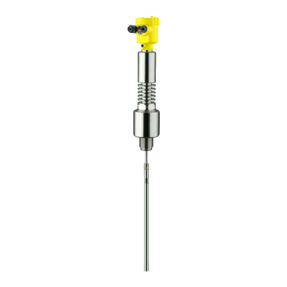
Tdr sensor for continuous level and interface measurement of liquids
Hide thumbs
Also See for VEGAFLEX 86:
- Operating instructions manual (104 pages) ,
- Quick setup manual (20 pages) ,
- Operating instruction (92 pages)

Subscribe to Our Youtube Channel
Related Manuals for Vega VEGAFLEX 86


Summary of Contents for Vega VEGAFLEX 86
-
Page 1: Operating Instructions
Operating Instructions TDR sensor for continuous level and interface measurement of liquids VEGAFLEX 86 Profibus PA Rod and cable probe -196 … +280 °C -196 … +450 °C Document ID: 44232... -
Page 2: Table Of Contents
Parameter adjustment with PACTware ................55 Set up with the quick setup ..................... 56 Saving the parameter adjustment data ................58 Set up with other systems DD adjustment programs ....................59 Diagnostics and servicing Maintenance ........................60 VEGAFLEX 86 • Profibus PA... - Page 3 Safety instructions for Ex areas Take note of the Ex specific safety instructions for Ex applications. These instructions are attached as documents to each instrument with Ex approval and are part of the operating instructions manual. Editing status: 2016-04-13 VEGAFLEX 86 • Profibus PA...
-
Page 4: About This Document
Action This arrow indicates a single action. Sequence of actions Numbers set in front indicate successive steps in a procedure. Battery disposal This symbol indicates special information about the disposal of bat- teries and accumulators. VEGAFLEX 86 • Profibus PA... -
Page 5: For Your Safety
During work on and with the device the required personal protective equipment must always be worn. Appropriate use VEGAFLEX 86 is a sensor for continuous level measurement. You can find detailed information about the area of application in chapter "Product description". -
Page 6: Namur Recommendations
The environment management system is certified according to DIN EN ISO 14001. Please help us fulfil this obligation by observing the environmental instructions in this manual: • Chapter "Packaging, transport and storage" • Chapter "Disposal" VEGAFLEX 86 • Profibus PA... -
Page 7: Product Description
Test certificate (PDF) - optional Go to www.vega.com "VEGA Tools" and "Instrument search". Enter the serial number. Alternatively, you can access the data via your smartphone: • Download the smartphone app "VEGA Tools" from the "Apple App Store" or the "Google Play Store" VEGAFLEX 86 • Profibus PA... -
Page 8: Principle Of Operation
– If necessary, further certificates Principle of operation Application area The VEGAFLEX 86 is a level sensor with cable or rod probe for continuous level or interface measurement, particularly suitable for applications in high temperatures up to +450 °C (842 °F). - Page 9 Upon reaching the product surface, a part of the microwave im- pulses is reflected. The other part passes through the upper product and is reflected by the interface. The running times to the two product layers are processed by the instrument. VEGAFLEX 86 • Profibus PA...
- Page 10 Example: upper medium dielectric constant 2, lower medium at least dielectric constant 12. Gas phase (L3) • Air or gas mixture • Gas phase - dependent on the application, gas phase does not always exist (d2 = 0) VEGAFLEX 86 • Profibus PA...
-
Page 11: Packaging, Transport And Storage
USB interface of a PC. For parameter adjustment of these instruments, the adjustment software PACTware with VEGA-DTM is required. You can find further information in the operating instructions "Interface adapter VEGACONNECT" (Document-ID 32628). VEGAFLEX 86 • Profibus PA... - Page 12 3 Product description The VEGADIS 81 is an external display and adjustment unit for VEGA VEGADIS 81 plics sensors. ® For sensors with double chamber housing the interface adapter "DISADAPT" is also required for VEGADIS 81. You can find further information in the operating instructions "VE- GADIS 81"...
- Page 13 You can find further information in the operating instructions manual "Bypass tube VEGAPASS 81". Centering If you mount the VEGAFLEX 86 in a bypass tube or standpipe, you have to avoid contact to the bypass tube by using a spacer at the probe end.
-
Page 14: Mounting
These are mainly: • Active measuring component • Process fitting • Process seal Process conditions are particularly: • Process pressure • Process temperature • Chemical properties of the medium • Abrasion and mechanical influences VEGAFLEX 86 • Profibus PA... -
Page 15: Mounting Instructions
Mounting instructions Installation position Mount VEGAFLEX 86 in such a way that the distance to vessel instal- lations or to the vessel wall is at least 300 mm (12 in). In non-metallic vessels, the distance to the vessel wall should be at least 500 mm (19.7 in). - Page 16 ≤ 150 mm ( 5.91") DN40 ... DN150 ≤ 100 mm (3 .94") > DN150 ... DN200 Fig. 6: Mounting socket When welding the socket, make sure that the socket is flush with the vessel top. VEGAFLEX 86 • Profibus PA...
- Page 17 Do not mount the instruments in or above the filling stream. Make sure that you detect the product surface, not the inflowing product. Fig. 8: Mounting of the sensor with inflowing medium The reference plane for the measuring range of the sensors is the Measuring range sealing surface of the thread or flange. VEGAFLEX 86 • Profibus PA...
- Page 18 If durability is no problem, we recommend the use of uncoated metal standpipes. When the VEGAFLEX 86 is used in bypass tubes, contact with the tube wall must be avoided. We recommend for this purpose a cable probe with centering weight.
- Page 19 For standpipes, select the probe length such that the upper blocking distance (dead band) of the probe is above the upper ventilation hole. This allows you to measure the total level range of the medium in the VEGAFLEX 86 • Profibus PA...
- Page 20 If durability is no problem, we recommend the use of uncoated metal standpipes. When the VEGAFLEX 86 is used in standpipes, contact with the tube wall must be avoided. We recommend for this purpose a cable probe with centering weight.
- Page 21 Instructions for the measurement: • The 100 % point with standpipes should be below the upper ventilation hole. • The 0 % point in standpipes should be above the gravity or center- ing weight. VEGAFLEX 86 • Profibus PA...
- Page 22 Any undefined change of this condition can lead to measurement errors. If there is a danger of the rod probe touching the vessel wall, then the probe must be fastened at the bottom end. VEGAFLEX 86 • Profibus PA...
- Page 23 L = L1 + 270 mm (10.63 in) ø < 8 mm (ø < 0.315") 550 mm (21.65") Fig. 13: Tensioning component for cable versions Holding screw M8 Holding screw M12 L1 Max. measuring length Probe length L = L1 + 270 mm (10.63 in) VEGAFLEX 86 • Profibus PA...
- Page 24 To compensate for the resulting changes in signal runtime, let the instrument determine the probe length automatically. You can find further information in the supplementary instructions of the rod and cable components. VEGAFLEX 86 • Profibus PA...
-
Page 25: Connecting To Power Supply
With plastic housing, the NPT cable gland or the Conduit steel tube must be screwed without grease into the threaded insert. Max. torque for all housings, see chapter "Technical data". VEGAFLEX 86 • Profibus PA... -
Page 26: Connecting
4. Remove approx. 10 cm (4 in) of the cable mantle, strip approx. 1 cm (0.4 in) of insulation from the ends of the individual wires 5. Insert the cable into the sensor through the cable entry Fig. 14: Connection steps 5 and 6 - Single chamber housing VEGAFLEX 86 • Profibus PA... -
Page 27: Wiring Plan, Single Chamber Housing
10. Reinsert the display and adjustment module, if one was installed 11. Screw the housing lid back on The electrical connection is finished. Wiring plan, single chamber housing The following illustration applies to the non-Ex, Ex-ia and Ex-d-ia version. VEGAFLEX 86 • Profibus PA... -
Page 28: Wiring Plan, Double Chamber Housing
Wiring plan, double chamber housing The following illustrations apply to the non-Ex as well as to the Ex-ia version. Electronics compartment 6 7 8 Fig. 17: Electronics compartment, double chamber housing Internal connection to the terminal compartment 2 Contact pins for the display and adjustment module or interface adapter Selection switch for bus address VEGAFLEX 86 • Profibus PA... - Page 29 Terminal compartment - Radio module PLICS- MOBILE Status SIM-Card Test Fig. 19: Terminal compartment, radio module PLICSMOBILE Voltage supply You can find detailed information on connection in the supplementary instructions "PLICSMOBILE GSM/GPRS radio module". VEGAFLEX 86 • Profibus PA...
-
Page 30: Double Chamber Housing With Disadapt
Fig. 21: View to the plug connector M12 x 1 Pin 1 Pin 2 Pin 3 Pin 4 Contact pin Colour connection ca- Terminal, electronics ble in the sensor module Pin 1 Brown Pin 2 White Pin 3 Blue Pin 4 Black VEGAFLEX 86 • Profibus PA... -
Page 31: Wiring Plan - Version Ip 66/Ip 68, 1 Bar
The address setting is carried out either via: • The address selection switch in the electronics compartment of the instrument (address setting via hardware) • The display and adjustment module (address setting via software) • PACTware/DTM (address setting via software) VEGAFLEX 86 • Profibus PA... -
Page 32: Switch-On Phase
The addressing procedure is described in the operating instructions manual "Display and adjustment module. Switch-on phase After VEGAFLEX 86 is connected to the bus system, the instrument carries out a self-test for approx. 30 seconds. The following steps are carried out: •... -
Page 33: Set Up With The Display And Adjustment Module
The display and adjustment module is powered by the sensor, an ad- ditional connection is not necessary. Fig. 25: Installing the display and adjustment module in the electronics compart- ment of the single chamber housing VEGAFLEX 86 • Profibus PA... -
Page 34: Adjustment System
If you intend to retrofit the instrument with a display and adjustment module for continuous measured value indication, a higher lid with an inspection glass is required. Adjustment system Fig. 27: Display and adjustment elements 1 LC display Adjustment keys • Key functions [OK] key: VEGAFLEX 86 • Profibus PA... - Page 35 Any values not confirmed with [OK] will not be saved. Switch-on phase After switching on, the VEGAFLEX 86 carries out a short self-test where the device software is checked. The output signal transmits a fault signal during the switch-on phase.
-
Page 36: Parameter Adjustment - Quick Setup
Display: Language setting, settings for the measured value indication as well as lighting Diagnosis: Information, for example on the instrument status, pointer, reliability, AI FB 1 simulation, echo curve Additional adjustments: Sensor address, PIN, date/time, reset, copy sensor data VEGAFLEX 86 • Profibus PA... - Page 37 Hardware addressing is effective if an address less than 126 is set with the address selection switches on the electronics module of VEGAFLEX 86. In such case, software addressing has no effect - only the set hardware address applies. Software addressing Software addressing is only effective if address 126 or higher is set on the instrument with the address selection switches.
- Page 38 Note: The selection of the application has a considerable influence on all other menu items. Keep in mind that as you continue with the param- eter adjustment, individual menu items are only optionally available. VEGAFLEX 86 • Profibus PA...
- Page 39 You can enter the dielectric constant of the upper medium directly or have the value determined by the instrument. To do this you have to enter the measured or known distance to the interface. VEGAFLEX 86 • Profibus PA...
- Page 40 The distance refers tot he sensor reference plane (seal surface of the process fitting). Setup - Max. adjustment - This menu item is only available if you have selected interface meas- Interface urement under the menu item "Application". VEGAFLEX 86 • Profibus PA...
- Page 41 We generally recommend carrying out a false signal suppression to achieve the best possible accuracy. This should be done with the lowest possible level so that all potential interfering reflections can be detected. VEGAFLEX 86 • Profibus PA...
- Page 42 By activating the appropriate curve, the volume per- centage of the vessel is displayed correctly. If the volume should not be displayed in percent but e.g. in l or kg, a scaling can be also set in the menu item "Display". VEGAFLEX 86 • Profibus PA...
- Page 43 D Vessel height +h Positive socket correction value -h Negative socket correction value Setup - AI FB1 Since the adjustment is very comprehensive, the menu points of Function Blocks 1 (FB1) were put together in a submenu. VEGAFLEX 86 • Profibus PA...
- Page 44 The default setting is a damping of 0 s. Lock/unlock setup - Ad- In the menu item "Lock/unlock adjustment", you can protect the sen- justment sor parameters against unauthorized or inadvertent modification. The PIN is activated/deactivated permanently. VEGAFLEX 86 • Profibus PA...
- Page 45 Display - Displayed value In this menu item, you define the indication of the measured value on the display. You can display two different measured values. In this menu item, you define measured value 2. VEGAFLEX 86 • Profibus PA...
- Page 46 Values > 90 % indicate reliable measurement. If you have selected interface measurement under the menu item "Setup - Application", the peak values of the interface measurement are displayed in addition to the peak values of the level measurement. VEGAFLEX 86 • Profibus PA...
- Page 47 In this menu item you can simulate measured values via the current output. This allows the signal path to be tested, e.g. through down- stream indicating instruments or the input card of the control system. VEGAFLEX 86 • Profibus PA...
- Page 48 With the adjustment software PACTware and the PC the high-reso- lution echo curve can be displayed and used later on to assess the quality of the measurement. In this menu item, the internal clock of the sensor is adjusted. Additional adjustments - Date/Time VEGAFLEX 86 • Profibus PA...
- Page 49 Medium, dielectric constant Water-based, > 10 Superimposed gas phase Dielectric constant, upper medium (TS) Tube inner diameter 200 mm Max. adjustment - Level 100 % Max. adjustment - Level Distance: 0.000 m(d) - note block- ing distances VEGAFLEX 86 • Profibus PA...
- Page 50 AI FB1 Fail Safe Mode (behaviour in case of mal- Last Valid Out Value (last valid function) measured value) AI FB1 Fail Safe Value 0.00 % AI FB1 Target Mode Auto Display Menu item Default value Modified value Language Order-specific VEGAFLEX 86 • Profibus PA...
- Page 51 Primary Value (lin. percent level) AI FB2 scaling PV Scale (min.) AI FB2 scaling PV Scale (max.) 100 % AI FB2 Lin. Type Linear AI FB2 Out Scale Unit AI FB2 Out Scale Decimal Point #.## VEGAFLEX 86 • Profibus PA...
- Page 52 • Read from sensor: Read data from sensor and save in the display and adjustment module • Write to sensor: Save data from the display and adjustment mod- ule back into the sensor VEGAFLEX 86 • Profibus PA...
- Page 53 Info - Instrument name In this menu, you read out the instrument name and the instrument serial number. Info - Instrument version In this menu item, the hardware and software version of the sensor is displayed. VEGAFLEX 86 • Profibus PA...
-
Page 54: Saving The Parameter Adjustment Data
If it is necessary to exchange a sensor, the display and adjustment module is inserted into the replacement instrument and the data are likewise written into the sensor via the menu item "Copy sensor data". VEGAFLEX 86 • Profibus PA... -
Page 55: Setup With Pactware
Further setup steps are described in the operating instructions manu- al "DTM Collection/PACTware" attached to each DTM Collection and which can also be downloaded from the Internet. Detailed descrip- tions are available in the online help of PACTware and the DTMs. VEGAFLEX 86 • Profibus PA... -
Page 56: Set Up With The Quick Setup
The standard version is available as a download under www.vega.com/downloads and "Software". The full version is avail- able on CD from the agency serving you. Set up with the quick setup... - Page 57 2 Extended adjustment Maintenance Quick setup With quick setup you can carry out the parameter adjustment of VEGAFLEX 86 for your application in just a few simple steps. The assistant-driven adjustment includes the basic settings for simple, reliable setup and commissioning. Information: If the function is inactive, then possibly no instrument is connected.
-
Page 58: Saving The Parameter Adjustment Data
7 Setup with PACTware Saving the parameter adjustment data We recommend documenting or saving the parameter adjustment data via PACTware. That way the data are available for multiple use or service purposes. VEGAFLEX 86 • Profibus PA... -
Page 59: Set Up With Other Systems
Set up with other systems DD adjustment programs Device descriptions as Enhanced Device Description (EDD) are available for DD adjustment programs such as, for example, AMS™ and PDM. The files can be downloaded at www.vega.com/downloads under "Software". VEGAFLEX 86 • Profibus PA... -
Page 60: Diagnostics And Servicing
Changes in the measure- ment conditions during operation or buildup on the sensor can thus be recognized. The echo curve of the setup is stored via: • PC with PACTware/DTM VEGAFLEX 86 • Profibus PA... -
Page 61: Status Messages
This status message is inactive by default. It can be activated by the user via PACTware/DTM or EDD. Maintenance: Due to external influences, the instrument function is limited. The measurement is affected, but the measured value is VEGAFLEX 86 • Profibus PA... - Page 62 – Cable probe broken or – Check probe and Bit 13 rod probe defective exchange, if neces- Probe loss sary F080 – General software error – Briefly separate oper- Bit 5 ating voltage General software error VEGAFLEX 86 • Profibus PA...
- Page 63 – Check operating Bit 14 voltage voltage Imper- – Check connection missible cables operating voltage F267 – Sensor cannot start – Exchanging the elec- tronics No execut- – Send instrument for able sensor repair software VEGAFLEX 86 • Profibus PA...
- Page 64 – If necessary, increase missible operating voltage operating voltage Maintenance The following table shows the error codes and text messages in the status message "Maintenance" and provides information on causes as well as corrective measures. VEGAFLEX 86 • Profibus PA...
-
Page 65: Rectify Faults
The operator of the system is responsible for taking suitable meas- tion occurs ures to rectify faults. Procedure for fault recti- The first measures are: fication • Evaluation of fault messages, for example via the display and adjustment module • Checking the output signal VEGAFLEX 86 • Profibus PA... - Page 66 – Amplitude or position of a – Determine the reason for the false signal has changed (e.g. changed false signals, carry out buildup); false signal suppres- false signal suppression, e.g. sion no longer matches with buildup VEGAFLEX 86 • Profibus PA...
- Page 67 • Constant level • Filling • Emptying The images in column "Error pattern" show the real level as a broken line and the level displayed by the sensor as a continuous line. VEGAFLEX 86 • Profibus PA...
- Page 68 – Amplitude or position of a false – Determine the reason for the signal has changed (e.g. con- changed false signals, carry out densation, buildup); false signal false signal suppression, e.g. suppression no longer matches with condensation actual conditions VEGAFLEX 86 • Profibus PA...
- Page 69 – In case of interferences due to installations in the close range: Change polarisation direction – After eliminating the false sig- nals, the false signal suppres- sion must be deleted. Carry out a new false signal suppression VEGAFLEX 86 • Profibus PA...
-
Page 70: Exchanging The Electronics Module
24 hour service hotline Should these measures not be successful, please call in urgent cases the VEGA service hotline under the phone no. +49 1805 858550. The hotline is also available outside normal working hours, seven days a week around the clock. -
Page 71: Exchange Or Shorten Cable/Rod
4. Screw the new rod and the new cable manually to the thread on the process fitting. 5. Exert counterforce with the second fork spanner and tighten the measuring rod or cable on the flat surfaces with a torque of 20 Nm (15 lbf ft). Fig. 51: Exchange cable or rod VEGAFLEX 86 • Profibus PA... - Page 72 8. Enter new probe length and then carry out a fresh adjustment (see "Setup procedure, Carrying out min. adjustment - Carrying out max. adjustment"). Fig. 52: Shortening the cable probe A Gravity weight - cable ø 4 mm B Gravity weight - cable ø 2 mm C Centering weight - cable ø 2 mm 1 Threaded pins 2 Thread M8 for eye-bolt Fixing screw - centering weight VEGAFLEX 86 • Profibus PA...
-
Page 73: Software Update
Attach the completed form and, if need be, also a safety data sheet outside on the packaging • Please contact the agency serving you to get the address for the return shipment. You can find the agency on our home page www.vega.com. VEGAFLEX 86 • Profibus PA... -
Page 74: Dismount
Pass the instrument directly on to a spe- cialised recycling company and do not use the municipal collecting points. These may be used only for privately used products according to the WEEE directive. VEGAFLEX 86 • Profibus PA... -
Page 75: Supplement
Ʋ Supporting material 316L Ʋ Glass potting Borosilicate glass GPC 540 VEGAFLEX 86 • Profibus PA... - Page 76 Ʋ -196 … +450 °C (-321 … +842 °F) max. 400 Nm (295 lbf ft) Torque for exchangeable cable or rod probe (in the process fitting) Ʋ Cable: ø 2 mm (0.079 in) 20 Nm (14.75 lbf ft) VEGAFLEX 86 • Profibus PA...
- Page 77 Ʋ Medium Water/Oil (dielectric constant ~2.0) Ʋ Installation Probe end does not touch the vessel bottom Sensor parameter adjustment No gating out of false signals carried out With interface measurement = 2.0 VEGAFLEX 86 • Profibus PA...
- Page 78 Depending on the installation conditions, deviations can occur which can be rectified by adapting the adjust- ment or changing the measured value offset in the DTM service mode The dead bands can be optimized via a false signal suppression. VEGAFLEX 86 • Profibus PA...
- Page 79 25 mm (0.984") 2 mm (0.079") -2 mm (0.079") -25 mm (-0.984") 0,15 m 0,2 m 0,05 m (5.906") (7.874") (1.968") 0,05 m (1.968") Fig. 55: Deviation VEGAFLEX 86 in rod version in oil Dead band - no measurement possible in this area Probe length VEGAFLEX 86 • Profibus PA...
- Page 80 -2 mm (-0.079 ") -15 mm (-0.591 " 0,15 m 0,2 m 0,1 m (5.906 (7.874 " ") (3.937 0,08 m ") (3.15 ") Fig. 57: Deviation VEGAFLEX 86 in cable version 2 mm (0.079 in), in oil Dead band - no measurement possible in this area Probe length VEGAFLEX 86 • Profibus PA...
- Page 81 0.10 % 0.61 % 1.2 % 2.5 % 4.9 % 200 °C/392 °F 0.05 % 0.37 % 0.76 % 1.6 % 3.1 % 400 °C/752 °F 0.03 % 0.25 % 0.53 % 1.1 % 2.2 % VEGAFLEX 86 • Profibus PA...
- Page 82 Time span after a sudden measuring distance change by max. 0.5 m in liquid applications, max 2 m with bulk solids applications, until the output signal has taken for the first time 90 % of the final value (IEC 61298-2). VEGAFLEX 86 • Profibus PA...
- Page 83 392°F 572°F 572°F 842°F -20°C / -4°F -40°C / -40°F Fig. 60: Ambient temperature - process temperature, standard version Ambient temperature Process temperature (depending on the seal material) Aluminium housing Plastic housing Stainless steel housing, precision casting Stainless steel housing, electropolished VEGAFLEX 86 • Profibus PA...
- Page 84 4 g at 5 … 200 Hz according to EN 60068-2-6 (vibration with resonance) Ʋ Rod probe 1 g with 5 … 200 Hz according EN 60068-2-6 (vibration at resonance) with rod length 50 cm (19.69 in) VEGAFLEX 86 • Profibus PA...
- Page 85 25 mm (0.984 in) with 25 °C (77 °F) Ʋ Diameter approx. 8 mm (0.315 in) Ʋ Colour - Non-Ex version Black Ʋ Colour - Ex-version Blue Display and adjustment module Display element Display with backlight VEGAFLEX 86 • Profibus PA...
- Page 86 13.5 … 17.5 V DC FISCO model Ʋ Ex-ia instrument - Power supply 13.5 … 24 V DC ENTITY model Ʋ Ex-d-ia instrument No lighting (integrated ia barrier) Number of sensors per DP/PA segment coupler, max. Ʋ Non-Ex VEGAFLEX 86 • Profibus PA...
-
Page 87: Communication Profibus Pa
Instruments with approvals can have different technical specifications depending on the version. For that reason the associated approval documents of these instruments have to be carefully noted. They are part of the delivery or can be downloaded under www.vega.com, "VEGA Tools" and "Instrument search" as well as in the download area. - Page 88 The below block diagram below shows which data can be accessed by the PLC. Fig. 63: VEGAFLEX 86: Block diagram with AI FB 1 … AI FB 3 OUT values TB Transducer Block FB 1 … FB 3 Function Block Module of the PA sensors For the cyclic data traffic, VEGAFLEX 86 provides the following modules: • AI FB1 (OUT) – Out value of the AI FB1 after scaling • AI FB2 (OUT) –...
- Page 89 Fig. 64: Data format of the output signal The status byte corresponds to profile 3.02 "Profibus PA Profile for Process Control Devices" coded. The status "Measured value OK" is coded as 80 (hex) (Bit7 = 1, Bit6 … 0 = 0). VEGAFLEX 86 • Profibus PA...
- Page 90 0 x 80 good (non-cascade) - OK 0 x 84 good (non-cascade) - ac- Static revision (FB, TB) changed (10 sec. active, after tive block alarm the parameter of the static category has been written) VEGAFLEX 86 • Profibus PA...
-
Page 91: Dimensions
Hi-Hi-Alarm tive critical alarm - high limited 11.3 Dimensions The following dimensional drawings represent only an extract of all possible versions. Detailed dimensional drawings can be downloaded at www.vega.com/downloads under "Drawings". Plastic housing ~ 69 mm ~ 84 mm (2.72") (3.31") - Page 92 Aluminium housing with protection rating IP 66/IP 68 (1 bar) ~ 105 mm ~ 150 mm (4.13") (5.91") ø 86 mm ø 86 mm (3.39") (3.39") M16x1,5 M20x1,5 M20x1,5 M20x1,5/ ½ NPT Fig. 68: Housing version with protection rating IP 66/IP 68 (1 bar) - with integrated display and adjustment module the housing is 9 mm/0.35 in higher Single chamber version Double chamber version VEGAFLEX 86 • Profibus PA...
- Page 93 ø 86 mm ø 80 mm ø 79 mm (3.39") (3.15") (3.11") M16x1,5 M20x1,5 M20x1,5/ ½ NPT M20x1,5/ ½ NPT Fig. 70: Housing version with protection rating IP 66/IP 68 (1 bar) - with integrated display and adjustment module the housing is 9 mm/0.35 in higher Single chamber version, electropolished Single chamber version, precision casting Double chamber version, precision casting VEGAFLEX 86 • Profibus PA...
- Page 94 11 Supplement VEGAFLEX 86, cable version with gravity weight SW 60 (2.36") G1½ / 1½ NPT ø 4 mm ø 4 mm (0.16") (0.16") ø 2 mm (0.08") ø 20 mm ø 20 mm (0.79") (0.79") ø 16 mm ø 16 mm ø...
- Page 95 11 Supplement VEGAFLEX 86, cable version with centering weight SW 60 (2.36") G1½ / 1½ NPT ø 2 mm / ø 4 mm ø 2 mm / ø 4 mm (0.16") (0.08") (0.08") (0.16") Fig. 72: VEGAFLEX 86, threaded version with centering weight Sensor length, see chapter "Technical data" ø 40 mm (1.57 in) ø 45 mm (1.77 in) ø 75 mm (2.95 in) ø 95 mm (3.74 in) Cable ø 2 mm (0.079 in)/cable ø 4 mm (0.157 in), temperature version -196 … +280 °C (-321 … 536 °F) -...
- Page 96 11 Supplement VEGAFLEX 86, rod version SW 60 (2.36") G1½ / 1½ NPT ø 16mm ø 16 mm (0.63") (0.63") Fig. 73: VEGAFLEX 86, threaded version Sensor length, see chapter "Technical data" Rod ø 16 mm (0.63 in), temperature version -196 … +280 °C (-321 … 536 °F) Rod ø 16 mm (0.63 in), temperature version -196 … +450 °C (-321 … 842 °F) Max. height of the vessel insulation VEGAFLEX 86 • Profibus PA...
-
Page 97: Industrial Property Rights
Les lignes de produits VEGA sont globalement protégées par des droits de propriété intellec- tuelle. Pour plus d'informations, on pourra se référer au site www.vega.com. VEGA lineas de productos están protegidas por los derechos en el campo de la propiedad indus- trial. Para mayor información revise la pagina web www.vega.com. - Page 98 – Electronics module 12 Gas phase 39 – Fixing facility 13 GSD file 87 – Rod components 13 – Spacer 13 Reset 49 Hardware addressing 32, 37 Scaling 44 Inflowing medium 17 Scaling unit 44 VEGAFLEX 86 • Profibus PA...
- Page 99 Sensor status 46 Service hotline 70 Simulation 47 Software addressing 32, 37 Special parameters 53 Status bytes PA output value 90 Telegram configuration 89 Type label 7 Type of medium 38 Units 38 Vessel insulation 22 VEGAFLEX 86 • Profibus PA...
- Page 100 Subject to change without prior notice © VEGA Grieshaber KG, Schiltach/Germany 2016 VEGA Grieshaber KG Phone +49 7836 50-0 Am Hohenstein 113...
Need help?
Do you have a question about the VEGAFLEX 86 and is the answer not in the manual?
Questions and answers